Válvula de Bleed Milton Roy
•
1 j'aime•191 vues

Válvula de Bleed Milton Roy SAIBA MAIS Site: www.vibropac.com.br Tel: +55 11 2108-5600 E-mail: vibropac@vibropac.com.br

Recommandé
Contenu connexe
Tendances
Tendances (17)
Similaire à Válvula de Bleed Milton Roy
Similaire à Válvula de Bleed Milton Roy (20)
Plus de Vibropac
Plus de Vibropac (20)
Dernier
Dernier (20)
Válvula de Bleed Milton Roy
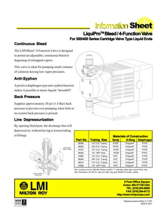
- 1. Materials of ConstructionMaterials of ConstructionMaterials of ConstructionMaterials of ConstructionMaterials of Construction Part No.Part No.Part No.Part No.Part No. Tubing SizeTubing SizeTubing SizeTubing SizeTubing Size Body O-Ring DiaphragmBody O-Ring DiaphragmBody O-Ring DiaphragmBody O-Ring DiaphragmBody O-Ring Diaphragm 36389 1/4" O.D. Tubing PVDF Polyprel® PTFE 36390 3/8" O.D. Tubing PVDF Polyprel® PTFE 37075 1/2" O.D. Tubing PVDF Polyprel® PTFE 36393 1/4" NPT Pipe PVDF Polyprel® PTFE 37995 1/4" O.D. Tubing PVC Polyprel® PTFE 38004 3/8" O.D. Tubing PVC Polyprel® PTFE 38015 1/2" O.D. Tubing PVC Polyprel® PTFE 37984 1/4" NPT Pipe PVC Polyprel® PTFE InformationInformationSheet LiquiProLiquiProLiquiProLiquiProLiquiProTMTMTMTMTM Bleed/4-FunctionVBleed/4-FunctionVBleed/4-FunctionVBleed/4-FunctionVBleed/4-FunctionValvealvealvealvealve For 300/400 Series Cartridge VFor 300/400 Series Cartridge VFor 300/400 Series Cartridge VFor 300/400 Series Cartridge VFor 300/400 Series Cartridge Valve Talve Talve Talve Talve Type Liquid Endsype Liquid Endsype Liquid Endsype Liquid Endsype Liquid Ends Replaces same of Rev.C 11/97 1825.D 6/01 Continuous BleedContinuous BleedContinuous BleedContinuous BleedContinuous Bleed The LMI Bleed / 4-Function Valve is designed to permit an adjustable, continuous bleed or degassing of entrapped vapors. This valve is ideal for pumping small volumes of solutions having low vapor pressures. 8 Post Office Square8 Post Office Square8 Post Office Square8 Post Office Square8 Post Office Square Acton, MA 01720 USAActon, MA 01720 USAActon, MA 01720 USAActon, MA 01720 USAActon, MA 01720 USA TEL:(978)263-9800TEL:(978)263-9800TEL:(978)263-9800TEL:(978)263-9800TEL:(978)263-9800 FAX:(978)264-9172FAX:(978)264-9172FAX:(978)264-9172FAX:(978)264-9172FAX:(978)264-9172 http://www.Imipumps.comhttp://www.Imipumps.comhttp://www.Imipumps.comhttp://www.Imipumps.comhttp://www.Imipumps.com Anti-SyphonAnti-SyphonAnti-SyphonAnti-SyphonAnti-Syphon Apositivediaphragm-typeanti-syphonfunction makes it possible to meter liquids "downhill". Back PressureBack PressureBack PressureBack PressureBack Pressure Supplies approximately 20 psi (1.4 Bar) back pressure to prevent over-pumping when little or no system back pressure is present. Line DepressurizationLine DepressurizationLine DepressurizationLine DepressurizationLine Depressurization Part numbers are for 300/400 Series LiquiPro TM cartridge valve type Liquid Ends only. See Publication #1746 for ball and seal ring type Bleed/4-Function valves. By opening bleed port, the discharge line will depressurize, without having to loosen tubing orfittings.
- 2. InstructionInstructionInstructionInstructionInstruction SheetSheetSheetSheetSheet LiquiPro™ Bleed / 4-Function Valve For 300/400 Series Cartridge Valve Type Liquid Ends A. PRIMING 1. Connect bleed return tubing to bleed (relief) port. 2. Route tubing to solution tank. Be sure the end of tubing is above the maximum solution level. Do notDo notDo notDo notDo not submerge tubisubmerge tubisubmerge tubisubmerge tubisubmerge tubing in solution.ng in solution.ng in solution.ng in solution.ng in solution. 3. Set pump at 80% speed and 100% stroke. Start pump. Withscrewdriverrotatebleedadjustmentscrewcoun- terclockwise two (2) full turns. When solution begins to flow through translucent bleed return tub- ing, the pump is primed. 4. Stop pump. NOTE: (a) Pump is normally self-priming if suction lift is no more than 5 ft (1.5 m), valves in the pump are wet with water (pump is shipped from factory with water in pump head) and the above steps (A1 through A3A1 through A3A1 through A3A1 through A3A1 through A3) are followed. (b) If the pump does not self prime, remove Bleed/ 4 Function Valve and Discharge Cartridge Valve, and pour water or solution slowly into discharge port until it is filled. Replace Cartridge Valve, and follow steps (A1 through A3)(A1 through A3)(A1 through A3)(A1 through A3)(A1 through A3) thereafter. B. BLEED ADJUSTMENT 1. Start pump and let pump inject solution into the discharge line. 2. Close the bleed adjustment screw by rotating it clock- wise with a screwdriver. 3. Now adjust the pump stroke length and/or speed (fre- quency) to a range approximately 25% higher than you would normally want for the process. 4. Slowly rotate bleed adjustment screw counter-clockwise until just a small amount of solution begins to trickle down inside the bleed return tubing. A small amount of solution pumped back to the tank with each stroke of the pump will allow gas and air to escape without air or gas locking in the pump head. C. DEPRESSURIZING DISCHARGE LINE 1. It is possible to depressurize discharge line and pump head without removal of tubing or loosening of fittings. Be sure injection check valve is properly installed and is operating. If a gate valve or globe has been installed down- stream of injection check valve, it should be closed. Be certain bleed return tubing is connected and run to solution supply tank. 2. With a screwdriver, rotate bleed adjustment screw counter-clockwise two (2) full turns. A small amount of solution in discharge line should drain back to the supply tank. 3. The discharge line is now depressurized. 4. If injection check valve is of higher elevation than pump head, disconnecting tubing at injection check valve end will allow air to enter and cause solution to drain back to tank. METHOD OF OPERATION
- 3. yeK .oN .oNtraP noitpircseD 59973 40083 48973 98363 09363 39363 51083 57073 1 20083 CVP"4/1,ydoBVF4/B 1 11083 CVP"8/3,ydoBVF4/B 1 98973 CVPTPN"4/1,ydoBVF4/B 1 50743 FDVP"4/1,ydoBVF4/B 1 70743 FDVP"8/3,ydoBVF4/B 1 56853 FDVPTPN"4/1,ydoBVF4/B 1 61083 CVP"2/1,ydoBVF4/B 1 90743 FDVP"2/1,ydoBVF4/B 1 2 08263 msApaCS/A 1 1 1 1 1 1 1 1 3 82652 tuN 4 4 4 4 4 4 4 4 4 72652 wercS 4 4 4 4 4 4 4 4 5 13652 tuNgnilpuoC 1 1 1 1 1 1 1 1 6 01-63652 gnibuT 1 1 1 1 1 1 1 1 7 99201 tuNgnilpuoC 1 1 1 1 11401 tuNgnilpuoC 1 1 8 36682 elurreF 1 1 9 63162 gnibuTDO"8/3,gniRpmalC 1 1 30273 gnibuTDO"2/1,gniRpmalC 1 1 01 17123 feileR,paC 1 1 1 1 1 1 1 1 11 67843 deelB,wercS 1 1 1 1 1 1 1 1 21 86843 csiD 1 1 1 1 1 1 1 1 31 37123 mgarhpaiD 1 1 1 1 1 1 1 1 41 57123 ®lerpyloPllamS,gniR-O 1 1 1 1 1 1 1 1 51 67123 ®lerpyloPegraL,gniR-O 1 1 1 1 1 1 1 1 61 70163 rehsaW 1 1 1 1 1 1 1 1
- 4. © 2001 LMI Milton Roy - All Rights Reserved Printed in USA Specifications subject to change without notice. 8 Post Office Square8 Post Office Square8 Post Office Square8 Post Office Square8 Post Office Square Acton, MA 01720 USAActon, MA 01720 USAActon, MA 01720 USAActon, MA 01720 USAActon, MA 01720 USA TEL:(978)263-9800TEL:(978)263-9800TEL:(978)263-9800TEL:(978)263-9800TEL:(978)263-9800 FAX:(978)264-9172FAX:(978)264-9172FAX:(978)264-9172FAX:(978)264-9172FAX:(978)264-9172 http://www.Imipumps.comhttp://www.Imipumps.comhttp://www.Imipumps.comhttp://www.Imipumps.comhttp://www.Imipumps.com LiquiPro is a trademark of Liquid Metronics Incorporated Polyprel is a registered trademark of Liquid Metronics Incorporated