SlideShare une entreprise Scribd logo
1  sur  6
Télécharger pour lire hors ligne
1
Abstract— A cycloconverter is a type of power controller in which
an alternating voltage at supply frequency is converted to an
alternating voltage at load frequency without any intermediate
D.C. This paper describes the working principle and operation of
single phase to single phase cycloconverter and some applications.
Keywords— Static frequency changers (SFCs); Intergroup
reactor (IGR)
I. INTRODUCTION
Cycloconverters are static frequency changers (SFCs)
designed to produce adjustable voltage adjustable frequency
AC power from a constant voltage constant frequency AC
source without any intermediate DC link. The basics of these
converters were proposed by Hazeltine in 1926, and the first
cycloconverter was built in 1930s using mercury arc valves
for converting standard 50Hz supply to single-phase Hz
supply for use in ac traction system in Germany. However,
the practical and commercial utilization of these schemes
waited until the SCRs became available in the 1960s. With
the development of large power SCRs and microprocessor-
based control, the cycloconverter today is a matured practical
converter for application in large-power low-speed variable-
voltage variable-frequency (VVVF) ac drives in cement and
steel rolling mills as well as in variable-speed constant-
frequency (VSCF) systems in aircraft and naval ships.
Basically, cycloconverters are of two types:
i) Step-down cycloconverters: The output frequency fo
is lower than the supply frequency fs.
ii) Step-up cycloconverters: The output frequency fo is
more than the supply frequency fs.
Figure 1. Symbol of cycloconverter
II. PRINCIPLE OF OPERATION
The basic principle of operation of a cycloconverter is
explained with reference to an equivalent circuit shown in
Fig. 2. Each two-quadrant converter (phase-controlled) is
represented as an alternating voltage source, which
corresponds to the fundamental voltage component obtained
at its output terminals. The diodes connected in series with
each voltage source, show the unidirectional conduction of
each converter, whose output voltage can be either positive or
negative, being a two-quadrant one, but the direction of
current is in the direction as shown in the circuit, as only
thyristors − unidirectional switching devices, are used in the
two converters. Normally, the ripple content in the output
voltage is neglected.
The control principle used in an ideal cyclo-converter is to
continuously modulate the firing angles of the individual
converters, so that each produces the same sinusoidal (ac)
voltage at its output terminals. Thus, the voltages of the two
generators (Fig. 2)have the same amplitude, frequency and
phase, and the voltage of the cycloconverter is equal to the
voltage of either of these generators. It is possible for the
mean power to flow either ‘to’ or ‘from’ the output terminals,
and the cycloconverter is inherently capable of operation with
loads of any phase angle − inductive or capacitive. Because
of the uni-directional current carrying property of the
individual converters, it is inherent that the positive half cycle
of load current must always be carried by the positive
converter, and the negative half-cycle by the negative
converter, regardless of the phase of the current with respect
to the voltage. This means that each two quadrant converter
operates both in its rectifying (converting) and in its inverting
region during the period of its associated half-cycle of
current.
Figure 2. Equivalent circuit of cycloconverter
Cycloconverters
Vishal N. Popat
Electronics & Communication Dept
Institute Of Technology
Nirma University
Ahmedabad, India
12bec072@nirmauni.ac.in
2
Figure 3. Basic waveforms showing working of cycloconverter
The output voltage and current waveforms, illustrating the
operation of an ideal cycloconverter circuit with loads of
various displacement angles, are shown in Fig. 3. The
displacement angle of the load (current) is 0° (Fig. 3a). In this
case, each converter carries the load current only, when it
operates in its rectifying region, and it remains idle
throughout the whole period in which its terminal voltage is
in the inverting region of operation. In Fig. 3b, the
displacement angle of the load is 60° lagging. During the first
120° period of each half cycle of load current, the associated
converter operates in its rectifying region, and delivers power
to the load. During the latter 60° period in the half cycle, the
associated converter operates in its inverting region, and
under this condition, the load is regenerating power back into
the cycloconverter output terminals, and hence, into the ac
system at the input side.
III. SINGLE-PHASE TO SINGLE-PHASE CIRCUIT-STEP-UP
CONVERTER
A) Mid-point cycloconverters
Figure 4. Mid-point type cycloconverter circuit
It consists of a single phase transformer with mid tap on the
secondary windings and four thyristors. Two of these
thyristors P1 and P2 are for positive group and the other two
N1 and N2 are for the negative group. Load is connected
between secondary winding mid-point 0 and terminal A as
shown in fig. 4.
The load which is assumed to be an R Load is connected as
shown. In fig. 5, during the positive half cycle both SCRs P1
and N2 are forward biased from wt=0 to wt=π. As such P1 is
turned on at wt=0 so that load voltage is positive with
terminal A positive and 0 negative. The load voltage now
follows the positive envelope of the supply voltage, fig. 5. At
instant wt1 P1 is force commutated and forward-biased
thyristors N2 is turned on so that load voltage is negative
with terminal 0 positive and A negative. The load or output
voltage now traces the negative envelope of the supply
voltage. At wt2, N2 is force commutated and P1 is turned on,
the load voltage is now positive and follows the positive
envelope by supply voltage. The cycle continues till wt=π.
After wt=π, terminal b is positive with respect to terminal a;
both SCRs P2 and N1 are therefore forward biased from
wt=π to 2π. At wt=π, N2 is force commutated and forward
biased SCR P2 is turned on. In this manner, thyristors P1 and
N2 for first half cycle and P2 and N1 for the other half cycle
and so on are switched alternately between positive and
negative envelopes at a high frequency. We observe that
fo=6fs and hence a step up Cycloconverter.
3
Figure 5. Waveform for step-up cycloconverter
IV. BRIDGE - TYPE CYCLOCONVERTERS
Figure 6. Bridge type cycloconverter
This Cycloconverter consists of eight thyristors, P1 to P4 for
positive group and the remaining four for the negative group.
During the positive half cycle of the supply voltage, thyristors
pairs P1, P4 and N1, N4 are forward biased from wt=0 to
wt=π. At wt=0, P1 and P4 are turned on together so that the
load voltage is positive with terminal A positive with respect
to O. and thus load voltage traverses the positive envelope of
supply voltage. At wt1 P1 and P4 are force commutated and
the pair N1 and N4 is turned on. And thus the cycle repeats.
At wt=π, thyristors pairs P2, P3 and N2, N3 are forward
biased and thus the cycle repeats for wt=2π. In this manner, a
high frequency turning-on and force commutation of pairs
P1P4, N1N4 and pairs P2P3, N2N3 gives a carrier frequency
modulated output voltage across load terminals.
V. SINGLE-PHASE TO SINGLE-PHASE CIRCUIT-STEP-
DOWN CONVERTER
A single-phase to single-phase Cycloconverter is shown in
fig. 6.Two full-wave fully controlled bridge converter
circuits, using four thyristors for each bridge, are connected
in opposite direction (back to back), with both bridges being
fed from ac supply (50 Hz). Bridge 1 (P – positive) supplies
load current in the positive half of the output cycle, while
bridge 2 (N – negative) supplies load current in the negative
half. The two bridges should not conduct together as this will
produce short-circuit at the input. In this case, two thyristors
come in series with each voltage source. When the load
current is positive, the firing pulses to the thyristors of bridge
2 are inhibited, while the thyristors of bridge 1 are triggered
by giving pulses at their gates at that time. Similarly, when
the load current is negative, the thyristors of bridge 2 are
triggered by giving pulses at their gates, while the firing
pulses to the thyristors of bridge 1 are inhibited at that time.
This is the circulating-current free mode of operation. Thus,
the firing angle control scheme must be such that only one
converter conduct at a time, and the changeover of firing
pulses from one converter to the other, should be periodic
according to the output frequency. However, the firing angles
the thyristors in both converters should be the same to
produce a symmetrical output.
When a cycloconverter operates in the non-circulating current
mode, the control scheme is complicated, if the load current
is discontinuous. The control is somewhat simplified, if some
amount of circulating current is allowed to flow between
them. In this case, a circulating current limiting reactor is
connected between the positive and negative converters, as is
the case with dual converter, i.e. two fully controlled bridge
converters connected back to back, in circulating current
mode. The readers are requested to refer to any standard text
book. This circulating current by itself keeps both converters
in virtually continuous conduction over the whole control
range. This type of operation is termed as the circulating-
current mode of operation. The operation of the cyclo-
converter circuit with both purely resistive (R), and inductive
(R-L) loads is explained
For resistive load, the load current (instantaneous) goes to
zero, as the input voltage at the end of each half cycle (both
positive and negative) reaches zero. Thus, the conducting
thyristor pair in one of the bridges turns off at that time, i.e.
the thyristors undergo natural commutation. So, operation
with discontinuous current takes place, as current flows in the
load, only when the next thyristor pair in that bridge is
triggered, or pulses are fed at respective gates. Taking first
bridge 1 (positive), and assuming the top point of the ac
supply as positive with the bottom point as negative in the
positive half cycle of ac input, the odd-numbered thyristor
pair, P1 & P3 is triggered after phase delay (α1), such that
current starts flowing through the load in this half cycle. In
the next (negative) half cycle, the other thyristor pair (even-
numbered), P2 & P4 in that bridge conducts, by triggering
them after suitable phase delay from the start of zero-
crossing. The current flows through the load in the same
direction, with the output voltage also remaining positive.
This process continues for one more half cycle (making a
total of three) of input voltage (f2=f1/3= Hz).
Figure 7. Input (a) and output (b) voltage waveforms of a cycloconverter
with an output frequency of Hz for resistive(R) load
4
To obtain negative output voltage, in the next three half
cycles of input voltage, bridge 2 is used. Following same
logic, if the bottom point of the ac supply is taken as positive
with the top point as negative in the negative half of ac input,
the odd-numbered thyristor pair, N1 & N3 conducts, by
triggering them after suitable phase delay from the zero-
crossing. Similarly, the even-numbered thyristor pair, N2 &
N4 conducts in the next half cycle. Both the output voltage
and current are now negative. As in the previous case, the
above process also continues for three consecutive half cycles
of input voltage. From three waveforms, one combined
negative half cycle of output voltage is produced, having
same frequency as given earlier. The pattern of firing angle −
first decreasing and the increasing, is also followed in the
negative half cycle. One positive half cycle, along with one
negative half cycle, constitute one complete cycle of output
(load) voltage waveform, its frequency being Hz as stated
earlier. The ripple frequency of the output voltage/ current for
single–phase full-wave converter is 100 Hz, i.e., double of
the input frequency. It may be noted that the load (output)
current is discontinuous, as also load (output) voltage.
For R-L load, the load current may be continuous or
discontinuous depending on the firing angle and load power
factor. The load voltage and current waveforms are
shown for continuous and discontinuous load current in Fig. 8
and 9 respectively.
Figure 8. Input (a) and output (b) voltage, and current (c) waveforms for a
cycloconverter with discontinuous current
In this case, the output frequency is ¼ times to that of the
input frequency. So, four positive half cycles, or two full
cycles of the input to the full-wave bridge converter, are
required to produce one positive half cycle of the output
waveform. Here the current flows even after the input voltage
has reversed (after θ=π), till it reaches zero at (θ=β1) with
(π+α2) > β1 > π, due to inductance being present in series with
resistance, its value being low.
Figure 9. Input (a) and output (b) voltage, and current (c, d) waveforms
for a cyclo-converter with continuous load current.
VI. MODE OF OPERATION
A) Blocked Mode of Operation
The operation of the Cycloconverters is explained above in
ideal terms. When the load current is positive, the positive
converter supplies the required voltage and the negative
converter is disabled. On the other hand, when the load
current is negative, then the negative converter supplies the
required voltage and the positive converter is blocked. This
operation is called the blocked mode operation, and the
Cycloconverters using this approach are called blocking
mode Cycloconverters.
B) Circulating Current Mode of Operation
However, if by any chance both of the converters are enabled,
then the supply is short-circuited. To avoid this short circuit,
an intergroup reactor (IGR) can be connected between the
converters. Instead of blocking the converters during current
reversal, if they are both enabled, then a circulating current is
produced. This current is called the circulating current. It is
unidirectional because the thyristors allow the current to flow
in only one direction. Some Cycloconverters allow this
circulating current at all times. These are called circulating
current Cycloconverters.
5
Figure 10. Circulating current and IGR
VII. ADVANTAGES AND DISADVANTAGES OF
CYCLOCONVERTORS
A) ADVANTAGES
(1) In a cycloconverter, ac power at one frequency is
converted directly to a lower frequency in a single conversion
stage.
(2) Cycloconverter functions by means of phase
commutation, without auxiliary forced commutation circuits.
The power circuit is more compact, eliminating circuit losses
associated with forced commutation.
(3) Cycloconverter is inherently capable of power transfer in
either direction between source and load. It can supply power
to loads at any power factor, and is also capable of
regeneration over the complete speed range, down to
standstill. This feature makes it preferable for large reversing
drives requiring rapid acceleration and deceleration, thus
suited for metal rolling application.
(4) Commutation failure causes a short circuit of ac supply.
But, if an individual fuse blows off, a complete shutdown is
not necessary, and cycloconverter continues to function with
somewhat distorted waveforms. A balanced load is presented
to the ac supply with unbalanced output conditions.
(5) Cycloconverter delivers a high quality sinusoidal
waveform at low output frequencies, since it is fabricated
from a large number of segments of the supply waveform.
This is often preferable for very low speed applications.
(6) Cycloconverter is extremely attractive for large power,
low speed drives.
B) DISADVANTAGES
(1) Large number of thyristors is required in a cyclo-
converter, and its control circuitry becomes more complex. It
is not justified to use it for small installations, but is
economical for units above 20 kVA.
(2)For reasonable power output and efficiency, the output
frequency is limited to one-third of the input frequency.
(3) The power factor is low particularly at reduced output
voltages, as phase control is used with high firing delay
angle.
VIII. APPLICATIONS
The most interesting applications for cycloconverters
are as follows :
A) Variable Frequency Speed Control for AC
Machines
A normally input voltage with fixed frequency and amplitude is
converted through a cycloconverter to an output voltage with
continuously variable frequency and amplitude that is applied to
the ac machine for the purpose of controlling its speed. The 3
phase cycloconverters are mainly used in ac machine drive
systems running 3-phase synchronous motors, induction motors
and linear motors Cycloconverters are more advantageous when
used with a synchronous machine due to their output power
factor characteristics. A cycloconverter can supply lagging,
leading, or unity power factor loads while its input is always
lagging. A synchronous machine can draw any power factor
current from the cycloconverter. This characteristic operation
matches the cycloconverter to the synchronous machine. On the
other hand, induction machines can only draw lagging current.
However, cycloconverters are used in Scherbius drives for speed
control purposes driving wound rotor induction motors. The
static Scherbius drives are used in very high horsepower pump
and blower type applications. When cycloconverters are used to
run an ac machine, the leakage inductance of the machine filters
most of the higher frequency harmonics and reduces the
magnitudes of the lower order harmonics
B) Constant Frequency Power Supplies
The function of the cycloconverter is to provide a closely
regulated fixed frequency power output, from a variable
frequency power source connected to its input. A typical
variable speed constant frequency generating system is today
based on the slip-ring ac machine. The stator of the generator
is connected to a network with fixed frequency. The wound
rotor is fed from a 3-phase to 3-phase cycloconverter via the
slip rings.
C) Controllable Reactive Power Supply for
an AC System
Today there is a growing demand for controllable reactive
energy sources for industrial and power systems use. The
cycloconverter provides controllable reactive power for the ac
system to which it is connected. This will compensate the
reactive power of the loads connected to the system.
D) AC System Interties
The cycloconverter is used to tie together two independent ac
power systems of equal or different frequencies, for the
purpose of controlling power flow between them. The basic
idea is to use two cycloconverters in tandem, each with its
input terminals connected to a common high frequency base
(tuned LC tank circuit). The output terminals of the two
cycloconverters are connected to the two systems to be tied.
6
Thus power flows from one system to the other, from the
output to the input terminals of the first cycloconverter, and
then from the input to the output terminals of the second
cycloconverter. Both cycloconverters are naturally
commutated from the voltages of the high frequency base.
E) Induction Heating Systems
Induction heating results from an alternating current in a coil
around the metal object to be heated. The alternating
magnetic field induced in the coil causes eddy currents to
occur in the metal, and hese give rise to the heating effect. A
naturally commutated cycloconverter operating in the
inverting mode can be used to transfer power from the low-
frequency 3-phase side to the high-frequency single phase
side. Thus, it is possible to transfer power from the mains
supply to a high-frequency induction heating load using a
cycloconverter.
IX. ACKNOWLEDGEMENT
I would like to thank Prof. Dipesh Panchal and Prof.
Bhupendra Fataniya for their guidance building the paper.
X. CONCLUSION
The paper expresses the working principle of cycloconverter
with operation of single phase to single phase convertion. The
advantages and disadvantages of cycloconverters and specific
applications are highlighted.
XI. REFERENCES
[1] Dr. P.S. Bimbhra, “Power Electronics”, Khanna Publishers
[2] “Cycloconverters”, http://goo.gl/XiwRKc
[3] Wikipedia, http://en.wikipedia.org/wiki/Cycloconverter
[4] NPTEL pdf, “Introduction to cyclo converters”, http://goo.gl/Npr6Gb
[5] https://www.pantechsolutions.net/power-electronics/introduction-of-
single-phase-to-single-phase-cycloconverter

Contenu connexe

Tendances

Saturated Reactor(SR) & Thyristor Controlled Reactor(TCR)
Saturated Reactor(SR)  & Thyristor Controlled Reactor(TCR)Saturated Reactor(SR)  & Thyristor Controlled Reactor(TCR)
Saturated Reactor(SR) & Thyristor Controlled Reactor(TCR)Pratheep M
 
Cyclo converters
Cyclo convertersCyclo converters
Cyclo convertersJaya Shree
 
Instrument transformer CT & PT
Instrument transformer CT & PTInstrument transformer CT & PT
Instrument transformer CT & PTChandan Singh
 
Multilevel inverter technology
Multilevel inverter technologyMultilevel inverter technology
Multilevel inverter technologygmrit
 
Construction & E.M.F. eqn. of transformer
Construction & E.M.F. eqn. of transformerConstruction & E.M.F. eqn. of transformer
Construction & E.M.F. eqn. of transformerJay Baria
 
instrument transformer
instrument transformerinstrument transformer
instrument transformerNishant Kumar
 
Distribution Factor, Concentrated Windings, Distributed Windings
Distribution Factor, Concentrated Windings, Distributed WindingsDistribution Factor, Concentrated Windings, Distributed Windings
Distribution Factor, Concentrated Windings, Distributed WindingsAbdullah Khan Afridi
 
3 phase half wave controlled converter with r Load
3 phase half wave controlled converter with r Load3 phase half wave controlled converter with r Load
3 phase half wave controlled converter with r Loadmechatronics jf
 
Speed control in 3 phase induction motor
Speed control in 3 phase induction motorSpeed control in 3 phase induction motor
Speed control in 3 phase induction motorKakul Gupta
 
Unit-1 Power Semiconductor devices
Unit-1 Power Semiconductor devicesUnit-1 Power Semiconductor devices
Unit-1 Power Semiconductor devicesjohny renoald
 
Closed loop speed control
Closed loop speed controlClosed loop speed control
Closed loop speed controlAbhishek Choksi
 
Automatic load frequency control
Automatic load frequency controlAutomatic load frequency control
Automatic load frequency controlBalaram Das
 
Single phase full bridge inverter
Single phase full bridge inverterSingle phase full bridge inverter
Single phase full bridge inverterNisarg Amin
 
CSI and vSI fed induction motor drives
CSI and vSI fed induction motor drivesCSI and vSI fed induction motor drives
CSI and vSI fed induction motor drivesraviarmugam
 

Tendances (20)

Choppers
ChoppersChoppers
Choppers
 
Choppers
ChoppersChoppers
Choppers
 
Saturated Reactor(SR) & Thyristor Controlled Reactor(TCR)
Saturated Reactor(SR)  & Thyristor Controlled Reactor(TCR)Saturated Reactor(SR)  & Thyristor Controlled Reactor(TCR)
Saturated Reactor(SR) & Thyristor Controlled Reactor(TCR)
 
Cyclo converters
Cyclo convertersCyclo converters
Cyclo converters
 
Instrument transformer CT & PT
Instrument transformer CT & PTInstrument transformer CT & PT
Instrument transformer CT & PT
 
Multilevel inverter technology
Multilevel inverter technologyMultilevel inverter technology
Multilevel inverter technology
 
Structure of power system
Structure of power systemStructure of power system
Structure of power system
 
Dc motor drive
Dc motor driveDc motor drive
Dc motor drive
 
Summer Training presentation on 132/33 KV sub-station Minto park, Allahabad
Summer Training presentation on 132/33 KV sub-station Minto park, AllahabadSummer Training presentation on 132/33 KV sub-station Minto park, Allahabad
Summer Training presentation on 132/33 KV sub-station Minto park, Allahabad
 
Construction & E.M.F. eqn. of transformer
Construction & E.M.F. eqn. of transformerConstruction & E.M.F. eqn. of transformer
Construction & E.M.F. eqn. of transformer
 
instrument transformer
instrument transformerinstrument transformer
instrument transformer
 
Distribution Factor, Concentrated Windings, Distributed Windings
Distribution Factor, Concentrated Windings, Distributed WindingsDistribution Factor, Concentrated Windings, Distributed Windings
Distribution Factor, Concentrated Windings, Distributed Windings
 
3 phase half wave controlled converter with r Load
3 phase half wave controlled converter with r Load3 phase half wave controlled converter with r Load
3 phase half wave controlled converter with r Load
 
Speed control in 3 phase induction motor
Speed control in 3 phase induction motorSpeed control in 3 phase induction motor
Speed control in 3 phase induction motor
 
Unit-1 Power Semiconductor devices
Unit-1 Power Semiconductor devicesUnit-1 Power Semiconductor devices
Unit-1 Power Semiconductor devices
 
Closed loop speed control
Closed loop speed controlClosed loop speed control
Closed loop speed control
 
Automatic load frequency control
Automatic load frequency controlAutomatic load frequency control
Automatic load frequency control
 
Single phase full bridge inverter
Single phase full bridge inverterSingle phase full bridge inverter
Single phase full bridge inverter
 
CSI and vSI fed induction motor drives
CSI and vSI fed induction motor drivesCSI and vSI fed induction motor drives
CSI and vSI fed induction motor drives
 
Unit 4 cycloconverter
Unit 4 cycloconverterUnit 4 cycloconverter
Unit 4 cycloconverter
 

En vedette (8)

Cycloconverter ppt
Cycloconverter pptCycloconverter ppt
Cycloconverter ppt
 
1-ф to 1-ф Cycloconverter ppt
1-ф to 1-ф Cycloconverter ppt1-ф to 1-ф Cycloconverter ppt
1-ф to 1-ф Cycloconverter ppt
 
Cycloconverter
CycloconverterCycloconverter
Cycloconverter
 
Solved problems on rectifiers
Solved problems  on rectifiersSolved problems  on rectifiers
Solved problems on rectifiers
 
Inverter
InverterInverter
Inverter
 
Dc to AC inverter
Dc to AC inverterDc to AC inverter
Dc to AC inverter
 
Inverters
InvertersInverters
Inverters
 
Inverters
InvertersInverters
Inverters
 

Similaire à Cycloconverters

L 29(nkd)(pe) ((ee)nptel)
L 29(nkd)(pe) ((ee)nptel) L 29(nkd)(pe) ((ee)nptel)
L 29(nkd)(pe) ((ee)nptel) Roopa Reddy
 
A survey on Single Phase to Three Phase Cyclo-Converter fed Induction Motor
A survey on Single Phase to Three Phase Cyclo-Converter fed Induction MotorA survey on Single Phase to Three Phase Cyclo-Converter fed Induction Motor
A survey on Single Phase to Three Phase Cyclo-Converter fed Induction MotorIJSRD
 
Power converter lab manual by chaturvedula
Power converter lab manual by chaturvedulaPower converter lab manual by chaturvedula
Power converter lab manual by chaturvedulaKumarChaturvedula
 
IRJET- A Dual Stage Flyback Converter using VC Method
IRJET- A Dual Stage Flyback Converter using VC MethodIRJET- A Dual Stage Flyback Converter using VC Method
IRJET- A Dual Stage Flyback Converter using VC MethodIRJET Journal
 
l4-ac-ac converters.ppt
l4-ac-ac converters.pptl4-ac-ac converters.ppt
l4-ac-ac converters.pptantexnebyu
 
ECE 505 Power electronics final paper
ECE 505 Power electronics final paperECE 505 Power electronics final paper
ECE 505 Power electronics final paperRob Garrone
 
SIMULATION ANALYSIS OF CLOSED LOOP DUAL INDUCTOR CURRENT-FED PUSH-PULL CONVER...
SIMULATION ANALYSIS OF CLOSED LOOP DUAL INDUCTOR CURRENT-FED PUSH-PULL CONVER...SIMULATION ANALYSIS OF CLOSED LOOP DUAL INDUCTOR CURRENT-FED PUSH-PULL CONVER...
SIMULATION ANALYSIS OF CLOSED LOOP DUAL INDUCTOR CURRENT-FED PUSH-PULL CONVER...Journal For Research
 
PE UNIT IV - INVERTERS.pptx
PE UNIT IV - INVERTERS.pptxPE UNIT IV - INVERTERS.pptx
PE UNIT IV - INVERTERS.pptxMuthuKumar158260
 
Unit-5 AC-AC Cycloconverter
Unit-5 AC-AC CycloconverterUnit-5 AC-AC Cycloconverter
Unit-5 AC-AC Cycloconverterjohny renoald
 
PED drivers t5656979089897877ghvvnvgcxxn
PED drivers t5656979089897877ghvvnvgcxxnPED drivers t5656979089897877ghvvnvgcxxn
PED drivers t5656979089897877ghvvnvgcxxnnightbot15
 
Iaetsd reactive power compensation using fuzzy
Iaetsd reactive power compensation using fuzzyIaetsd reactive power compensation using fuzzy
Iaetsd reactive power compensation using fuzzyIaetsd Iaetsd
 

Similaire à Cycloconverters (20)

L 29(nkd)(pe) ((ee)nptel)
L 29(nkd)(pe) ((ee)nptel) L 29(nkd)(pe) ((ee)nptel)
L 29(nkd)(pe) ((ee)nptel)
 
A survey on Single Phase to Three Phase Cyclo-Converter fed Induction Motor
A survey on Single Phase to Three Phase Cyclo-Converter fed Induction MotorA survey on Single Phase to Three Phase Cyclo-Converter fed Induction Motor
A survey on Single Phase to Three Phase Cyclo-Converter fed Induction Motor
 
Dual converters (1)
Dual converters (1)Dual converters (1)
Dual converters (1)
 
Inverter
InverterInverter
Inverter
 
Power converter lab manual by chaturvedula
Power converter lab manual by chaturvedulaPower converter lab manual by chaturvedula
Power converter lab manual by chaturvedula
 
IRJET- A Dual Stage Flyback Converter using VC Method
IRJET- A Dual Stage Flyback Converter using VC MethodIRJET- A Dual Stage Flyback Converter using VC Method
IRJET- A Dual Stage Flyback Converter using VC Method
 
l4-ac-ac converters.ppt
l4-ac-ac converters.pptl4-ac-ac converters.ppt
l4-ac-ac converters.ppt
 
ECE 505 Power electronics final paper
ECE 505 Power electronics final paperECE 505 Power electronics final paper
ECE 505 Power electronics final paper
 
RESEARCH EXPLORER -2 ISSUE
RESEARCH EXPLORER -2 ISSUERESEARCH EXPLORER -2 ISSUE
RESEARCH EXPLORER -2 ISSUE
 
C04721623
C04721623C04721623
C04721623
 
AC to ac Converters.pptx
AC to ac Converters.pptxAC to ac Converters.pptx
AC to ac Converters.pptx
 
Multivibrators cct
Multivibrators cctMultivibrators cct
Multivibrators cct
 
RGPV EX7102 UNITIII
RGPV EX7102 UNITIIIRGPV EX7102 UNITIII
RGPV EX7102 UNITIII
 
Facts unit 2
Facts unit 2Facts unit 2
Facts unit 2
 
SIMULATION ANALYSIS OF CLOSED LOOP DUAL INDUCTOR CURRENT-FED PUSH-PULL CONVER...
SIMULATION ANALYSIS OF CLOSED LOOP DUAL INDUCTOR CURRENT-FED PUSH-PULL CONVER...SIMULATION ANALYSIS OF CLOSED LOOP DUAL INDUCTOR CURRENT-FED PUSH-PULL CONVER...
SIMULATION ANALYSIS OF CLOSED LOOP DUAL INDUCTOR CURRENT-FED PUSH-PULL CONVER...
 
PE UNIT IV - INVERTERS.pptx
PE UNIT IV - INVERTERS.pptxPE UNIT IV - INVERTERS.pptx
PE UNIT IV - INVERTERS.pptx
 
Unit-5 AC-AC Cycloconverter
Unit-5 AC-AC CycloconverterUnit-5 AC-AC Cycloconverter
Unit-5 AC-AC Cycloconverter
 
ALL DAY EFFICIENCY
ALL DAY EFFICIENCYALL DAY EFFICIENCY
ALL DAY EFFICIENCY
 
PED drivers t5656979089897877ghvvnvgcxxn
PED drivers t5656979089897877ghvvnvgcxxnPED drivers t5656979089897877ghvvnvgcxxn
PED drivers t5656979089897877ghvvnvgcxxn
 
Iaetsd reactive power compensation using fuzzy
Iaetsd reactive power compensation using fuzzyIaetsd reactive power compensation using fuzzy
Iaetsd reactive power compensation using fuzzy
 

Dernier

XXXXXXXXXXXXXXXXXXXXXXXXXXXXXXXXXXXXXXXXXXXXXXXXXXXX
XXXXXXXXXXXXXXXXXXXXXXXXXXXXXXXXXXXXXXXXXXXXXXXXXXXXXXXXXXXXXXXXXXXXXXXXXXXXXXXXXXXXXXXXXXXXXXXXXXXXXXXX
XXXXXXXXXXXXXXXXXXXXXXXXXXXXXXXXXXXXXXXXXXXXXXXXXXXXssuser89054b
 
Generative AI or GenAI technology based PPT
Generative AI or GenAI technology based PPTGenerative AI or GenAI technology based PPT
Generative AI or GenAI technology based PPTbhaskargani46
 
COST-EFFETIVE and Energy Efficient BUILDINGS ptx
COST-EFFETIVE  and Energy Efficient BUILDINGS ptxCOST-EFFETIVE  and Energy Efficient BUILDINGS ptx
COST-EFFETIVE and Energy Efficient BUILDINGS ptxJIT KUMAR GUPTA
 
DeepFakes presentation : brief idea of DeepFakes
DeepFakes presentation : brief idea of DeepFakesDeepFakes presentation : brief idea of DeepFakes
DeepFakes presentation : brief idea of DeepFakesMayuraD1
 
Unit 4_Part 1 CSE2001 Exception Handling and Function Template and Class Temp...
Unit 4_Part 1 CSE2001 Exception Handling and Function Template and Class Temp...Unit 4_Part 1 CSE2001 Exception Handling and Function Template and Class Temp...
Unit 4_Part 1 CSE2001 Exception Handling and Function Template and Class Temp...drmkjayanthikannan
 
S1S2 B.Arch MGU - HOA1&2 Module 3 -Temple Architecture of Kerala.pptx
S1S2 B.Arch MGU - HOA1&2 Module 3 -Temple Architecture of Kerala.pptxS1S2 B.Arch MGU - HOA1&2 Module 3 -Temple Architecture of Kerala.pptx
S1S2 B.Arch MGU - HOA1&2 Module 3 -Temple Architecture of Kerala.pptxSCMS School of Architecture
 
PE 459 LECTURE 2- natural gas basic concepts and properties
PE 459 LECTURE 2- natural gas basic concepts and propertiesPE 459 LECTURE 2- natural gas basic concepts and properties
PE 459 LECTURE 2- natural gas basic concepts and propertiessarkmank1
 
A Study of Urban Area Plan for Pabna Municipality
A Study of Urban Area Plan for Pabna MunicipalityA Study of Urban Area Plan for Pabna Municipality
A Study of Urban Area Plan for Pabna MunicipalityMorshed Ahmed Rahath
 
School management system project Report.pdf
School management system project Report.pdfSchool management system project Report.pdf
School management system project Report.pdfKamal Acharya
 
Online food ordering system project report.pdf
Online food ordering system project report.pdfOnline food ordering system project report.pdf
Online food ordering system project report.pdfKamal Acharya
 
Navigating Complexity: The Role of Trusted Partners and VIAS3D in Dassault Sy...
Navigating Complexity: The Role of Trusted Partners and VIAS3D in Dassault Sy...Navigating Complexity: The Role of Trusted Partners and VIAS3D in Dassault Sy...
Navigating Complexity: The Role of Trusted Partners and VIAS3D in Dassault Sy...Arindam Chakraborty, Ph.D., P.E. (CA, TX)
 
457503602-5-Gas-Well-Testing-and-Analysis-pptx.pptx
457503602-5-Gas-Well-Testing-and-Analysis-pptx.pptx457503602-5-Gas-Well-Testing-and-Analysis-pptx.pptx
457503602-5-Gas-Well-Testing-and-Analysis-pptx.pptxrouholahahmadi9876
 
Online electricity billing project report..pdf
Online electricity billing project report..pdfOnline electricity billing project report..pdf
Online electricity billing project report..pdfKamal Acharya
 
Bhubaneswar🌹Call Girls Bhubaneswar ❤Komal 9777949614 💟 Full Trusted CALL GIRL...
Bhubaneswar🌹Call Girls Bhubaneswar ❤Komal 9777949614 💟 Full Trusted CALL GIRL...Bhubaneswar🌹Call Girls Bhubaneswar ❤Komal 9777949614 💟 Full Trusted CALL GIRL...
Bhubaneswar🌹Call Girls Bhubaneswar ❤Komal 9777949614 💟 Full Trusted CALL GIRL...Call Girls Mumbai
 
Hospital management system project report.pdf
Hospital management system project report.pdfHospital management system project report.pdf
Hospital management system project report.pdfKamal Acharya
 
HAND TOOLS USED AT ELECTRONICS WORK PRESENTED BY KOUSTAV SARKAR
HAND TOOLS USED AT ELECTRONICS WORK PRESENTED BY KOUSTAV SARKARHAND TOOLS USED AT ELECTRONICS WORK PRESENTED BY KOUSTAV SARKAR
HAND TOOLS USED AT ELECTRONICS WORK PRESENTED BY KOUSTAV SARKARKOUSTAV SARKAR
 
Hostel management system project report..pdf
Hostel management system project report..pdfHostel management system project report..pdf
Hostel management system project report..pdfKamal Acharya
 
Standard vs Custom Battery Packs - Decoding the Power Play
Standard vs Custom Battery Packs - Decoding the Power PlayStandard vs Custom Battery Packs - Decoding the Power Play
Standard vs Custom Battery Packs - Decoding the Power PlayEpec Engineered Technologies
 
Work-Permit-Receiver-in-Saudi-Aramco.pptx
Work-Permit-Receiver-in-Saudi-Aramco.pptxWork-Permit-Receiver-in-Saudi-Aramco.pptx
Work-Permit-Receiver-in-Saudi-Aramco.pptxJuliansyahHarahap1
 
Employee leave management system project.
Employee leave management system project.Employee leave management system project.
Employee leave management system project.Kamal Acharya
 

Dernier (20)

XXXXXXXXXXXXXXXXXXXXXXXXXXXXXXXXXXXXXXXXXXXXXXXXXXXX
XXXXXXXXXXXXXXXXXXXXXXXXXXXXXXXXXXXXXXXXXXXXXXXXXXXXXXXXXXXXXXXXXXXXXXXXXXXXXXXXXXXXXXXXXXXXXXXXXXXXXXXX
XXXXXXXXXXXXXXXXXXXXXXXXXXXXXXXXXXXXXXXXXXXXXXXXXXXX
 
Generative AI or GenAI technology based PPT
Generative AI or GenAI technology based PPTGenerative AI or GenAI technology based PPT
Generative AI or GenAI technology based PPT
 
COST-EFFETIVE and Energy Efficient BUILDINGS ptx
COST-EFFETIVE  and Energy Efficient BUILDINGS ptxCOST-EFFETIVE  and Energy Efficient BUILDINGS ptx
COST-EFFETIVE and Energy Efficient BUILDINGS ptx
 
DeepFakes presentation : brief idea of DeepFakes
DeepFakes presentation : brief idea of DeepFakesDeepFakes presentation : brief idea of DeepFakes
DeepFakes presentation : brief idea of DeepFakes
 
Unit 4_Part 1 CSE2001 Exception Handling and Function Template and Class Temp...
Unit 4_Part 1 CSE2001 Exception Handling and Function Template and Class Temp...Unit 4_Part 1 CSE2001 Exception Handling and Function Template and Class Temp...
Unit 4_Part 1 CSE2001 Exception Handling and Function Template and Class Temp...
 
S1S2 B.Arch MGU - HOA1&2 Module 3 -Temple Architecture of Kerala.pptx
S1S2 B.Arch MGU - HOA1&2 Module 3 -Temple Architecture of Kerala.pptxS1S2 B.Arch MGU - HOA1&2 Module 3 -Temple Architecture of Kerala.pptx
S1S2 B.Arch MGU - HOA1&2 Module 3 -Temple Architecture of Kerala.pptx
 
PE 459 LECTURE 2- natural gas basic concepts and properties
PE 459 LECTURE 2- natural gas basic concepts and propertiesPE 459 LECTURE 2- natural gas basic concepts and properties
PE 459 LECTURE 2- natural gas basic concepts and properties
 
A Study of Urban Area Plan for Pabna Municipality
A Study of Urban Area Plan for Pabna MunicipalityA Study of Urban Area Plan for Pabna Municipality
A Study of Urban Area Plan for Pabna Municipality
 
School management system project Report.pdf
School management system project Report.pdfSchool management system project Report.pdf
School management system project Report.pdf
 
Online food ordering system project report.pdf
Online food ordering system project report.pdfOnline food ordering system project report.pdf
Online food ordering system project report.pdf
 
Navigating Complexity: The Role of Trusted Partners and VIAS3D in Dassault Sy...
Navigating Complexity: The Role of Trusted Partners and VIAS3D in Dassault Sy...Navigating Complexity: The Role of Trusted Partners and VIAS3D in Dassault Sy...
Navigating Complexity: The Role of Trusted Partners and VIAS3D in Dassault Sy...
 
457503602-5-Gas-Well-Testing-and-Analysis-pptx.pptx
457503602-5-Gas-Well-Testing-and-Analysis-pptx.pptx457503602-5-Gas-Well-Testing-and-Analysis-pptx.pptx
457503602-5-Gas-Well-Testing-and-Analysis-pptx.pptx
 
Online electricity billing project report..pdf
Online electricity billing project report..pdfOnline electricity billing project report..pdf
Online electricity billing project report..pdf
 
Bhubaneswar🌹Call Girls Bhubaneswar ❤Komal 9777949614 💟 Full Trusted CALL GIRL...
Bhubaneswar🌹Call Girls Bhubaneswar ❤Komal 9777949614 💟 Full Trusted CALL GIRL...Bhubaneswar🌹Call Girls Bhubaneswar ❤Komal 9777949614 💟 Full Trusted CALL GIRL...
Bhubaneswar🌹Call Girls Bhubaneswar ❤Komal 9777949614 💟 Full Trusted CALL GIRL...
 
Hospital management system project report.pdf
Hospital management system project report.pdfHospital management system project report.pdf
Hospital management system project report.pdf
 
HAND TOOLS USED AT ELECTRONICS WORK PRESENTED BY KOUSTAV SARKAR
HAND TOOLS USED AT ELECTRONICS WORK PRESENTED BY KOUSTAV SARKARHAND TOOLS USED AT ELECTRONICS WORK PRESENTED BY KOUSTAV SARKAR
HAND TOOLS USED AT ELECTRONICS WORK PRESENTED BY KOUSTAV SARKAR
 
Hostel management system project report..pdf
Hostel management system project report..pdfHostel management system project report..pdf
Hostel management system project report..pdf
 
Standard vs Custom Battery Packs - Decoding the Power Play
Standard vs Custom Battery Packs - Decoding the Power PlayStandard vs Custom Battery Packs - Decoding the Power Play
Standard vs Custom Battery Packs - Decoding the Power Play
 
Work-Permit-Receiver-in-Saudi-Aramco.pptx
Work-Permit-Receiver-in-Saudi-Aramco.pptxWork-Permit-Receiver-in-Saudi-Aramco.pptx
Work-Permit-Receiver-in-Saudi-Aramco.pptx
 
Employee leave management system project.
Employee leave management system project.Employee leave management system project.
Employee leave management system project.
 

Cycloconverters

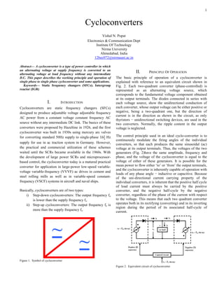
  • 1. 1 Abstract— A cycloconverter is a type of power controller in which an alternating voltage at supply frequency is converted to an alternating voltage at load frequency without any intermediate D.C. This paper describes the working principle and operation of single phase to single phase cycloconverter and some applications. Keywords— Static frequency changers (SFCs); Intergroup reactor (IGR) I. INTRODUCTION Cycloconverters are static frequency changers (SFCs) designed to produce adjustable voltage adjustable frequency AC power from a constant voltage constant frequency AC source without any intermediate DC link. The basics of these converters were proposed by Hazeltine in 1926, and the first cycloconverter was built in 1930s using mercury arc valves for converting standard 50Hz supply to single-phase Hz supply for use in ac traction system in Germany. However, the practical and commercial utilization of these schemes waited until the SCRs became available in the 1960s. With the development of large power SCRs and microprocessor- based control, the cycloconverter today is a matured practical converter for application in large-power low-speed variable- voltage variable-frequency (VVVF) ac drives in cement and steel rolling mills as well as in variable-speed constant- frequency (VSCF) systems in aircraft and naval ships. Basically, cycloconverters are of two types: i) Step-down cycloconverters: The output frequency fo is lower than the supply frequency fs. ii) Step-up cycloconverters: The output frequency fo is more than the supply frequency fs. Figure 1. Symbol of cycloconverter II. PRINCIPLE OF OPERATION The basic principle of operation of a cycloconverter is explained with reference to an equivalent circuit shown in Fig. 2. Each two-quadrant converter (phase-controlled) is represented as an alternating voltage source, which corresponds to the fundamental voltage component obtained at its output terminals. The diodes connected in series with each voltage source, show the unidirectional conduction of each converter, whose output voltage can be either positive or negative, being a two-quadrant one, but the direction of current is in the direction as shown in the circuit, as only thyristors − unidirectional switching devices, are used in the two converters. Normally, the ripple content in the output voltage is neglected. The control principle used in an ideal cyclo-converter is to continuously modulate the firing angles of the individual converters, so that each produces the same sinusoidal (ac) voltage at its output terminals. Thus, the voltages of the two generators (Fig. 2)have the same amplitude, frequency and phase, and the voltage of the cycloconverter is equal to the voltage of either of these generators. It is possible for the mean power to flow either ‘to’ or ‘from’ the output terminals, and the cycloconverter is inherently capable of operation with loads of any phase angle − inductive or capacitive. Because of the uni-directional current carrying property of the individual converters, it is inherent that the positive half cycle of load current must always be carried by the positive converter, and the negative half-cycle by the negative converter, regardless of the phase of the current with respect to the voltage. This means that each two quadrant converter operates both in its rectifying (converting) and in its inverting region during the period of its associated half-cycle of current. Figure 2. Equivalent circuit of cycloconverter Cycloconverters Vishal N. Popat Electronics & Communication Dept Institute Of Technology Nirma University Ahmedabad, India 12bec072@nirmauni.ac.in
  • 2. 2 Figure 3. Basic waveforms showing working of cycloconverter The output voltage and current waveforms, illustrating the operation of an ideal cycloconverter circuit with loads of various displacement angles, are shown in Fig. 3. The displacement angle of the load (current) is 0° (Fig. 3a). In this case, each converter carries the load current only, when it operates in its rectifying region, and it remains idle throughout the whole period in which its terminal voltage is in the inverting region of operation. In Fig. 3b, the displacement angle of the load is 60° lagging. During the first 120° period of each half cycle of load current, the associated converter operates in its rectifying region, and delivers power to the load. During the latter 60° period in the half cycle, the associated converter operates in its inverting region, and under this condition, the load is regenerating power back into the cycloconverter output terminals, and hence, into the ac system at the input side. III. SINGLE-PHASE TO SINGLE-PHASE CIRCUIT-STEP-UP CONVERTER A) Mid-point cycloconverters Figure 4. Mid-point type cycloconverter circuit It consists of a single phase transformer with mid tap on the secondary windings and four thyristors. Two of these thyristors P1 and P2 are for positive group and the other two N1 and N2 are for the negative group. Load is connected between secondary winding mid-point 0 and terminal A as shown in fig. 4. The load which is assumed to be an R Load is connected as shown. In fig. 5, during the positive half cycle both SCRs P1 and N2 are forward biased from wt=0 to wt=π. As such P1 is turned on at wt=0 so that load voltage is positive with terminal A positive and 0 negative. The load voltage now follows the positive envelope of the supply voltage, fig. 5. At instant wt1 P1 is force commutated and forward-biased thyristors N2 is turned on so that load voltage is negative with terminal 0 positive and A negative. The load or output voltage now traces the negative envelope of the supply voltage. At wt2, N2 is force commutated and P1 is turned on, the load voltage is now positive and follows the positive envelope by supply voltage. The cycle continues till wt=π. After wt=π, terminal b is positive with respect to terminal a; both SCRs P2 and N1 are therefore forward biased from wt=π to 2π. At wt=π, N2 is force commutated and forward biased SCR P2 is turned on. In this manner, thyristors P1 and N2 for first half cycle and P2 and N1 for the other half cycle and so on are switched alternately between positive and negative envelopes at a high frequency. We observe that fo=6fs and hence a step up Cycloconverter.
  • 3. 3 Figure 5. Waveform for step-up cycloconverter IV. BRIDGE - TYPE CYCLOCONVERTERS Figure 6. Bridge type cycloconverter This Cycloconverter consists of eight thyristors, P1 to P4 for positive group and the remaining four for the negative group. During the positive half cycle of the supply voltage, thyristors pairs P1, P4 and N1, N4 are forward biased from wt=0 to wt=π. At wt=0, P1 and P4 are turned on together so that the load voltage is positive with terminal A positive with respect to O. and thus load voltage traverses the positive envelope of supply voltage. At wt1 P1 and P4 are force commutated and the pair N1 and N4 is turned on. And thus the cycle repeats. At wt=π, thyristors pairs P2, P3 and N2, N3 are forward biased and thus the cycle repeats for wt=2π. In this manner, a high frequency turning-on and force commutation of pairs P1P4, N1N4 and pairs P2P3, N2N3 gives a carrier frequency modulated output voltage across load terminals. V. SINGLE-PHASE TO SINGLE-PHASE CIRCUIT-STEP- DOWN CONVERTER A single-phase to single-phase Cycloconverter is shown in fig. 6.Two full-wave fully controlled bridge converter circuits, using four thyristors for each bridge, are connected in opposite direction (back to back), with both bridges being fed from ac supply (50 Hz). Bridge 1 (P – positive) supplies load current in the positive half of the output cycle, while bridge 2 (N – negative) supplies load current in the negative half. The two bridges should not conduct together as this will produce short-circuit at the input. In this case, two thyristors come in series with each voltage source. When the load current is positive, the firing pulses to the thyristors of bridge 2 are inhibited, while the thyristors of bridge 1 are triggered by giving pulses at their gates at that time. Similarly, when the load current is negative, the thyristors of bridge 2 are triggered by giving pulses at their gates, while the firing pulses to the thyristors of bridge 1 are inhibited at that time. This is the circulating-current free mode of operation. Thus, the firing angle control scheme must be such that only one converter conduct at a time, and the changeover of firing pulses from one converter to the other, should be periodic according to the output frequency. However, the firing angles the thyristors in both converters should be the same to produce a symmetrical output. When a cycloconverter operates in the non-circulating current mode, the control scheme is complicated, if the load current is discontinuous. The control is somewhat simplified, if some amount of circulating current is allowed to flow between them. In this case, a circulating current limiting reactor is connected between the positive and negative converters, as is the case with dual converter, i.e. two fully controlled bridge converters connected back to back, in circulating current mode. The readers are requested to refer to any standard text book. This circulating current by itself keeps both converters in virtually continuous conduction over the whole control range. This type of operation is termed as the circulating- current mode of operation. The operation of the cyclo- converter circuit with both purely resistive (R), and inductive (R-L) loads is explained For resistive load, the load current (instantaneous) goes to zero, as the input voltage at the end of each half cycle (both positive and negative) reaches zero. Thus, the conducting thyristor pair in one of the bridges turns off at that time, i.e. the thyristors undergo natural commutation. So, operation with discontinuous current takes place, as current flows in the load, only when the next thyristor pair in that bridge is triggered, or pulses are fed at respective gates. Taking first bridge 1 (positive), and assuming the top point of the ac supply as positive with the bottom point as negative in the positive half cycle of ac input, the odd-numbered thyristor pair, P1 & P3 is triggered after phase delay (α1), such that current starts flowing through the load in this half cycle. In the next (negative) half cycle, the other thyristor pair (even- numbered), P2 & P4 in that bridge conducts, by triggering them after suitable phase delay from the start of zero- crossing. The current flows through the load in the same direction, with the output voltage also remaining positive. This process continues for one more half cycle (making a total of three) of input voltage (f2=f1/3= Hz). Figure 7. Input (a) and output (b) voltage waveforms of a cycloconverter with an output frequency of Hz for resistive(R) load
  • 4. 4 To obtain negative output voltage, in the next three half cycles of input voltage, bridge 2 is used. Following same logic, if the bottom point of the ac supply is taken as positive with the top point as negative in the negative half of ac input, the odd-numbered thyristor pair, N1 & N3 conducts, by triggering them after suitable phase delay from the zero- crossing. Similarly, the even-numbered thyristor pair, N2 & N4 conducts in the next half cycle. Both the output voltage and current are now negative. As in the previous case, the above process also continues for three consecutive half cycles of input voltage. From three waveforms, one combined negative half cycle of output voltage is produced, having same frequency as given earlier. The pattern of firing angle − first decreasing and the increasing, is also followed in the negative half cycle. One positive half cycle, along with one negative half cycle, constitute one complete cycle of output (load) voltage waveform, its frequency being Hz as stated earlier. The ripple frequency of the output voltage/ current for single–phase full-wave converter is 100 Hz, i.e., double of the input frequency. It may be noted that the load (output) current is discontinuous, as also load (output) voltage. For R-L load, the load current may be continuous or discontinuous depending on the firing angle and load power factor. The load voltage and current waveforms are shown for continuous and discontinuous load current in Fig. 8 and 9 respectively. Figure 8. Input (a) and output (b) voltage, and current (c) waveforms for a cycloconverter with discontinuous current In this case, the output frequency is ¼ times to that of the input frequency. So, four positive half cycles, or two full cycles of the input to the full-wave bridge converter, are required to produce one positive half cycle of the output waveform. Here the current flows even after the input voltage has reversed (after θ=π), till it reaches zero at (θ=β1) with (π+α2) > β1 > π, due to inductance being present in series with resistance, its value being low. Figure 9. Input (a) and output (b) voltage, and current (c, d) waveforms for a cyclo-converter with continuous load current. VI. MODE OF OPERATION A) Blocked Mode of Operation The operation of the Cycloconverters is explained above in ideal terms. When the load current is positive, the positive converter supplies the required voltage and the negative converter is disabled. On the other hand, when the load current is negative, then the negative converter supplies the required voltage and the positive converter is blocked. This operation is called the blocked mode operation, and the Cycloconverters using this approach are called blocking mode Cycloconverters. B) Circulating Current Mode of Operation However, if by any chance both of the converters are enabled, then the supply is short-circuited. To avoid this short circuit, an intergroup reactor (IGR) can be connected between the converters. Instead of blocking the converters during current reversal, if they are both enabled, then a circulating current is produced. This current is called the circulating current. It is unidirectional because the thyristors allow the current to flow in only one direction. Some Cycloconverters allow this circulating current at all times. These are called circulating current Cycloconverters.
  • 5. 5 Figure 10. Circulating current and IGR VII. ADVANTAGES AND DISADVANTAGES OF CYCLOCONVERTORS A) ADVANTAGES (1) In a cycloconverter, ac power at one frequency is converted directly to a lower frequency in a single conversion stage. (2) Cycloconverter functions by means of phase commutation, without auxiliary forced commutation circuits. The power circuit is more compact, eliminating circuit losses associated with forced commutation. (3) Cycloconverter is inherently capable of power transfer in either direction between source and load. It can supply power to loads at any power factor, and is also capable of regeneration over the complete speed range, down to standstill. This feature makes it preferable for large reversing drives requiring rapid acceleration and deceleration, thus suited for metal rolling application. (4) Commutation failure causes a short circuit of ac supply. But, if an individual fuse blows off, a complete shutdown is not necessary, and cycloconverter continues to function with somewhat distorted waveforms. A balanced load is presented to the ac supply with unbalanced output conditions. (5) Cycloconverter delivers a high quality sinusoidal waveform at low output frequencies, since it is fabricated from a large number of segments of the supply waveform. This is often preferable for very low speed applications. (6) Cycloconverter is extremely attractive for large power, low speed drives. B) DISADVANTAGES (1) Large number of thyristors is required in a cyclo- converter, and its control circuitry becomes more complex. It is not justified to use it for small installations, but is economical for units above 20 kVA. (2)For reasonable power output and efficiency, the output frequency is limited to one-third of the input frequency. (3) The power factor is low particularly at reduced output voltages, as phase control is used with high firing delay angle. VIII. APPLICATIONS The most interesting applications for cycloconverters are as follows : A) Variable Frequency Speed Control for AC Machines A normally input voltage with fixed frequency and amplitude is converted through a cycloconverter to an output voltage with continuously variable frequency and amplitude that is applied to the ac machine for the purpose of controlling its speed. The 3 phase cycloconverters are mainly used in ac machine drive systems running 3-phase synchronous motors, induction motors and linear motors Cycloconverters are more advantageous when used with a synchronous machine due to their output power factor characteristics. A cycloconverter can supply lagging, leading, or unity power factor loads while its input is always lagging. A synchronous machine can draw any power factor current from the cycloconverter. This characteristic operation matches the cycloconverter to the synchronous machine. On the other hand, induction machines can only draw lagging current. However, cycloconverters are used in Scherbius drives for speed control purposes driving wound rotor induction motors. The static Scherbius drives are used in very high horsepower pump and blower type applications. When cycloconverters are used to run an ac machine, the leakage inductance of the machine filters most of the higher frequency harmonics and reduces the magnitudes of the lower order harmonics B) Constant Frequency Power Supplies The function of the cycloconverter is to provide a closely regulated fixed frequency power output, from a variable frequency power source connected to its input. A typical variable speed constant frequency generating system is today based on the slip-ring ac machine. The stator of the generator is connected to a network with fixed frequency. The wound rotor is fed from a 3-phase to 3-phase cycloconverter via the slip rings. C) Controllable Reactive Power Supply for an AC System Today there is a growing demand for controllable reactive energy sources for industrial and power systems use. The cycloconverter provides controllable reactive power for the ac system to which it is connected. This will compensate the reactive power of the loads connected to the system. D) AC System Interties The cycloconverter is used to tie together two independent ac power systems of equal or different frequencies, for the purpose of controlling power flow between them. The basic idea is to use two cycloconverters in tandem, each with its input terminals connected to a common high frequency base (tuned LC tank circuit). The output terminals of the two cycloconverters are connected to the two systems to be tied.
  • 6. 6 Thus power flows from one system to the other, from the output to the input terminals of the first cycloconverter, and then from the input to the output terminals of the second cycloconverter. Both cycloconverters are naturally commutated from the voltages of the high frequency base. E) Induction Heating Systems Induction heating results from an alternating current in a coil around the metal object to be heated. The alternating magnetic field induced in the coil causes eddy currents to occur in the metal, and hese give rise to the heating effect. A naturally commutated cycloconverter operating in the inverting mode can be used to transfer power from the low- frequency 3-phase side to the high-frequency single phase side. Thus, it is possible to transfer power from the mains supply to a high-frequency induction heating load using a cycloconverter. IX. ACKNOWLEDGEMENT I would like to thank Prof. Dipesh Panchal and Prof. Bhupendra Fataniya for their guidance building the paper. X. CONCLUSION The paper expresses the working principle of cycloconverter with operation of single phase to single phase convertion. The advantages and disadvantages of cycloconverters and specific applications are highlighted. XI. REFERENCES [1] Dr. P.S. Bimbhra, “Power Electronics”, Khanna Publishers [2] “Cycloconverters”, http://goo.gl/XiwRKc [3] Wikipedia, http://en.wikipedia.org/wiki/Cycloconverter [4] NPTEL pdf, “Introduction to cyclo converters”, http://goo.gl/Npr6Gb [5] https://www.pantechsolutions.net/power-electronics/introduction-of- single-phase-to-single-phase-cycloconverter