1. NO.
A
AMENDMENT DATE
-
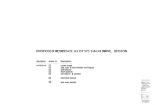
PROPOSED RESIDENCE at LOT 573 HAIGH DRIVE, BOSTON.
CLIENT
PROJECT
SCALE 1:100
Drawn Date
Scale Copyright
Project No.
Waldo
00
Sheet No.Rev.
PROPOSED RESIDENCE
AT
LOT 573 HAIGH DRIVE,
BOSTON. S.A. 5607.
M. & J. SCHUTZ
H-558
APRIL/2012
contractors are to verify all dimensions and levels on
the job before commencing any work or making
shop drawings. figured dimensions shall take
preference over scaled dimensions and any
discrepancy shall be reported to the designer
immediately.
discipline sheet no. description
architectural 00 cover sheet
01 site plan
02
03
slab layout
04
floor layouts
ACN 98 078 155 987
WISDOM in DESIGN Pty. Ltd.
Telephone 0410 558 227
17 Waymouth Avenue,
GLANDORE. S.A. 5037.
06
elevations
08
& section
& stormwater roof layout
electrical layout
wet area details
2. 8.0
39.52
154.75
73.78
73.78 181.71
+92.09
+ 89.38
+ 98.00
+ 99.90
+ 96.25
5832
11232
7316
58225
2 x 9000L rain water tanks
dp
dp
dp
dp
dp
dp
dp
dp
dp
dp
F.F.L. 98.77
T.B.M. screw in
fence post.
Adopted elevation
= 100.00
F.F.L. 98.72
F.F.L. 98.68
+98.64
+97.83
+97.68
+97.80
+97.60
+98.26
+98.05
+99.70
+97.80
overflow to existing
concrete rainwater
tank
connect to existing
aerobic waste water
disposal system
NOTE: not less than 10,000
litres of on site water shall be
clearly marked available for fire
fighting purposes.
NOTE: all above ground tanks
dedicated for fire fighting
purposes must be constructed
of non combustible material as
tested in accordance with
AS1530.1.
rainwater tanks to have total
combined capacity of 90,000 litres
2 x 9000L rain water tanks
overflow
dp
dp
dp
dp
dp
dp
dp
dp
dp
dp
BOUNDARY
181.
5832
11232
7316
58225
dp
dp
dp
dp
dp
dp
dp
dp
dp
dp
F.F.L. 98.77
F.F.L. 98.72
F.F.L. 98.68
+98.64
+97.83
+97.68
+97.80
+ 97.60
+98.26
+98.05
+99.70
+97.80
SITE PLAN
SCALE 1:1000
NOTE:
IT IS THE OWNERS RESPONSIBILITY TO
CONSULT WITH RELEVANT ELECTRICITY
SUPPLIERS WITH RESPECT TO HIGH
VOLTAGE POWER LINES
the dwelling will have installed
2 x 9000L rainwater tanks. The water
from this tank will be plumbed into the
dwelling toilets, bathrooms, kitchen,
waterheaters and laundry cold water
outlet by a licensed plumber in
accordance with AS/NZS 3500 and the
Variations published by SA Water.
use 90mmØ UPVC drains
with min. cover of 75mm
under pavement for light
trafficable areas and
100mm cover without
paving for non-trafficable
areas
provide an inspection
opening at the lowest
point of the sealed
system.
use a sealed system for
fall less than 1:200
min. fall 1:200
STORMWATER NOTES
HAIGH
DRIVE
EXISTING SHED
PROPOSED DWELLING
proposed rain water tanks
CLIENT
PROJECT
AS SHOWN @A1
Drawn Date
Scale Copyright
Project No.
Waldo
01
Sheet No.Rev.
PROPOSED RESIDENCE
AT
LOT 573 HAIGH DRIVE,
BOSTON. S.A. 5607.
M. & J. SCHUTZ
H-558
APRIL/2012
contractors are to verify all dimensions and levels on
the job before commencing any work or making
shop drawings. figured dimensions shall take
preference over scaled dimensions and any
discrepancy shall be reported to the designer
immediately.
ACN 98 078 155 987
WISDOM in DESIGN Pty. Ltd.
Telephone 0410 558 227
17 Waymouth Avenue,
GLANDORE. S.A. 5037.
ROOF STORMWATER LAYOUT
SCALE 1:200
EXISTING RAIN WATER TANK
1 in 10 Driveway gradient
1 in 10
Driveway
gradient
PART SITE PLAN
SCALE 1:100
CONSTRUCTION ISSUE
AMENDMENTNO.
A
Signed:
-
DATE
Date:
subject to council approval
3. F.F.L. 98.77
sub-board
meter box
clothes line
+98.64
+97.83
+97.68
+97.80
+97.60
+98.26
+98.05
+99.10
+ 99.30
+99.70
+98.80
+99.06
+97.80
F.F.L. 98.68
F.F.L. 98.68
14006800
9800 6840
53002490
955 3745 6800 2490 7800
3664
balcony setdown 50mm
fall to front
wet area setdown
PROVIDE ELECTRICAL
CONDUIT UNDER SLAB TO
KITCHEN ISLAND BENCH
FOR DISHWASHER.
CONCRETOR'S NOTE:-
BRICK PAVED AREA -
by client
3522
1919 1807
1917
1695
1695
1695
1917 1806
19191695
4290
16775
885
3290
4520
6880
1200
3300
4200
3053
1148
11700
9365
2040
1200
CONCRETE SLAB AS
PER ENGINEER'S
REPORT
CONCRETE SLAB AS
PER ENGINEER'S
REPORT
CONCRETE suspended deck
wet area setdown
wet area setdown
sub-board
meter box
S-FITTING
colcol
col
col col
col
col
col
col
col
col
col
col
col
col
col
sub-board
meter box
S-FITTING
down
1
3
5
7
9
11
13
15
17
THEATRE ROOM
CONCRETE decking above
outline of decking
F.F.L. 95.57
support columns
+98.64
+97.83
+97.68
+97.80
+97.60
+98.26
+ 98.05
+99.10
+99.30
+99.70
+98.80
+99.06
+97.80
8505
190 8125 190
190 2615 190 2515 190 2615 190
6260
1905880190
19015201904610190
220027001800
2405
19015201904170190
6260
CONCRETE SLAB AS
PER ENGINEER'S
REPORT
CONCRETE FILLED 200 SERIES BESSER
BLOCK WALLS AS PER ENGINEER'S REPORT
2700
2890
190 2025 190 1000 190 190
2700190
2890
9150
4720
2215 6290
store
F.F.L. 98.77
F.F.L. 98.68
3522
7800
11299 c.o.s.
BESSER BLOCK OVER
CONCRETE FOOTING
AS PER ENGINEER'S
REPORT
CONCRETE PADS AS PER
ENGINEER'S REPORT WHERE CONCRETE SLAB IS USED AS TERMITE
BARRIER:
SLAB EDGE MUST BE EXPOSED 75mm MIN.
ABOVE FINISHED EXTERNAL PAVING LEVEL FOR
TERMITE INSPECTION.
ADDITIONAL BARRIERS MUST BE PROVIDED
TO SERVICE PIPE AND OTHER PENETRATIONS IN
ACCORDANCE WITH AS 3660.1
TERMITE RISK MANAGEMENT IS TO
COMPLY WITH PART 3.1.3 BCA96 WHERE
THE CONCRETE SLAB ON GROUND OF A
TERMITE BARRIER IS TO BE AS PART
SYSTEM, THE SLAB MUST BE DESIGNED
& CONSTRUCTED TO COMPLY WITH AS
2870
SLABS MUST HAVE PENETRATIONS,
CONTROL JOINTS AND THE PERIMETER
PROTECTED
THE SLAB ON GROUND MAY BE USED AS
PERIMETER PROTECTION
PROVIDED THAT THE SLAB IS EXPOSED
75 mm ABOVE FINISHED GROUND LEVEL
AND THE SLAB EDGE DOES NOT
HONEYCOMBED, ROUGH OR CONTAIN
RIPPLES
CHEMICAL TERMITICIDE TO UNDERSIDE
OF CONCRETE SLAB IN ACCORDANCE
WITH 3660.1 (BIFLEX OR SIMILAR)
OR
STAINLESS STEEL MESH BARRIER
EITHER FULL
OR
PARTIAL PROTECTION TERMIMESH OR
SIMILAR)
OR
GRADED STONE BARRIER
OR
KORDON TERMITE BARRIER
NOTE: BUILDER TO SELECT IN
CONSULTATION WITH OWNER
NOTE:
TERMITE TREATMENT:
GROUND FLOOR SLAB LAYOUT
SCALE 1:100
CLIENT
PROJECT
SCALE 1:100
Drawn Date
Scale Copyright
Project No.
Waldo
02
Sheet No.Rev.
PROPOSED RESIDENCE
AT
LOT 573 HAIGH DRIVE,
BOSTON. S.A. 5607.
M. & J. SCHUTZ
H-558
APRIL/2012
contractors are to verify all dimensions and levels on
the job before commencing any work or making
shop drawings. figured dimensions shall take
preference over scaled dimensions and any
discrepancy shall be reported to the designer
immediately.
ACN 98 078 155 987
WISDOM in DESIGN Pty. Ltd.
Telephone 0410 558 227
17 Waymouth Avenue,
GLANDORE. S.A. 5037.
SUB - FLOOR SLAB LAYOUT
SCALE 1:100
CONSTRUCTION ISSUE
AMENDMENTNO.
A
Signed:
-
DATE
Date:
subject to council approval
4. drawers
fr
brm
wm
tr BED 1
BED 2
BED 4
BED 3
bath
verandah
KITCHEN
workshop ens.
l'dry
passage
FAMILY
LIVING
DOUBLE GARAGE
DINING
PERGOLA
wc
w.i.r.
F.F.L. 98.77
service yard
sub-board
meter box
clothes line
driveway
BED 5
robe
robe
van.
van.
shr
shr
p
1000
1000
p
desk
D/W prov.
PERGOLA
verandah
820
820
820
820
820
720
720
720
820
820
820
820
c.s.door
#
#
R/H
6.3x6.9
4.2x2.4
4.3x3.1
3.1x3.6
7.2x4.1
3.9x7.5
6.7x4.1
3.2x4.3
2.5x2.9
3.7x3.6
2.7x2.7
oven
ub
AAW 06.15
robe
bench
linen
wc
pantry
raked ceiling
bulkhead
2400Cht.
bulkhead
bulkhead
down
AAW 06.15
AAW 06.39
robe
820
c.s.door
820
c.s.door
1600wides/door
shelf
m/w
+ 98.64
+97.83
+97.68
+97.80
+97.60
+98.26
+ 98.05
+99.10
+99.30
+99.70
ASD24.27
ASD 27.27
AAW27.15
AAW27.15
AAW27.15
AAW27.15
AAW 27.15
AFG 27.15
AFG
27.15
AFG
27.15 AFG 27.15 AFG 27.15
AAW27.15
AFG27.15
AAW 27.15
ASD 27.30
AAW 27.15
ASW 18.20
AAW 12.15 AAW 18.15 AAW 27.15
ASD 27.36
ASD 27.30
ASD 27.30fullht.glasswall
1
3
5
7
9
11
13
15
17
cupb'd
Elec. HWS
Elec. HWS
retaining wall
batter
outline of theatre room
decking
1 in 10
driveway gradient
ouline of balustrade
ouline of balustrade
ouline of balustrade
boundary
T.B.M. screw in fence post.
Adopted elevation = 100.00
+98.80
+99.06
+97.80
F.F.L. 98.68
F.F.L. 98.68
14006800
9800 6840
53002490
955 3745 6800 2490 7800
3664
250
6300904900250
2503010901110903090903810
25011074039015109011002504290
1107403902700250
16541399
3053
3522
1919
1807
1917
1695
1695
1695
1917 1806
19191695
249053001400
250 9300 250
250 5810 90 1000 90 2310 90 1610 90 1810 90 3310 90
5100 250 3110 90 3610 90 4300 90
5100 7040 4500
250 2660 90 4040
3310
4290
16775
885
3290
4520
6880
1200
3300
4200
3053
1148
11700
250
3700
90
3210
250
250
2500
90
1110
90
1210
90
1910
250
3738
4415
90 1110
90
3410
250
9365
2040
300
90
1810
90
2410
250
1790
250
1200
3310
4300
90
2950
90
3610
250
110 4300 110
4195
4175
4300
110
90
4175
110
110
2943
colcol
col
col col
col
col
col
col
col
col
col
col
col
col
col
sub-board
meter box
S-FITTING
down
1
3
5
7
9
11
13
15
17
THEATRE ROOM
CONCRETE decking above
outline of decking
F.F.L. 95.57
support columns
+ 98.64
+97.83
+97.68
+97.80
+97.60
+98.26
+98.05
+98.80
+99.06
+ 97.80
8505
190 8125 190
190 2615 190 2515 190 2615 190
6260
1905880190
19015201904610190
220027001800
2405
19015201904170190
6260
CONCRETE SLAB AS
PER ENGINEER'S
REPORT
CONCRETE FILLED 200 SERIES BESSER
BLOCK WALLS AS PER ENGINEER'S REPORT
2700
2890
190 2025 190 1000 190 190
2700190
2890
9150
4720
2215 6290
store
F.F.L. 98.77
F.F.L. 98.68
3522
7800
11299 c.o.s.
BESSER BLOCK OVER
CONCRETE FOOTING
AS PER ENGINEER'S
REPORT
BUSHFIRE REQUIREMENTS
TO COMPLY WITH AS3959
ASSESSMENT
BUSH FIRE ATTACK
LOW-NO PROTECTION REQ.
CORROSION ZONE ALL
CORROSION ZONE
REQUIREMENTS FOR
CORROSION ZONE
EXTERNAL DOUBLE
BRICK TIES TO ALL
EXPOSED STEEL WORK
CORROSION ZONE
REQUIREMENTS
TO CONFIRM WITH
IN ACCORDANCE WITH
TABLES 3.3.3.1 &
3.4.4.2 OF THE BCA.
STAIR DETAIL:-
POWDERCOATED WITH TWIST
PAINTED PINE
PAINTED PINE
& BASKET DESIGN
TREADS:-
HANDRAILS:-
RISERS:-
STRINGERS:-
BALUSTRADES:- BLACK
MDF
MDF
NON-SKID STRIP TO STAIRS
AND LANDING BY OWNER
STAIR NOTE:-
STAIRS & BALUSTRADE BY
STAIRLOCK
NON SLIP FINISH OR
BALUSTRADES TO BALCONIES
AND LANDINGS TO BE IN
ACCORDANCE WITH CLAUSE
B.3 OF APPENDIX B OF THE SA
HOUSING CODE.
GROUND FLOOR LAYOUT
SCALE 1:100
CLIENT
PROJECT
SCALE 1:100@A1
Drawn Date
Scale Copyright
Project No.
Waldo
03
Sheet No.Rev.
PROPOSED RESIDENCE
AT
LOT 573 HAIGH DRIVE,
BOSTON. S.A. 5607.
M. & J. SCHUTZ
H-558
contractors are to verify all dimensions and levels on
the job before commencing any work or making
shop drawings. figured dimensions shall take
preference over scaled dimensions and any
discrepancy shall be reported to teh designer
immediately.
NOTE: wc door to be removable in
accordance with S.A. Housing Code
appendix D10.1
shown
denotes vertical control joints in
accordance with engineers details.
hard wired smoke alarms shown with 9
volt battery back-up to comply with clause 9.7
of sa housing code
#
NOTES:
All steel framing to comply with AS1538
All timber framing to comply with AS1684
All glass to comply with AS 1288
External swing doors to be fitted with draught
protection device to bottom edge of each leaf.
Hot water service shall comply with BCA 2009
part SA 3.12.5.0. a heated water service must
be designed and installed in accordance with
the waterworks act 1932 and the waterworks
regulations 1996 and BCA 2009 SA additions
SA7.
exhaust fans servicing a conditioned space shall
be fitted with a damper
ENERGY RATING NOTES:
R2.5 insulation to external living area walls
(glasswool).
R4.0 insulation to ceiling (glasswool).
R2.0 insulation to internal living area walls
(glasswool).
R1.5 insulation to internal wet area walls
(glasswool).
AREAS (m2)
APRIL/2012
ACN 98 078 155 987
WISDOM in DESIGN Pty. Ltd.
Telephone 0410 558 227
17 Waymouth Avenue,
GLANDORE. S.A. 5037.
SUB-FLOOR LAYOUT
SCALE 1:100
CONSTRUCTION ISSUE
AMENDMENTNO.
A
Signed:
12/12/12
DATE
Date:
subject to council approval
adjustments to bay windows
A
5. 2720
floor level
ceiling level
outline of balustrade
boundary
1000
floor level
ceiling level
floor level
2720
27203000
floor level
ceiling level
ceiling level
outline of balustrade
outline of balustrade
940
1090
220
2720
floor level
ceiling level
2720
floor level
ceiling level
outline of balustrade
2720
3000
floor level
floor level
ceiling level
ceiling level
outline of balustrade
boundary
999
rendered blueboard above
27203000
floor level
floor level
ceiling level
ceiling level
outline of balustrade
boundary
F.F.L. 98.77
F.F.L. 98.72 F.F.L. 98.68
F.F.L. 95.57
CALCULATIONS, ALL TO BE FORWARDED TO
MANUFACTURERS DESIGN, SPECIFICATION &
STAIRCASE DETAILS & CONNECTIONS AS PER
COUNCIL ONCE SELECTED.
SUPACEIL PLASTERBOARD
CEILING LINING GENERALLY
SUPPORT BEAM AS PER
ENGINEER'S REPORT
CORROSION PROTECTED
BRICK TIES AT MAX. 600MM
HORIZONTALLY AND 600MM
VERTICALLY TO BODY OF
WALL
masonry pier AS PER
ENGINEERS DESIGN
Approved vapour barrier,
Forticon or equal
NOTE:- ENGINEER TO DESIGN
SUSPENDED SLAB OVER SITE
CUT
CONCRETE SLAB AND FOOTING
BEAMS SHALL BE CONSTRUCTED
STRICTLY IN ACCORDANCE WITH
THE ENGINEER'S DESIGN, DETAILS
AND SPECIFICATIONS
1000H GLASS BALUSTRADE
IN NATURAL ANODISED
ALUMINIUM FRAME
R4.0 INSULATION BATTS TO
LIVING AREA CEILINGS
BOX GUTTER MIN. FALL 1 IN
100 TO OUTLET
10mm PLASTERBOARD WALL
LININGS GENERALLY
FRAMED ROOF IN
ACCORDANCE WITH TIMBER
FRAME CODE AS1684 AND
ROOF FRAMING LAYOUT
R2.0 INSULATION BATTS TO
EXTERNAL WALLS
SELECTED SKIRTING
BOARDS
SPECIFIED ROOF PURLINS AT
MAX. 1200mm MID. SPANS
AND 900mm END SPANS
VILLABOARD EAVES
LINING
1
3
5
7
9
11
13
15
17
95.50
95.00
96.00
96.50
97.00
97.50
98.00
98.50
BED 4 workshop
THEATRE ROOM
2056
stairwell
3200
SLATE GREY COLORBOND
CUSTOM ORB ROOF
400 WIDE CONCEALED BOX
GUTTERS
AG. DRAIN
NATURAL ANODISED
COMMERCIAL WINDOWS AND
DOORS
22.5 DEGREE ROOF PITCH
2700mm CEILING HEIGHT
GENERALLY
2700mm CEILING HEIGHT TO
THEATRE ROOM
RENDERED MASONRY WALLS
50mm SLAB REBATE
brick paving
concealed downpipes
900
cut line
new batter
spoon drain
AG. DRAIN
finishes schedule
RENDERED MASONRY WALLS
NATURAL ANODISED COMMERCIAL
WINDOWS AND DOORS
400mm WIDE CONCEALED BOX
GUTTERS
SLATE GREY COLORBOND CUSTOM
ORB ROOF
2700mm CEILING HEIGHT TO THEATRE
ROOM
2700mm CEILING HEIGHT GENERALLY
RAKED CEILING TO DINING AREA
22.5 DEGREE ROOF PITCH
SECTION A - A
SCALE 1:50
CLIENT
PROJECT
SCALE 1:100@A1
Drawn Date
Scale Copyright
Project No.
Waldo
04
Sheet No.Rev.
PROPOSED RESIDENCE
AT
LOT 573 HAIGH DRIVE,
BOSTON. S.A. 5607.
M. & J. SCHUTZ
H-558
contractors are to verify all dimensions and levels on
the job before commencing any work or making
shop drawings. figured dimensions shall take
preference over scaled dimensions and any
discrepancy shall be reported to teh designer
immediately.
APRIL/2012
ACN 98 078 155 987
WISDOM in DESIGN Pty. Ltd.
Telephone 0410 558 227
17 Waymouth Avenue,
GLANDORE. S.A. 5037.
CONSTRUCTION ISSUE
AMENDMENTNO.
A
Signed:
12/12/12
DATE
Date:
subject to council approval
adjustments heights of retaining walls
A
SCALE 1:100
WEST ELEVATION
EAST ELEVATION
SCALE 1:100
SCALE 1:100
NORTH ELEVATION
SOUTH ELEVATION
SCALE 1:100
6. fr
sub-board
meter box
clothes line
AAW 06.15 AAW 06.15
AAW 06.39
ASD24.27
ASD 27.27
AAW27.15
AAW27.15
AAW27.15
AAW27.15
AAW 27.15
AFG 27.15
AFG
27.15
AFG
27.15
AFG 27.15 AFG 27.15
AAW27.15
AFG27.15
AAW 27.15
ASD 27.30
AAW 27.15
ASW 18.20
AAW 12.15 AAW 18.15 AAW 27.15
ASD 27.36
ASD 27.30
ASD 27.30
sub-board
meter box
S-FITTING
D dimmer switch
1250 above floor level
light point
lived in look
home entertainment
voice data point
computer termination
LIL
HEP
point
V/D
CDP
box
sub-board
hard wired smoke alarms
shown with 9 volt battery
back-up to comply with clause
9.7 of sa housing code
meter box
reed switch
inside security sensor
HOME MANAGEMENT
SYSTEM LEGEND
KP key pad
RS
SS
fan/light
wall mounted light
telephone point
fluorescent light
2 heat/light/fan
4 heat/light/fan
exhaust fan
down light
ceiling light
ceiling
sensor
T
2 way switch
1250 above floor level
light switch
1250 above floor level
ELECTRICAL:-
television point
weatherproof p/point
single power point
double power point
2
TV
WP
TYPICAL
REFER TO ENGINEER'S REPORT FOR
FURTHER STORM WATER DETAILS.
ENGINEER'S REPORT TAKES
PREFERENCE OVER THIS DRAWING
the dwelling will have installed
2 x 9000L rainwater tanks. The water
from this tank will be plumbed into the
dwelling toilets, bathrooms, kitchen,
waterheaters and laundry cold water
outlet by a licensed plumber in
accordance with AS/NZS 3500 and the
Variations published by SA Water.
CLIENT
PROJECT
SCALE 1:100
Drawn Date
Scale Copyright
Project No.
Waldo
06
Sheet No.Rev.
PROPOSED RESIDENCE
AT
LOT 573 HAIGH DRIVE,
BOSTON. S.A. 5607.
M. & J. SCHUTZ
H-558
APRIL/2012
contractors are to verify all dimensions and levels on
the job before commencing any work or making
shop drawings. figured dimensions shall take
preference over scaled dimensions and any
discrepancy shall be reported to the designer
immediately.
ACN 98 078 155 987
WISDOM in DESIGN Pty. Ltd.
Telephone 0410 558 227
17 Waymouth Avenue,
GLANDORE. S.A. 5037.
scale 1:100
GROUND FLOOR ELECTRICAL LAYOUT
scale 1:100
SUB - FLOOR ELECTRICAL LAYOUT
CONSTRUCTION ISSUE
AMENDMENTNO.
A
Signed:
-
DATE
Date:
subject to council approval
7. DETAIL OF FLOOR/SHOWER TRAP
Drainage outlet
Drainage flange
Shower tray fixed
in accordance
specification
with manufacturers
Shower waste
Min. fall 1:60 required
Screed where
Profile
Prefabricated
Gripcove
Hob
Shower hob
(Type 1)
GripcoveCement to 1 in 60
Floor tiles on
3mm min'm flexible
sealant
screw or
Flat head
nail Gauze tape
Bitumen
Wall tiles
Selected
To join
Glued
Fall to trap
Gripcore c
Timber floor
G.I. Hob
coated with
upstand
75
100
7510
Plaster over
Brickwork
Vilaboard or
Gyprock
along
wall
Gripcove
Profile
10
25
50
75
Tap fitting
Water resistant lining board
as specified
flexible sealant 3mm-5mm wide
impervious floor surface to extend
trimmer
impervious wall surface
to 100mm min. high
waterproof tray
water resistant lining
under water resistant lining
bond breaking tape
Minimum cut-out in
wall framing to
accomodate edge of
shower base.
mortar bed
Trimmer
Flexible sealant 5 mm - 15 mm wide.
Flexible sealant 3 mm - 5 mm wide.
Impervious wall surface as specified
Bond breaking tape
Preformed shower tray
(category 2)
AND IMPERVIOUS FLOOR
JUNCTION OF IMPERVIOUS WALL
Coving coated with
Galvanised steel formed
Stud work
Bitumen and gripcore
APPLICATIONS GRIPCOVE & HOB
COVING SUITABLE FOR ALL WET AREA APPLICATIONS IN
A BITUMINOUS/PARTICULATE COATED GALVANISED STEEL
75mmmin.
sheet
Bottom wall
plate
Stud or masonry
PENETRATIONS
THROUGH WALLS
IN SHOWER AREA
SECTIONAL VIEW
PREFORMED SHOWER BASE
AND FRAMED WALL JUNCTION
with face of stud or masonry
Face of breaching piece flush
Impervious surface
THE BUILT ENVIRONMENT
SHOWER BASE SETDOWNS & FLOOR GRADIANTS.
impervious surface.
floor waste gully.
1:80min 1:60min
shower base
fixed to outside
of surfaces
shower screen
25mmmin
impervious joint
outlet
Shower waste
Min. fall 1:60
Drainage flange
Drainage outlet
max. retained water level
timber must not be used for hob
flexible sealant to
3-5mm high
waterproof memebrane
shower screen flush with
inside face of hob
waterproof memebrane to 150mm above
shower floor substrate or 25mm above the
maximum retained water level
flexible sealant to
3-5mm high
fall
flexible sealant to 3-5mm high
150mm
25mm
shower
Min. fall 1:60
Tap penetration flange
installed in accordance with
manufacturers specification
Gyprock sheets
over studs or
Plastered
brickwork
DRAINAGE FLANGE AND
MEMBRANE CONNECTION N.T.S
Screed where required
Water resistant surface material (wall) not
less then 150mm above fixture and
extending over flange
3 - 5mm flexable caulking compound
Sanitary fixture
Water resistant substrate
Water resistant surface material (wall)
3- 5mm flexible caulking
compound at the back of bench
Seal joint between fixture and
bench top to prevent moisture
penetration
Inset sanitary fixture
Seal joint between fixture and
bench top to prevent moisture
penetration
Inset sanitary fixture
Flexible caulking compound between
benchtop and window sill
Window
BENCH TOPS AND SANITARY FIXTURES ABUTTING WALLS
50mm min.
1050mm HIGH FRAME WALL WITH TIMBER
SELECTED BALUSTRADE (WHERE APPLICABLE)
MINIMUM 1050mm HIGH ABOVE TREADS OR
CAPPING AS SELECTED
MAXIMUM 120mm SPACING
SCALE 1:5
MANUFACTURERS STAIRS ARE TO COMPLY WITH PART 3.9.1 OF
BCA2005
MAX. 18 RISERS TO EACH FLIGHT
RISER MUST NOT ALLOW 125 SPHERE TO PASS THROUGH MAX.
190 mm
RISER DIMENSIONS: - MIN. 115 mm
GOING DIMENSIONS: - MAX. 355 mm MIN. 240 mm
SLOPE RELATIONSHIP: - MIN. 550 mm MAX. 700 mm
STAIR BALUSTRADE HEIGHT - MIN. 865 mm
LANDING BALUSTRADE HEIGHT - MIN. 1000 mm
BALUSTRADE MUST NOT ALLOW 125 SPHERE TO PASS THROUGH
STAIRS TO HAVE NON-SLIP FINISH OR SUITABLE NON-SKID STRIP
BALUSTRADES TO BALCONIES AND LANDINGS SHALL BE IN
ACCORDANCE WITH CLAUSE B.3 OF APPENDIX B OF THE SA
HOUSING CODE.
GOING 250 mm
3200mm
17 at 250mm
17 at 188.23mm
19mm customwood risers
TYPICAL STAIR DETAIL
25mm
GOINGS
RISERS
F / FLOOR HEIGHT
255 x 32mm stringer (closed)
255mm
BALUSTRADES TO BALCONIES SHALL BE BY
WESTSIDE IN ACCORD WITH WESTSIDE
ACCREDITED SYSTEM
STAIRS AND BALUSTRADE SHALL BE BY
STAIRLOCK IN ACCORD WITH STAIRLOCK
ACCREDITED SYSTEM
CHECK ON SITE PRIOR TO CONSTRUCTION
Customwood treads.
17 RISERS AT 188.23mm
STAIRS:
CLIENT
PROJECT
N.T.S.
Drawn Date
Scale Copyright
Project No.
Waldo
08
Sheet No.Rev.
PROPOSED RESIDENCE
AT
LOT 573 HAIGH DRIVE,
BOSTON. S.A. 5607.
M. & J. SCHUTZ
H-558
APRIL/2012
contractors are to verify all dimensions and levels on
the job before commencing any work or making
shop drawings. figured dimensions shall take
preference over scaled dimensions and any
discrepancy shall be reported to the designer
immediately.
ACN 98 078 155 987
WISDOM in DESIGN Pty. Ltd.
Telephone 0410 558 227
17 Waymouth Avenue,
GLANDORE. S.A. 5037.
CONSTRUCTION ISSUE
AMENDMENTNO.
A
Signed:
-
DATE
Date:
subject to council approval