IcedBlades - Modelling of ice accretion on rotor blades in a dynamic overall wind turbine tool V. Lehtomäki (VTT), S. Hetmanczyk, M. Durstewitz, A. Baier (Fraunhofer IWES), K. Freudenreich, K. Argyria
•
1 j'aime•1,105 vues


Recommandé
Contenu connexe
En vedette
En vedette (13)
Plus de Winterwind
Plus de Winterwind (20)
Dernier
Dernier (20)
IcedBlades - Modelling of ice accretion on rotor blades in a dynamic overall wind turbine tool V. Lehtomäki (VTT), S. Hetmanczyk, M. Durstewitz, A. Baier (Fraunhofer IWES), K. Freudenreich, K. Argyria
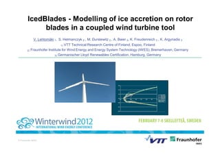
- 1. IcedBlades - Modelling of ice accretion on rotor blades in a coupled wind turbine tool V. Lehtomäki 1, S. Hetmanczyk 2 , M. Durstewitz 2 , A. Baier 2, K. Freudenreich 3 , K. Argyriadis 3 1) VTT Technical Research Centre of Finland, Espoo, Finland 2) Fraunhofer Institute for Wind Energy and Energy System Technology (IWES), Bremerhaven, Germany 3) Germanischer Lloyd Renewables Certification, Hamburg, Germany © Fraunhofer IWES
- 2. Outline • Project Motivation • Project Objectives • Cooperation and Partners • Work Packages and Schedule • Preliminary Study on Icing • Summary
- 3. Project Motivation Northern areas like Scandinavia as well as areas with high altitude feature a high potential for large capacity wind farms thanks to favourable wind conditions and mostly low populated areas. • Expansion of a common European research area by combining different research backgrounds • WinterWind 2011: R&D Priorities for cold climate (Jos Beurskens, ECN) • Impact on loading (aerodynamically and mechanical/aerodynamically induced loads, scale effects) • Impact on performance (how big are “hidden” energy losses) • Field test facilities for problem definition and verification of models • Demand for independent technical note on Figure 1: Wind energy capacity in the USA [NREL] icing (Mike Wöbbeking, GL, WinterWind 2011) Motivation Goals Partners Work packages Preliminary results Summary
- 4. Project Objectives Within the project scope a new and updated simulation tools for ice accretion on rotor blades and coupling of this tool to an aero-servo-elastic simulation tool will be developed. 1. Predicting the power losses resulting from ice accretion on rotor blades. 2. Gain a better understanding of dynamic loading effects resulting from ice accretion on rotor blades via a validated numerical models. 3. Developing a new technical note for icing sites to help wind turbine designers to take into account icing effects of rotor blades more accurately than current guidelines. 4. Development of icing classes for new edition of IEC 61400-1 Ed3 Ed4 5. Developing a method to forecast the risk of icing for single wind turbines and geographical sites 6. Forecasting power production in cold climate conditions Motivation Goals Partners Work packages Preliminary results Summary
- 5. Cooperation and Partners VTT: VTT Technical Research Centre of Finland is the biggest multitechnological applied research organisation in Northern Europe. VTT provides high-end technology solutions and innovation services. Fraunhofer IWES: Fraunhofer IWES is the leading German research institute in the field of wind energy and energy system technologies and offers a wide research spectrum from material development to grid optimization. GL: GL Renewables Certification is the leading certification body in the wind energy sector, offering project and type certifications, also in the other fields of renewable energy exploitation. WinWinD: WinWinD is an international wind energy solutions provider with a strong position in the global multi-megawatt market. Motivation Goals Partners Work packages Preliminary results Summary
- 6. Work Packages during 2012-2014 Site Conditions & Software Full-Scale Software Forecasting of Certification Development & Measurements Validation & Icing Risks Regulation Simulation Technical Note - Assessing - Adapting of - Power and load - Validation & - Developing a appropriate site TURBICE & measurements improving of method to conditions OneWind to from multi-MW simulation forecast the risk - Decision of test project WT in icing models of icing for WT turbine(s) requirements conditions - Developing of outside normal - Evaluation of - Creating an iced - Measuring of Ice classes environmental current airfoil database environmental - Developing of conditions certification with TURBICE & conditions and new ”Technical - Expanding guidelines CFD ice accretion at Note on Icing” forecast to local - Dyn. overall WT FhG IWES met site simulation utilizing mast iced rotor blades Motivation Goals Partners Work packages Preliminary results Summary
- 7. Work Packages during 2012-2014 GL Renewables Certification intends to issue a technical note which will include modelling criteria for ice aggregation on the rotor blades, design load cases and ice classes for different durations of homogeneous and inhomogeneous ice aggregation. Therefore, large scale measurements will be used to consider the following issues : • Thickness and local distribution of the ice aggregation along the blade radius and chord line resulting in changed mass distributions of the rotor blades. • Changed aerodynamics of the blade profiles due to ice aggregation resulting in altered aerodynamic loads on the rotor blade. • Inhomogeneous ice aggregation on the rotor (some blades iced, some not) leading to significant mass and aerodynamic imbalances on the rotor and thus high periodic loads. • Temporal distribution of homogeneous and inhomogeneous ice aggregation, depending on the climatic conditions. Motivation Goals Partners Work packages Preliminary results Summary
- 8. Preliminary Study on Icing Overall model Table 1: Gross Properties Chosen for the NREL 5-MW Baseline Wind Turbine • NREL – 5 MW baseline wind turbine Rated power 5 MW • Widely used in the research community Rotor Orientation, Upwind, 3Blades Icing Conditions Configuration Rotor, Hub Diameter 126 m, 3 m Table 2: Typical rime ice conditions in Scandinavia Temperature -7°C Median Volume Diameter (MVD) 25 m Liquid Water Content (LWC) 25 g/m3 Icing time 3.5 h Simulation • Ice shape from verified VTT code TURBICE and iced airfoil performance CFD results from Fluent • Iced airfoil Cl and Cd tables as input for NREL FAST • Results focusing on fatigue loads were calculated with NREL MLife – Weibull-Rayleigh distribution of wind, Vave=8.5 m/s Motivation Goals Partners Work packages Preliminary results Summary
- 9. Preliminary Study on Icing Results: Ice accretion withTurbice & CFD Turbice result 2kg/m Ice on blades causes: airfoil • Reduction of aerodynamic performance (CFD results) 3cm • Small effect to airfoil lift coefficient r/R • Larger impact on airfoil drag Accreted ice mass • Iced Cl and Cd on outer third of the blade Moderate icing (CFD results) r/R = 0.7…1.0 Additional ice mass on blades by GL Guideline =-2…-5% 2010: • Only ice mass in the current certification design load cases (no aerodynamic effects)! • For NREL blade, max ice mass with GL formula would be 40kg/m These results are used as input for • Simulation with down-scaled GL ice mass FAST simulations formula according to TURBICE result Motivation Goals Partners Work packages Preliminary results Summary
- 10. Preliminary Study on Icing Case 1: Air density increase from = 1.225 to 1.292 kg/m3, 55days/year* • Air density of 1.292 kg/m 3 at 0°C and 0 m above sea level • No ice accretion on blades • Figure below present the components that were mostly effected by air density increase Reduced component fatigue design life Reference design fatigue life** 1.000 0.980 RootMFlp1 = Blade 1 flapwise moment at the blade root 0.960 LSSGagMys = Nonrotating main bearing tilt moment 0.940 RootMFlp1 LSShftFys = Nonrotating low speed shatf shear force 0.920 TwrBsMyt = Tower base fore-aft moment LSSGagMys 0.900 LSShftFys 0.880 0.860 TwrBsMyt 0.840 * Component Ice class III determined by IEA Task 19, Recommended 0.820 Practices for Wind Energy Projects in Cold Climates, Draft, 2011 0.800 ** Reference component Miner cumulative damage , designed for 20-years of operation Motivation Goals Partners Work packages Preliminary results Summary
- 11. Preliminary Study on Icing Case 2: Comparison of Rotor ice mass and aerodynamic effects • The icing on the rotor is symmetric (all blades have same ice shape) or asymmetric (1 blade is ice-free while two other blades are iced) • Fatigue loads from aerodynamic effects are bigger than ice mass effect ** Component Component fatigue loads* vs clean [%] Mass effects Mass + Aero. effects RootMzb1 Sym. +2 +25 Asym. +1 +25 RotThrust Sym. +1 +22 Asym. 0 +22 TwrBsMyt Sym. 0 +20 Asym. 0 +19 RootMzb1 = Blade 1 pitching moment at the blade root RotThrust = Rotor thrust force TwrBsMyt = Tower base fore-aft moment *: Fatigue loads represent Damage Equivalent Loads (DELs) from load Rainflow Cycle Counting (RCC) method **: Assuming that the same ice shape will stay on the blade for the whole duration Motivation Goals Partners Work packages Preliminary results Summary
- 12. Preliminary Study on Icing Case 3: Moderate icing, symmetric icing 30days/year*, asymmetric 1day/year, • Assumtion: The ice same shape will stay on the blade for the whole duration (31 days/year) • -10…-20 % power output loss at low winds AND reduced power output quality Generator power, average Generator power, standard deviation C1=Clean (no ice) Case=Case 3 • Annual Energy Production (AEP): -13 % *: Component Ice class II determined by IEA Task 19, Recommended Practices for Wind Energy Projects in Cold Climates, Draft, 2011 Motivation Goals Partners Work packages Preliminary results Summary
- 13. Preliminary Study on Icing Case 3: Moderate icing, symmetric icing 30days/year*, asymmetric 1day/year, • Even a small amount of ice for a short period of time can effect component fatigue loads and component design life Blade root design life reduced up to -55 % Component Component design life iced vs clean airfoil RootMzb1 0.45 Increased load level at blade root (excess vibration levels) RotThrust 0.76 more stop-start sequences TwrBsMyt 0.79 RootMzb1 = Blade 1 pitching moment at the blade root increased fatigue loads RotThrust = Rotor thrust force TwrBsMyt = Tower base fore-aft moment Motivation Goals Partners Work packages Preliminary results Summary
- 14. Summary • Icing of blades causes additional wear and tear on different components • The aerodynamic effects from iced blades are more significant for the fatigue loads than accreted ice mass • Even small amounts of ice can decrease the wind turbines main component’s fatigue design life • In icing climate sites, a substantial decrease in fatigue design life (up to -55 %) is seen if no measures are taken to prevent ice accretion on rotor blades Motivation Goals Partners Work packages Preliminary results Summary
- 15. Thank you for your attention! Ville Lehtomäki VTT Technical Research Centre of Finland, Wind Energy Address: Vuorimiehentie 5, Espoo, P.O. Box 1000, FI-02044 VTT, Finland Phone: +358 40 176 3147 Fax: +358 20 722 5888 E-Mail: ville.lehtomaki@vtt.fi Sebastian Hetmanczyk Fraunhofer Institute for Wind Energy and Energy System Technology, IWES Simulation and Assessment of Wind Turbines Address: Am Seedeich 45, 27572 Bremerhaven, Germany Phone: +49 471 14290-364 Fax: +49 471 14290-111 E-Mail: sebastian.hetmanczyk@iwes.fraunhofer.de Motivation Goals Partners Work packages Preliminary results Summary