Uneak White's Personal Brand Exploration Presentation
737 electrics quiz
1. /
ELECTRICS
Mult ple-cho ce exerc se
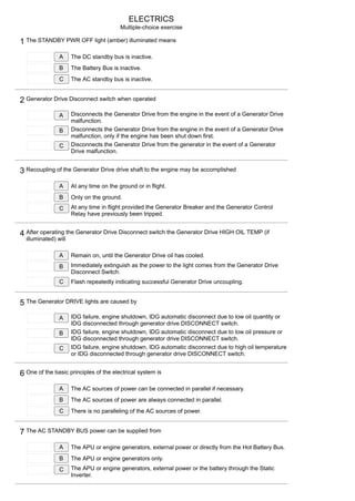
1 The STANDBY PWR OFF l ght (amber) llum nated means
A The DC standby bus s nact ve.
B The Battery Bus s nact ve.
C The AC standby bus s nact ve.
2 Generator Dr ve D sconnect sw tch when operated
A D sconnects the Generator Dr ve from the eng ne n the event of a Generator Dr ve
malfunct on.
B D sconnects the Generator Dr ve from the eng ne n the event of a Generator Dr ve
malfunct on, only f the eng ne has been shut down f rst.
C D sconnects the Generator Dr ve from the generator n the event of a Generator
Dr ve malfunct on.
3 Recoupl ng of the Generator Dr ve dr ve shaft to the eng ne may be accompl shed
A At any t me on the ground or n fl ght.
B Only on the ground.
C At any t me n fl ght prov ded the Generator Breaker and the Generator Control
Relay have prev ously been tr pped.
4 After operat ng the Generator Dr ve D sconnect sw tch the Generator Dr ve HIGH OIL TEMP ( f
llum nated) w ll
A Rema n on, unt l the Generator Dr ve o l has cooled.
B Immed ately ext ngu sh as the power to the l ght comes from the Generator Dr ve
D sconnect Sw tch.
C Flash repeatedly nd cat ng successful Generator Dr ve uncoupl ng.
5 The Generator DRIVE l ghts are caused by
A IDG fa lure, eng ne shutdown, IDG automat c d sconnect due to low o l quant ty or
IDG d sconnected through generator dr ve DISCONNECT sw tch.
B IDG fa lure, eng ne shutdown, IDG automat c d sconnect due to low o l pressure or
IDG d sconnected through generator dr ve DISCONNECT sw tch.
C IDG fa lure, eng ne shutdown, IDG automat c d sconnect due to h gh o l temperature
or IDG d sconnected through generator dr ve DISCONNECT sw tch.
6 One of the bas c pr nc ples of the electr cal system s
A The AC sources of power can be connected n parallel f necessary.
B The AC sources of power are always connected n parallel.
C There s no parallel ng of the AC sources of power.
7 The AC STANDBY BUS power can be suppl ed from
A The APU or eng ne generators, external power or d rectly from the Hot Battery Bus.
B The APU or eng ne generators only.
C The APU or eng ne generators, external power or the battery through the Stat c
Inverter.
2. /
8 A Generator Breaker can be closed
A Irrespect ve of power qual ty from the generator.
B When power qual ty from the generator s correct.
C At any t me the eng ne s runn ng at or above dle power.
9 Should a Generator Dr ve develop a fault and be d sconnected from the eng ne, before correct ve
act on s taken by the p lots
A No electr cal systems (loads) suppl ed by that generator w ll be lost as the Bus
Transfer systems suppl es all the a rcraft's electr cal systems ( loads ).
B A few non-essent al electr cal systems (loads) w ll be lost.
C All electr cal systems (loads) suppl ed by that generator w ll be lost.
10 When both eng nes are runn ng w th external power connected then
A External power must be selected OFF before the eng ne generators are brought on-
l ne.
B External power w ll automat cally d sconnect when e ther eng ne generator s
brought on-l ne.
C External power w ll automat cally d sconnect when both eng ne generators are
brought on l ne.
11 737-1/2/3/4/500: When the Generator Dr ve Temperature sw tch s selected to RISE, a h gher than
normal generator dr ve o l temperature nd cates
A An excess ve generator load or nadequate cool ng of the eng ne o l.
B An excess ve generator load or poor cond t on of the Generator Dr ve.
C Inadequate cool ng of the Generator Dr ve o l.
12 Under normal fl ght, f the Battery sw tch s selected to OFF then
A The Battery Bus s automat cally connected d rectly to the Battery.
B The Battery Bus s automat cally connected to the Hot Battery Bus.
C The Battery Bus loses power.
13 If the No. 2 TRU fa ls n the cru se
A The Master Caut on and ELEC annunc ator l ghts would llum nate.
B The Battery Ammeter would show a d scharge.
C There would be no mmed ate nd cat on.
14 The aux l ary 28V DC power receptacle s f tted
A To all ser es of 737 and s located near the Battery n the electron c compartment.
B To 737-1/2/3/4/500 only and s located near the Battery n the electron c
compartment.
C To 737NG only and s located near the Battery n the electron c compartment.
15 A fully charged battery has suff c ent capac ty to prov de power for a m n mum of
A 45 m nutes.
B 30 m nutes.
3. /
C 20 m nutes.
16 The Sw tched Hot Battery Bus s powered from
A The Hot Battery Bus whenever the Battery Sw tch s ON.
B The Battery whenever the Battery sw tch s OFF.
C The Battery Bus whenever the Battery Sw tch s OFF.
17 The APU can power both AC Busses
A On the ground, or one AC bus n-fl ght.
B In fl ght only.
C On the ground or n fl ght.
18 The T.R. voltage range s
A 28 - 30 volts.
B 24 - 30 volts.
C 26 - 35 volts.
19 The battery voltage range s
A 24 - 28 volts.
B 22 - 30 volts.
C 26 - 28 volts.
20 The TR UNIT l ght means:
A on the ground – any TR has fa led; n fl ght – TR2 or TR1 and TR3 have fa led
B on the ground – any TR has fa led; n fl ght – TR1 or TR2 and TR3 have fa led
C on the ground – any TR has fa led; n fl ght – TR3 or TR1 and TR2 have fa led
21 The Transfer Buses supply
A The Non Essent al and Heavy Loads.
B The Essent al Loads.
C The Non Essent al Loads.
22 W th the a rcraft on the ground (both eng ne generators on-l ne) and external power connected up to
the a rcraft, momentar ly pos t on ng the Ground Power sw tch to ON
A W ll tr p the r ght eng ne generator only and connect external power to the r ght
generator bus.
B W ll tr p the left eng ne generator only and connect external power to the left
generator bus.
C W ll tr p both eng ne generators and connect external power to both generator
busses.
23 If, n fl ght, both eng ne generators fa l, the APU generator should be connected to
A The No. 2 Generator Bus.
Both No. 1 and No. 2 Generator Busses.
4. /
B
C The No. 1 Generator Bus.
24 The blue GRD POWER AVAILABLE l ght when llum nated nd cates
A That the External Power Bus s powered by the ground power supply. L ght rema ns
llum nated as long as ground power s connected.
B That both Generator Busses are powered by the ground power supply. L ght
rema ns llum nated as long as ground power s connected.
C That e ther Generator Bus s powered by the ground power supply. L ght rema ns
llum nated as long as ground power s connected.
25 Under normal cond t ons the Standby AC bus s energ sed from the
A 115-volt Transfer bus No. 1.
B The Stat c Invertor.
C 115-volt Transfer bus No. 2.
26 After operat ng the Generator Dr ve D sconnect sw tch
A The Generator sw tch should be momentar ly held to OFF to tr p the Generator
Control Relay.
B The APU should be started and the APU generator selected on-l ne.
C The Standby Power sw tch should be selected to BAT.
27 The f rst act on to be taken n the event of electr cal fa lure of a generator s
A Start the APU ( f ava lable) and select t on l ne.
B Select the assoc ated Generator sw tch to OFF.
C Select the assoc ated Generator sw tch to ON.
28 The normal power source for the Battery Charger s the AC Ground Serv ce Bus, w th prov s ons for
automat c sw tch ng to
A The No. 2 Ma n Bus.
B E ther Transfer Bus.
C The No. 1 Ma n Bus.
29 Pull ng up an eng ne f re handle w ll
A Tr p the assoc ated Generator Control Relay and d sconnects the Generator Dr ve.
B Tr p the assoc ated Generator Control Relay only.
C Tr p the assoc ated Generator Control Relay and Breaker.
30 If the Battery sw tch s selected OFF, the a rsta rs can be lowered from the outs de
A By us ng the STANDBY system.
B By us ng the NORMAL system w th ground power plugged n.
C By us ng the STANDBY system, but can only be ra sed aga n by use of the
NORMAL system.
31 To have all three Generators (APU and eng nes) on-l ne s multaneously
5. /
A Is not poss ble.
B Is poss ble on the ground only.
C Is poss ble n fl ght only.
32 W th an eng ne Generator sw tch selected OFF and the assoc ated eng ne s runn ng, the voltage of
that generator w ll read
A 115 volts.
B Approx mately 3 volts.
C Res dual volts when the res dual volts sw tch s pressed.
33 To connect the External Ground power to the a rcraft's Generator busses
A The Battery sw tch must be ON.
B The Battery sw tch must be OFF.
C The Bus Transfer sw tch must be n the AUTO pos t on.
34 Standby D.C. power s normally suppl ed from
A The Hot Battery Bus.
B DC Bus No. 1.
C The Battery Bus.
35 Fa lure of the No. 1 Generator Bus w ll
A W ll cause fa lure of the System B Electr c hydraul c pump.
B W ll cause fa lure of the System A Electr c hydraul c pump.
C Have no effect on e ther electr c hydraul c pump.
36 Plac ng the BUS TRANS sw tch to 'OFF' nfl ght w th both generators operat ng and connected
A Isolates the transfer busses by prevent ng operat on of the bus transfer relay and
opens the TR 3 d sconnect relay only.
B Isolates the transfer busses by prevent ng operat on of the bus transfer relay, opens
the TR 3 d sconnect relay and prevents connect on of the battery charger to ts
alternate power source ( Ma n Bus 2 ).
C Isolates the transfer busses by prevent ng operat on of the bus transfer relay, opens
the TR 1 and 2 d sconnect relays and prevents connect on of the battery to the
Stat c Invertor.
37 Wh ch of the follow ng statements s correct
A TR 3 normally backs up TR 1 and TR 2 prov ded that the BUS TRANS sw tch s n
AUTO.
B TR 3 normally backs up TR 1 and TR 2 prov ded that the BUS TRANS sw tch s n
OFF.
C TR 3 backs up TR 2 only.
38 Standby A.C. power s ava lable on touch down after a total electr cal fa lure prov d ng
A The Battery sw tch s selected to ON and the Standby Power sw tch s selected to
AUTO.
B The Standby Power sw tch s selected to AUTO.
The Standby Power sw tch s selected to BAT.
6. /
C
39 The APU generator has
A A Generator dr ve un t wh ch w ll automat cally d sconnect when ts o l temperature
s h gh.
B A Generator dr ve un t wh ch w ll d sconnect when the APU Generator dr ve
d sconnect sw tch s act vated from the fl ght deck.
C No Generator dr ve un t s nce the APU tself s governed and w ll ma nta n a
constant generator speed.
40 If ground power s ava lable and the Ground Serv ce sw tch on the forward attendant's panel s
sw tched on, then power s suppl ed to
A The Ground Serv ce bus for ut l ty outlets, cab n l ght ng and battery charger.
B The Ground Serv ce bus for ut l ty outlets and cab n l ght ng only.
C All the a rcraft electr cal busses.
41 An eng ne electr cal generator s rated at
A 35 KVA
B 45 KVA
C 55 KVA
42 The T/R No. 3 d sconnect relay automat cally opens at gl deslope capture to
A Prov de backup power to the Standby DC bus.
B Prevent a s ngle bus fa lure from affect ng both the nav gat on rece vers and fl ght
control computers.
C Off-load the battery charger from the 115V AC GND SERVICE Bus.
43 After d sconnect ng a Generator Dr ve, ts assoc ated o l temperature nd cator
A May show an ncrease on the IN scale and/or the RISE scale.
B W ll ma nta n the same temperature read ng.
C W ll mmed ately show a decrease n temperature.
44 The Battery Sw tch must be
A ON or OFF for the GRD PWR Sw tch to be operable.
B OFF for the GRD PWR Sw tch to be operable.
C ON for the GRD PWR Sw tch to be operable.
45 The Battery Sw tch s ON and the GRD PWR s connected to the a rcraft's Busses. If the Battery
Sw tch s selected OFF then
A The GRD PWR sw tch w ll not automat cally d sconnect.
B The GRD PWR sw tch w ll automat cally d sconnect.
C The GRD POWER AVAILABLE l ght w ll ext ngu sh.