stress and strain
•Télécharger en tant que PPTX, PDF•
14 j'aime•2,577 vues

Stress and strain, types, instruments etc

Recommandé
Contenu connexe
Tendances
Tendances (20)
Similaire à stress and strain
Similaire à stress and strain (20)
Plus de COMSATS Abbottabad
Plus de COMSATS Abbottabad (20)
Dernier
Dernier (20)
stress and strain
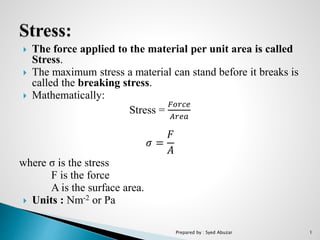
- 1. The force applied to the material per unit area is called Stress. The maximum stress a material can stand before it breaks is called the breaking stress. Mathematically: Stress = 𝐹𝑜𝑟𝑐𝑒 𝐴𝑟𝑒𝑎 𝜎 = 𝐹 𝐴 where σ is the stress F is the force A is the surface area. Units : Nm-2 or Pa Prepared by : Syed Abuzar 1
- 2. The internal force generated within the material to oppose the Mechanical deformation or relative change in shape or size of a material is known as Strain. Mathematically: Strain = 𝑒𝑥𝑡𝑒𝑛𝑠𝑖𝑜𝑛 𝑙𝑒𝑛𝑔𝑡ℎ ∈= ∆𝐿 𝐿 where ∆L = extension measured in meter. L = original length measured in meter. Strain is dimensionless quantity and has no units as it is a ratio of two lengths measured in meter. When a material is stretched, the change in length and the strain are positive. When it is compressed, the change in length and strain are negative. Prepared by : Syed Abuzar 2
- 3. Strains which involve no length changes but which do change angles is called Shear Strain. Prepared by : Syed Abuzar 3
- 4. The distance moved by any point of material in the (x,y,z) directions are denoted respectively by (u,v,w). so ∈ 𝑥= 𝜕𝑢 𝜕𝑥 ∈ 𝑦= 𝜕𝑣 𝜕𝑦 ∈ 𝑧= 𝜕𝑤 𝜕𝑧 Where ∈ is strain in x,y and z direction. Prepared by : Syed Abuzar 4
- 5. The action of stresses which will cause change in volume of the material is known as volumetric strain Volumetric strain = e = 𝑐ℎ𝑎𝑛𝑔𝑒 𝑖𝑛 𝑣𝑜𝑙𝑢𝑚𝑒 𝑜𝑟𝑖𝑔𝑛𝑎𝑙 𝑣𝑜𝑙𝑢𝑚𝑒 Consider the rectangular solid illustrated. The original shape is on the left and the deformed shape on the right. Prepared by : Syed Abuzar 5
- 6. The original volume is given by 𝑉𝑜 = ∆x∆y∆z. For the deformed body on the right, the volume is given by: V = ∆x(1+∈ 𝑥).∆y(1+∈ 𝑦). ∆z(1+ ∈ 𝑧 ) V = ∆x.∆y. ∆z(1+∈ 𝑥 +∈ 𝑦+∈ 𝑧+∈ 𝑥∈ 𝑦+∈ 𝑦∈ 𝑧+∈ 𝑧∈ 𝑥+∈ 𝑥∈ 𝑦∈ 𝑧) As strains are small, so that we can neglect all the high order terms so V ≈ ∆x.∆y. ∆z(1+∈ 𝑥 +∈ 𝑦+∈ 𝑧) V = 𝑉𝑜(1+∈ 𝑥 +∈ 𝑦 + ∈ 𝑧) Now, using the definition of volumetric strain e = 𝑉−𝑉𝑜 𝑉𝑜 = ∈ 𝑥 +∈ 𝑦 + ∈ 𝑧 Prepared by : Syed Abuzar 6
- 7. According to Hook’s law 𝑆𝑡𝑟𝑒𝑠𝑠 𝑆𝑡𝑟𝑎𝑖𝑛 = constant Where constant is known as an elastic modulus or simply a modulus. The relation of Stress and Strain within the elastic limits : 𝐸 = 𝜎 𝑎 ∈ 𝑎 𝑘𝑔/𝑚2 (1) Where E is Young’s modulus 𝜎 𝑎 is the axial stress, 𝑘𝑔/𝑚2 ∈𝑎 is axial strain, m/m Materials undergo strain when they are subject to stress. The relationship between stress and strain is different for different materials, and can be appreciated by plotting stress against strain. Prepared by : Syed Abuzar 7
- 8. Suppose the stress is tensile, and the specimen of material is stretched along x. Then, it will get thinner across the direction of stretching(y and z directions). The strains will be negative along y and z. They are related to the strain along x by a positive constant v. Prepared by : Syed Abuzar 8
- 9. Stress along x produces transverse strains: ∈ 𝑦= ∈ 𝑧= -v∈ 𝑥 Where v is known as Poisson’s ratio. From (1) ∈ 𝑦= ∈ 𝑧= -v 𝜎 𝑥 𝐸 This is true when we only have stress along x. In general, we have stress along y and z also. These other stresses will cause transverse strains also. The transverse strains along the same axis arising from different stresses simply added together. Prepared by : Syed Abuzar 9
- 10. When three stresses act, the general result is: ∈ 𝑥 = 1 𝐸 (𝜎𝑥 − 𝑣(𝜎 𝑦+𝜎𝑧)) ∈ 𝑦 = 1 𝐸 (𝜎 𝑦 − 𝑣(𝜎 𝑥+𝜎𝑧)) ∈ 𝑧 = 1 𝐸 (𝜎𝑧 − 𝑣(𝜎 𝑥+𝜎 𝑦)) In 2D, 𝜎𝑧 = 0 so: ∈ 𝑥 = 1 𝐸 (𝜎 𝑥 − 𝑣𝜎 𝑦) ∈ 𝑦 = 1 𝐸 (𝜎 𝑦 − 𝑣𝜎 𝑥) ∈ 𝑧 = −𝑣 𝐸 (𝜎 𝑥+𝜎 𝑦) Prepared by : Syed Abuzar 10
- 11. A strain gauge is a sensor whose resistance varies with applied force. It converts force, pressure, tension, weight, etc into a change in electrical resistance which can then be measured. Unit: Microstrain “change in length in 𝜇𝑚 𝑝𝑒𝑟 𝑢𝑛𝑖𝑡 𝑚𝑒𝑡𝑒𝑟 𝑜𝑓 𝑙𝑒𝑛𝑔𝑡ℎ”. Prepared by : Syed Abuzar 11
- 12. 1856: Lord Kelvin first reported on a relationship between strain and the resistance of wire conductors. 1930’s : Charles Kearns made the first notable use of bonded resistance strain gauges to measure the vibratory strains in high performance propeller blades. 1937/8 : Arthur Ruge discovered that small diameter wires made of electrical resistance alloys could be bonded to a structure to measure surface strain. 1952: At that time printing circuits were emerging, and Saunders-Roe developed the idea of making a strain gauge by etching the pattern for the gauge from a thin foil. Prepared by : Syed Abuzar 12
- 13. Based on Principles of working : 1. Mechanical 2. Electrical 3. Piezoelectric Based on Construction : 1. Wire-wound Type. 2. Foil type. 3. Semiconductor type. Prepared by : Syed Abuzar 13
- 14. Wire-wound type gauges are further classified into two types: 1. Bonded Strain Gauge A fine resistance wire diameter 0.025mm which is bent again and again as shown in diagram. This is done to increase the length of the wire so that it permits a uniform distribution of stress. This resistance wire is placed between the two carrier bases (paper, Bakelite or Teflon) which are cemented to each other. The carrier base protects the gauge from damages. Leads are provided for electrically connecting the strain gauge to a measuring instrument (Wheatstone bridge). Prepared by : Syed Abuzar 14
- 15. They are reasonably inexpensive. They can pull off overall accuracy of better than +/-0.10%. They are available in a short gauge length and have small physical size. These strain gauges are only moderately affected by temperature changes. They are extremely sensitive and have low mass. Bonded resistance strain gages can be employed to measure both static and dynamic strain. These types of strain gauges are appropriate for a wide variety of environmental conditions. They can measure strain in jet engine turbines operating at very high temperatures and in cryogenic fluid applications at temperatures as low as -452℉ (-269℃). Prepared by : Syed Abuzar 15
- 16. 2. Unbonded Strain Gauge: It consists up of wire stretched between two points in an insulating medium such as air. One end of the wire is fixed and the other end is attached to a movable element. It has preloaded resistance wires connected to a initially balanced Wheatstone bridge. Prepared by : Syed Abuzar 16
- 17. A small motion of movable base increases tension in two wires while decreasing it in two others (the wires are initially stretched enough so that they can never go slack) due to which bridge become unbalance because resistance of bridge changes. The output voltage is proportional to input displacement which can be calibrated in terms of Strain. Prepared by : Syed Abuzar 17
- 18. The arrangement of an unbonded strain gauges consists of the following. Two frames P and Q carrying rigidly fixed insulated pins as shown in diagram. These two frames can move relative with respect to each other and they are held together by a spring loaded mechanism. A fine wire resistance strain gauge is stretched around the insulated pins. The strain gauge is connected to a wheat stone bridge. Prepared by : Syed Abuzar 18
- 19. When a force is applied on the structure under study (frames P & Q), frames P moves relative to frame Q, and due to this strain gauge will change in length and cross section. That is, the strain gauge is strained. This strain changes the resistance of the strain gauge and this change in resistance of the strain gauge is measured using a wheat stone bridge. This change in resistance when calibrated becomes a measure of the applied force and change in dimensions of the structure. Prepared by : Syed Abuzar 19
- 20. Used in force, pressure and acceleration measurement. Used in places where the gauge is to be detached and used again and again. The range of this gauge is +/- 0.15% strain. This gauge has a very high accuracy. Disadvantage: It occupies more space. Prepared by : Syed Abuzar 20
- 21. The foil strain gage has metal foil on the electric insulator of the thin resin, and gage leads attached. Prepared by : Syed Abuzar 21
- 22. The strain gage is bonded to the measuring object with a dedicated adhesive. Strain occurring on the measuring site is transferred to the strain sensing element via adhesive and the resin base. For accurate measurement, the strain gage and adhesive should be compatible with the measuring material and operating conditions such as temperature, etc. Prepared by : Syed Abuzar 22
- 23. Semiconductor strain gauges are used where a very high gauge factor and a small envelope are required. They depend for their action upon piezo-resistive effect(the change in the value of the resistance due to change in resistivity). Materials: Semi-conducting materials such as silicon and germanium are used as resistive materials. Prepared by : Syed Abuzar 23
- 24. A typical semiconductor strain gauge is formed by the semiconductor technology. Semiconducting filaments of length from 2mm to 10mm and thickness of 0.05mm are bonded on suitable insulating substrates. The gold leads are usually employed for making electrical contacts. The electrodes are formed by vapour deposition. The assembly is placed in a protective box. Prepared by : Syed Abuzar 24
- 25. When the strain is applied to the semiconductor element a large change in resistance occur which can be measured with the help of a wheatstone bridge. The strain can be measured with high degree of accuracy due to relatively high change in resistance. A temperature compensated semiconductor strain gauge can be used to measure small strains of the order of micro-strain. Prepared by : Syed Abuzar 25
- 26. The gauge factor of semiconductor strain gauge is very high, about ±130. They are useful in measurement of very small strains of the order of 0.01 micro-strains due to their high gauge factor. The semiconductor strain gauge has much higher and stable output. It has long life and durable. It possesses a high frequency response of 1012 Hz. They can be manufactured in very small sizes, their lengths ranging from 0.7 to 7.0 mm. Prepared by : Syed Abuzar 26
- 27. They are very sensitive to changes in temperature. Linearity of the semi-conductor strain gauge is poor due to the higher output. Semi-conductor strain gauges are more expensive. Difficult to attach to the object under study. Limited strain range typically 3000 to 10,000 microstrain. Prepared by : Syed Abuzar 27