Bsc configuration
•Télécharger en tant que DOCX, PDF•
3 j'aime•2,103 vues

BSC configuration

Recommandé
Recommandé
Contenu connexe
Tendances
Tendances (20)
Similaire à Bsc configuration
Similaire à Bsc configuration (20)
Dernier
Dernier (20)
Bsc configuration
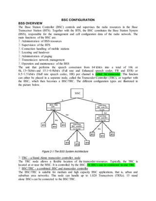
- 1. BSC CONFIGURATION BSS OVERVIEW The Base Station Controller (BSC) controls and supervises the radio resources in the Base Transceiver Station (BTS). Together with the BTS, the BSC constitutes the Base Station System (BSS), responsible for the management and cell configuration data of the radio network. The main functions of the BSC are: Administration of BSS resources Supervision of the BTS Connection handling of mobile stations Locating and handover Administration of paging Transmission network management Operation and maintenance of the BSS The unit that performs the speech conversion from 64 kbit/s into a total of 16k or 8k, 13+3kbit/s and 15.1+0.9kbit/s (Full rate and Enhanced speech coder, FR and EFR) or 6.5+1.5 kbit/s (Half rate speech codec, HR) per channel is called the transcoder. This function can either be placed in a separate node, called the Transcoder Controller (TRC), or together with the BSC, which then becomes a BSC/TRC. The different configuration types are illustrated in the picture below. TRC - a Stand Alone transcoder controller node The TRC node allows a flexible location of the transcoder resources. Typically, the TRC is located at or near the MSC. It is controlled by the BSC. 16 BSCs can be connected to one TRC. BSC/TRC - a combined BSC and transcoder controller The BSC/TRC is suitable for medium and high capacity BSC applications, that is, urban and suburban area networks. This node can handle up to 1,020 Transceivers (TRXs). 15 stand alone BSCs can be connected to the BSC/TRC.
- 2. BSC - a Stand Alone BSC without transcoders The BSC is optimized for low and medium capacity BSS networks and is a complement to the BSC/TRC, especially in rural and suburban areas. For GSM 900/GSM 1800, it can handle up to 1,020 TRXs. GPRS SYSTEM OVERVIEW An overview of the system components in the GSM system, integrated with the circuit-switched part of the GSM System, is shown in Figure 2-2. NETWORK NODES Terminal Equipment (TE) The Terminal Equipment (TE) is the computer terminal that the end-user works on. This is the component used for the GPRS system to transmit and receive end-user packet data. The TE can be, for example, a laptop computer. The GPRS system provides IP connectivity between the TE and an Internet Service Provider or Corporate LAN, connected to the GPRS system. From the TE kbit/s of view, it is possible to compare the MT to a modem that connects the TE to the GPRS system. Mobile Terminal (MT) The Mobile Terminal (MT) communicates with a TE, and over the air with a BTS. The MT must be equipped with software for the GPRS functionality when used in conjunction with the GPRS system. The MT is associated with a subscriber in the GSM system. The MT establishes a link to an SGSN. Channel reselection is provided at the radio link between the MT and the SGSN. The IP connection is static from the TE kbit/s of view, that is, the TE is not aware of being mobile and retains its assigned IP address until the MT detaches. Mobile Station (MS) The combination of a TE and an MT is an MS (Mobile Station). Often in this document as in the ETSI GSM standard for GPRS, the term MS is used when discussing the GPRS features. It can be concluded from the context which parts relate to the MT or the TE parts. Note that the MT and TE parts can co-exist in the same piece of equipment. GPRS MSs can, depending on the MS and the network capabilities, operate in three different modes: Class A mode of operation allows an MS to have a circuitswitched connection at the same time as it is involved in a package transfer.
- 3. Class B mode of operation allows an MS to be attached to both CS and PS but it cannot use both services at the same time. However, an MS that is involved in a package transfer can receive a page for circuit-switched traffic. The MS can then suspend the packet transfer for the duration of the circuit-switched connection and afterwards resume the package transfer. Class C mode of operation allows an MS only to be attached to one service at a time. An MS that only supports GPRS and not circuit-switched traffic always works in class C mode of operation. Base Station System (BSS) The Base Station System (BSS) consists of a Base Station Controller (BSC) and a Base Transceiver Station (BTS). The BTS is the radio equipment, which transmits and receives information over the air to allow the BSC to communicate with MSs in the BSCs service area. A group of BTSs is controlled by a BSC. The BTS must contain GPRS-specific software. The BSC provides all radio-related functions. The BSC has the functionality to set up, supervise, and disconnect circuitswitched and packet-switched calls. It is a high capacity switch that provides functions including handover, cell configuration data, and channel assignment. The BSC must be equipped with GPRS hardware and software when used for GPRS. One or several BSCs are served by an MSC, and a number of BSCs are served by an SGSN. The BTS separates the MS- originated circuit-switched calls from packet data communication, before the BSC forwards CS calls to the MSC/VLR, and PS data to the SGSN. The protocols towards the BSC are standard GSM protocols, for the desired compatibility. Mobile Services Switching Center (MSC) The Mobile services Switching Center (MSC) performs the telephony switching functions of the GSM circuit-switched system, as the SGSN switches the GSM packet-switched traffic. It controls calls to and from other telephony and data systems, such as the Public Switched Telephone Network (PSTN), Integrated Services Digital Network (ISDN), Public Land Mobile Network (PLMN), Public Data Networks, and, possibly, some private networks. Serving GPRS Support Node (SGSN) The Serving GPRS Support Node (SGSN) is a primary component in the GSM network using GPRS and is a new component in GSM. The SGSN forwards incoming and outgoing IP packets addressed to/from a mobile station that is attached within the SGSN service area. The SGSN provides Packet routing and transfer to and from the SGSN service area. It serves all GPRS subscribers that are physically located within the geographical SGSN service area. A GPRS subscriber may be served by any SGSN in the network, all depending on location. The traffic is routed from the SGSN to the BSC, via the BTS to the mobile station. Ciphering and authentication, Session management Mobility management Logical link management towards the MS Connection to HLR, MSC, BSC, SMS-GMSC, SMSIWMSC, GGSN Output of charging data. The SGSN collects charging information for each MS related to the radio network usage. Both the SGSN and the GGSN collect charging information on usage of the GPRS network resources. Gateway GPRS Support Node (GGSN)
- 4. Like the SGSN, the Gateway GPRS Support Node (GGSN) is a primary component in the GSM network using GPRS and it is a new component. The GGSN provides The interface towards the external IP packet networks. The GGSN, therefore, contains access functionality that interfaces external ISP functions like routers and RADIUS servers (Remote Access Dial-In User Service), which are used for security purposes. From the external IP network�s kbit/s point of view, the GGSN acts as a router for the IP addresses of all subscribers served by the GPRS network. The GGSN, thus, exchanges routing information with the external network GPRS session management; communication set-up towards external network Functionality for associating the subscribers to the right SGSNs of traffic. Output of charging data. The GGSN collects charging information for each MS, related to the external data network usage. Both the GGSN and the SGSN collect charging information on the usage of the GPRS network resources. Home Location Register (HLR) The Home Location Register (HLR) is the database that holds subscription information for every person who has bought a subscription from the GSM/GPRS operator. The HLR stores information for CS and for PS communication. The HLR contains information about, for example, supplementary services, authentication parameters, and whether or not packet communication is allowed. In addition, the HLR includes information about the location of the MS. For GPRS, subscriber information is exchanged between HLR and SGSN. Note that the authentication triplets for GPRS are fetched directly from the HLR to the SGSN, that is, it does not use the MSC/VLR like for CS GSM. For more information, see section Visitor Location Register (VLR) Functionality in SGSN and in MSC, above. The information going from the HLR to the SGSN is what the operator sets up for the subscriber. This information transfer occurs when the operator changes subscriber information, or when a new SGSN needs to have data for a subscriber after attach or roaming. The old SGSN also receives information about the roaming. The information going from the SGSN to the HLR is the routing information that is transferred upon MS action, for example, attach or roaming. For a roaming mobile, the HLR may be in a different PLMN than the SGSN serving the mobile. Gateway Mobile Services Switching Center (GMSC) The Gateway Mobile services Switching Center (GMSC) switches the circuit-switched calls between the GSM circuitswitched network and the Public Switched Telephone Network (PSTN), that is, the fixed telephony network. The GMSC is not changed for use by the GPRS system. Non-GPRS-Specific System Components Those components that are not specific to the GPRS system will only be discussed in terms of their involvement in the packet data services. Such components include, for example, the Authentication Center(AUC). Since the mobile stations use IP addresses, you can connect from the GPRS system to Internet Protocol services, obtained from an Internet Service Provider or from a Corporate LAN. The services can be, for example, World Wide Web, e-mail, or telemetry.
- 5. BSC/TRC HARDWARE AND BASIC CONCEPTS The BSC/TRC node comprises all hardware that constitute the stand alone nodes TRC and BSC, so this will be explained first. The differences are briefly described later on in the chapter. GROUP SWITCH (GS) The GS is the central part of the BSC/TRC. The GS connects an incoming channel with an outgoing channel. For example, it can connect any incoming PCM timeslot and send it out on any outgoing PCM link on any timeslot. The GS comprises Time Switch Modules (TSM) and Space switch Modules (SPM) and can switch down to 64 kbit/s. If switching should be done to lower bitrates, for example, 16 kbit/s, the SubRate Switch (SRS) must be used. Switching Network Terminal (SNT) All equipment connected to the group switch uses the same standardized interface, which is called Switching Network Terminal (SNT). The SNT is a software concept and represents the software connection of the physical hardware to the Group Switch. The hardware is normally referred to as device hardware. Each SNT is connected to the GS at a Switching Network Terminal Point (SNTP). In Figure 2-3, the following device hardware is shown, which will be further explained in the chapter: Exchange Terminal Circuit (ETC) Signaling no.7 terminal (ST7, C7-ST) Transcoder and Rate Adaptor (TRA) Transceiver Handler (TRH) Subrate Switch(SRS) Device (DEV) As previously mentioned, the hardware connected to the GS is referred to as device hardware. A device is the resource that each SNT has connected to the GS. Depending on what device hardware and what software is loaded the device can have different capabilities. The devices and their names will be explained under each device hardware. EXCHANGE TERMINAL CIRCUIT (ETC) The ETC board is the common hardware in the AXE to handle the PCM transmission links, in this case between the MSC-BSC and BSC-RBS. The links can either be 1.5 Mbit/s (T1) or 2 Mbit/s (E1) PCM links. The two link types use different hardware, that is, for BYB 501, which is the latest building practice, the 1.5 Mbit/s uses ETC-T1 boards and the 2 Mbit/s uses ETC5
- 6. boards. What differs, though, between the ETC boards towards the MSC and those towards the RBSs, is that they have different software loaded. This means that the resources are named differently. Figure 2-4 shows the different names and concepts connected to the PCM links in an E1 system. ETRALT and ETRBLT Figure 2-4 illustrates two types of SNTs: The ETRALT and the ETRBLT use the same type of hardware (ETC), but they are loaded with different types of software. This means that they have slightly different functions. The SNT concept supervises everything from the connection to the GS, the SNTP, to the output from the ETC board. The Digital Path (DIP) then takes over the supervision of the PCM link. Digital Path (DIP) Digital Path (DIP) is the name of the function used for supervision of the connected PCM lines. ITU-T has issued recommendations which state how the PCM links should be supervised. All these recommendations are implemented in the DIP function and the ETC. Depending on whether the PCM link goes toward the MSC or the RBS the DIP will have different names. RALT towards the MSC and RBLT towards the RBSs. RBLT stands for RTS A- Bis interface Line Terminal whereas RTS stands for Radio Transmission & Transport Subsystem. RALT stands for RTS A-interface Line Terminal. RBLT Devices Each Time Slot (TS), which is 64 kbit/s, on the PCM link towards the RBS is called an RBLT device. The device is a resource that the BSC can store information on. In this case it is either LAPD signaling or speech towards the RBS. The number of RBLT devices is 32 on an E1 PCM link and 24 on a T1 PCM link. Figure 2-4 illustrates an E1 PCM system. The numbering of the RBLT devices starts from 1 to 31 for the first DIP RBLT-0. This is written as - 1&&-31, where the "&&" stand for how to specify a range of numbers in an AXE command. It should also be noted that the RBLT devices 0, 32, 64, and 96 are not used. It is TS 0 on the PCM link that is used for synchronization and which, therefore, cannot be used for other purposes. This is not the case in a T1 PCM link, where synchronization is performed differently.
- 7. In the T1 system, the devices are also called RBLT24 devices. There is a more detailed explanation of what the RBLT devices can be used for in the A-bis chapter. RALT Devices Each Time Slot (TS), which is 64 kbit/s, on the PCM link towards the MSC is called an RALT device. The device is a resource that the BSC can store information on. In this case, it is either C7 signaling or speech towards the MSC. The numbering principle of the RALT devices are the same as for the RBLT devices. ETC 155 MBIT/S ETC 155 hardware can be used for connecting different switches to the SDH transport network. The interface may be optical fibers or electrical cables. DESCRIPTION The SDH (Synchronous Digital Hierarchy) standard was originally introduced into transmission networks (now called transport networks). Now, the BSC can be connected via SDH to the MSC. ETC 155 is an SDH interface, supporting both electrical (155.52 MHz) and optical (1310 nm) communication. The ET155 terminates an STM1 (Synchronous Transfer Mode) and contains 63 E1/T1. The ETC 155 is not a part of the SDH network but is connected to the SDH network. TRANSCODER AND RATE ADAPTOR (TRA) The TRA is the function responsible for the speech coding and rateadaption of incoming speech and data from the MSC and the RBS. The hardware where the function is implemented is called Transcoderand Rate Adaption Board (TRAB). It has the following basic functions: Transcoding of speech information. Speech at 64 kbit/s to/from the MSC is transcoded to 13 kbit/s to/from the RBS enabling four compressed channels to be multiplexed onto one 64 kbit/s channel. This is if Full Rate (FR) or Enhanced Full Rate (EFR) is used, which have a bit rate of 13/15.1 kbit/s. For Half Rate (HR) speech is transcoded to 6.5 kbit/s Additional control information, 3 kbit/s for FR, 0.9 for EFR, and 1,5 kbit/s for HR, is added to the transcoded rate towards the RBS giving a final output of 16 kbit/s or 8 kbit/s. The control information which is called in-band signaling, basically tells what type of information the information contains, for example, speech, data. Rate adaptation of data information. The maximum data rate supported at present in GSM is 14.4kbit/s per TS. With High Speed Circuit Switched Data (HSCSD) it is possible to have higher bit rates, since then the MS will be assigned more than one TS. Discontinuous Transmission (DTX) functions on both uplink and downlink. This reduces the interference in the network and saves mobile batteries.
- 8. Figure 2-6 illustrates how the TRA works. The incoming 64 kbit/s is sent through the GS to the TRA. Four 64 kbit/s channels are transcoded to 16 kbit/s (FR and EFR) and multiplexed onto one 64 kbit/s. They are then sent out via the GS to the RBS on the Abis interface on an RBLT device. Multiplexing and Demultiplexing of Channels The transcoder multiplexes a number of transcoded channels into one 64 kbps channel, used between the BSC and BTS. The number of multiplexed channels depends on the type of speech codec: Four traffic channels for FR or EFR. Eight traffic channels for HR. In terms of hardware, a TRA-EM consists of 32 devices, requires 32 GS inlets, and can handle 24 TCHs. In an FR or EFR TRA-EM: Six MUXs handle 24 multiplexed channels towards the BTS. 24 DEMUXs handle the demultiplexed channels towards the MSC. Four DEMUXs are statically connected to each MUX device. In an HR TRA-EM: Three MUXs handle 24 multiplexed channels towards the BTS. 24 DEMUXs handle the demultiplexed channels towards the MSC.
- 9. Eight DEMUXs are statically connected to each MUX device. In both configurations, two TRABs are used (for TRAU type TRA R4). The relation between a TRA-EM and an SNT is one to one. The connection and disconnection of a transcoder device to and from an SNT is performed by command. Furthermore, a printout of transcoder device states and transcoder-SNT connections can be obtained by command. Before the transcoder equipment can be seized for a connection towards the BTS, it must be physically and logically connected, and manually deblocked. The transcoder equipment requested can be either semi-permanently connected or seized in a transcoderpool: Transcoder devices can be semi-permanently connected through the GS for FR only. Once the connection is established, it is possible to use it for traffic as soon as synchronization is established between the transcoder and the BTS. Pooled transcoder devices are seized according to TRA capability and availability. The connections through the GS, for a transcoder device seized in a transcoder pool, are set up on a per call basis. TRA Devices and SNT Each SNT in Figure 2-6 has 30 devices, for example, SNT -> RTTF1S1-0 has devices RTTF1D1-2&&-31. From this you can deduce, using Figure 2-9 below, that this is TRA R5 hardware, with an FR speech version. The number of 64kbit/s that can be transcoded on this type of TRA is 24. They are called demultiplexed (DEMUX) devices. The other six devices are called multiplexed (MUX) devices. One MUX device is 16kbit/s (FR and EFR) and a DEMUX device is 64 kbit/s. Transcoders in Pool and
- 10. Semi-permanently Connected Transcoders The transcoder devices can either be in a pool or be semipermanently connected. If they are semi-permanently connected, the transcoder device is always connected to the same TS in the RBS. This means that the resource is not accessible for others, even if there is no ongoing traffic. One TRA device is required for each air TS, which will require a lot of TRA boards. To put the transcoders in a pool,transcoders are seized on a per call basis leading to better utilization of the installed transcoder hardware. Figure 2-10 illustrates how the TRA in pool generally works and the hardware that is involved. In this configuration of the transcoder, the TRA resources can be set to be �pools�. In one BSC/TRC there can be different pools, for example, one pool with EFR devices, one with FR devices, and one with HR devices. Depending on what MS equipment should be connected, the BSC/TRC seizes a device that is dependent on each MS's capabilities, for example, not all MSs can handle EFR, and releases the device when the call is terminated. This results in less hardware being required, since all people in the BSC area will not call simultaneously. There is seldom congestion, due to no available TRA devices in the pool. To be able to handle semi- permanently connected transcoders, there is no need for extra hardware. However, if "transcoders in pool" are going to be used, the BSC/TRC must have a Subrate Switch (SRS). The reason for this is that different TRA resources, for example, FR and EFR, are mixed onto the same 64 kbit/s, and the GS (as previously mentioned) cannot switch lower than 64kbit/s. The SRS can switch down to 8 kbit/s and can then put different 16 kbit/s devices on the same 64 kbit/s. The SRS function is explained below. TRANSCEIVER HANDLER (TRH) The TRH performs the activities that are required to control the RBS and the transceivers, and is responsible for a multitude of functions including: Handling of signaling on the Link Access Protocol on the Dchannel (LAPD) link between BSC-BTS. Handling of logical channel addressing part of signaling to/from the BTS and mobile stations (MS). Processing of measurement data from the BTS and MSs
- 11. Operation and maintenance of the BTS. Figure 2-11 illustrates the principle of the TRH. TRH Devices and SNT Each SNT in Figure 2-11 has 32 devices. The SNT, in this case, is called RHSNT and it handles the TRH devices, named RHDEV. Each transceiver in the RBS must have a signaling connection towards the BSC. The device handling the signaling connection towards the RBS is the RHDEV. One RHDEV is semipermanently connected to one transceiver in the RBS. As previously mentioned, the RHSNT has 32 devices, but in reality only 24 of them are usable (RPG2). This is due to the fact that one TS is used for test purposes and the others are excluded so as not to load the TRH with tasks. That is why the numbering in the picture states RHDEV- 1&&-24 and RHDEV-33&&-56. The TRH that is explained above, is the latest TRH which uses Regional Processor Group (RPG) hardware. The older hardware that uses Regional Processor Device (RPD) hardware has only eight RHDEVsper board, seven of which can be used. The LAPD protocol is explained further in the A-bis chapter. SUBRATE SWITCH (SRS) Subrate switching allows for the connection of rates lower than 64 kbit/s. The rates allowed are n*8 kbit/s (where n=1->7). An example of how the SRS can be used to switch calls to different destinations using only one TRA resource is illustrated in Figure 2-12. Four 64 kbit/s timeslots that contain speech arrive at the BSC from the MSC. The TRH controls the call set-up and determines whether the SRS should be used, which TRA should be used, the call type, destination BTS, etc. The GS sets up connections to the TRA which transcodes the four 64 kbit/s channels into four 16 kbit/s. The 4x16 kbit/s channels are then multiplexed into one 64 kbit/s channel which is returned to the GS. In this example, the destination of two of the calls is BTS1, and of the other two calls, BTS2. The TRH has this information and determines that it is necessary to set up a connection towards the SRS. The SRS switches the 16 kbit/s subrate channels to two 64 kbit/s channels that are returned to the GS. Hereafter, the GS can set up connections towards BTS1 and BTS2, which contain the correct subratechannels.
- 12. The SRS is required when TRA in pool is used. In addition, it is needed when utilizing LAPD multiplexing, which occurs when the speech and signaling towards the RBS is multiplexed onto the same 64kbit/s. This will be explained further in the A-bis chapter. SIGNAL TERMINAL NO.7 (ST7) The MSC must have the ability to signal with the BSC. This is done using Signaling Terminals (ST). The signaling devices are called, for example, C7ST2C for E1 PCM links. The signaling between the MSC and BSC is slightly different in a T1 network, since T1 has a separate signaling network. This means that there is no connection between the GS and the ST. Generally, there are two signaling TSsbetween the BSC and MSC. Whereas one is sufficient for all signaling, the second is installed for redundancy purposes. PROCESSORS (RP AND CP) The RPs are designed to execute simple high-repetition functions and are mainly used for the direct control of the hardware units of the application systems. These hardware-units offer the traffic devices of the exchange, for example, ETC, TRA. The CPs execute complex and data demanding tasks. The standard RPs are called either RPM6A or RP4, but there are a few other types. Regional Processor Device (RPD) The RPD device hardware can supply TRH or C7 signaling and is integrated with the RP. Regional Processor Group (RPG) The RPG has the same functionality as the RPD, but it has higher capacity than the RPD. The RPG, with different software loaded, can, in the BSC, serve as TRH, C7, or STC terminal. STAND ALONE TRC AND BSC TRC The Transcoder Controller (TRC) node contains the pooled transcoder resources and is a stand alone node.
- 13. The TRC is connected to the MSC via the A-interface and to the BSC via the A-Ter Interface. The TRC node has the ability to support up to 16 BSCs over the A-ter interface. The transcoders in the variousTRAnscoder (TRA) pools in a TRC can be shared between all BSCs, associated with the TRC. One of the connected BSCs may be residing on the same physical platform as the TRC, that is, in a combined BSC/TRC network element. One TRC can be connected to up to four MSCs. This makes it possible to build rather large TRCs supporting several MSCs. One BSC is still controlled by one specific MSC. The TRC can contain several transcoder resource pools, one pool per type of transcoder resource, for example, Full Rate, Enhanced Full Rate, and Half Rate. The A-interface signaling remains unchanged in the new system structure. For the communication between the TRC and a remote BSC, a C7 based Ericsson proprietary communication protocol is used. Concerning a combined BSC/TRC, internal signalingbetween the TRC and BSC part is used. The TRC node handles the A-ter transmission interface resources. The operation and maintenance signaling and the handling of the A-ter interface are similar to the current implementation on the A-interface. At call set-up and after signaling connection set-up, an assignment request is sent via the MSC to the BSC. The request is sent directly to the BSC and can pass transparently through the TRC. The BSC receives the assignment request and requests a transcoder device from the TRC, also indicating the Ainterface Circuit Identification (CIC) to be used for this specific call. The TRC allocates a transcoderdevice and the time slot on the A- ter interface, which is connected to the A-interface CIC, specified by the MSC. The TRC replies to the BSC, which establishes the connection to the mobile. BSC The stand alone BSC has been developed and optimized especially for rural and suburban areas and is a complement to the BSC/TRC node in the BSC product portfolio. The BSC contains the SRS and TRH, as previously explained. The BSC, however, does not contain any transcoders. It utilizes transcoder resources from a central BSC/TRC, or from a TRC node. The BSC is connected to the BSC/TRC, or the TRC via the A-ter interface.
- 14. PCM LINK DEVICE TYPES Figure 2-15 illustrates the different names of the PCM link devices in the three types of BSS implementation. BTS is also referred to as the radio base station (RBS), node B (in 3G Networks) or, simply, the base station (BS). For discussion of theLTE standard the abbreviation eNB for evolved node B is widely used.