Doppler VHF Omni Directional Range (DVOR)
•Télécharger en tant que PPTX, PDF•
33 j'aime•34,138 vues

Doppler vhf omni directional range (dvor) is navigational aid that is used to help the aircraft find its route.

Recommandé
Recommandé
Contenu connexe
Tendances
Tendances (20)
Similaire à Doppler VHF Omni Directional Range (DVOR)
Similaire à Doppler VHF Omni Directional Range (DVOR) (20)
Plus de Afghanistan civil aviation institute
Plus de Afghanistan civil aviation institute (6)
Dernier
Dernier (20)
Doppler VHF Omni Directional Range (DVOR)
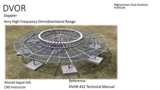
- 1. DVOR Doppler Very High Frequency Omnidirectional Range Afghanistan Civil Aviation Institute Ahmad Sajjad Safi CNS Instructor Reference: DVOR 432 Technical Manual
- 2. Introduction to DVOR The DVOR is a radio navigation aid recommended by the ICAO and introduced internationally for short and medium range aircraft guidance. The DVOR radio navigation equipment is a further development of the conventional VOR. • Todays airway network is marked by a number of DVOR ground beacons operating in the 108...118 MHz VHF frequency range and having a transmission range of 300 km.
- 4. DVOR Propagated Information Using the VOR receiver installed in the aircraft the pilot is able to obtain the following information from a DVOR radio navigation installation: - The azimuth indication of the aircraft’s position relative to the ground beacon, i.e. the angle between magnetic North and the direction ground beacon to aircraft. -The bearing which indicates whether the aircraft is flying to the left or right of the preselected course (position line) or whether it is exactly on it. -The "from/to" indication which shows whether the aircraft is flying toward the DVOR beacon or away from it.
- 5. DVOR Propagated Information To evaluate the indications only a map is required, and the knowledge of the DVOR positions and a DVOR frequency chart. The aircraft position is marked by the intersection of two position lines in the cockpit DVOR indicator.
- 6. DVOR Propagated Information When flying ±30° vertical elevation over a DVOR a loss of signal is experienced as the aircraft passes through the “CONE OF SILENCE.
- 7. Operational use of DVOR DVOR located at or near an airport not only provides bearing information for an approach to that airport, but also provides en-route bearing information to aircraft overflying or using the airway on which the DVOR is serving. A number of DVOR’s are therefore placed along the airways to provide continuous bearing information. En-route navigation with DVOR, principle
- 8. Principles of the DVOR The principle on which the DVOR operates is based on the measurement of the phase angle difference of two 30 Hz signals radiated by the station at the same time. One signal (reference signal) is radiated with the same phase in all directions. For the second 30 Hz signal (variable signal), the phase of signal is variable. The electric phase angle measured in the airborne receiver to identify the azimuth angle. This bearing (azimuth) angle also known as RADIALS will be displayed on DVOR indicator inside the cockpit.
- 9. Principles of the DVOR Azimuth as a function of the phase angle.
- 10. Principles of the DVOR Reference Signal : the 30 Hz modulation which amplitude−modulates (AM) the VHF carrier now acts as the reference signal. The modulated carrier signal is transmitted Omni directionally by a center antenna. It is amplitude−modulated with the voice (300...3000 Hz) and the identity Morse code in addition to the 30 Hz reference signal. Variable Signal: the 30 Hz modulation which frequency−modulated (FM) 30 Hz modulation (variable signal) is contained in the 9960 Hz subcarrier. The 9960 Hz subcarrier signal is transmitted directionally by a sideband radiator antenna, which can be considered to be rotating along a circular path. The radiated sideband frequency is offset by +9960 Hz or −9960 Hz with respect to the carrier frequency. ICAO stipulated ±480 Hz signal in order to obtain the frequency deviation.
- 11. Principles of the DVOR Frequency spectrum of the DVOR radio beacon:
- 12. General Information of the DVOR The main features of DVOR 432 is as follows: Compliance with ICAO standards. Available as single or dual equipment with power up to 50 W or 100 W. Microprocessor controlled transmitter and monitoring system. Modular design, extensive common use of subassemblies within the Navaids. Local LCD display and control panel for system status indication, basic controls and measurement of data. Standard PC used as local or remote interface (via RMMC) between the system and the operator.
- 13. Operational use of DVOR The DVOR system can be combined with a DME, TACAN and VORTAC. These symbols denotes beacon installation on an aeronautical chart.
- 14. Operational use of DVOR • The DVOR system can be combined with a to form a DVOR/DME station. Then an aircraft can determine its position by referring to the location of a single DVOR/DME station. DME Antenna
- 15. Principles of the DVOR