

Recommandé
Contenu connexe
Tendances
Tendances (18)
En vedette
En vedette (14)
Similaire à Barrier mtl5517 d i b
Similaire à Barrier mtl5517 d i b (20)
Dernier
Dernier (20)
Barrier mtl5517 d i b
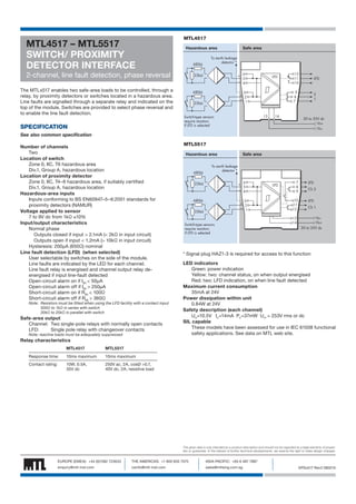
- 1. MTL4517 – MTL5517 SWITCH/ PROXIMITY DETECTOR INTERFACE MTL4517 Hazardous area To earth leakage detector * 680W 2-channel, line fault detection, phase reversal Safe area + 6 22kW LFD 5 – 4 The MTLx517 enables two safe-area loads to be controlled, through a relay, by proximity detectors or switches located in a hazardous area. Line faults are signalled through a separate relay and indicated on the top of the module. Switches are provided to select phase reversal and to enable the line fault detection. SPECIFICATION 680W 1 13 Switch-type sensors require resistors if LFD is selected LFD 9 8 7 3 + 2 – 22kW 12 11 10 14 2 1 20 to 35V dc Vs+ Vs– See also common specification Number of channels Two Location of switch Zone 0, IIC, T6 hazardous area Div.1, Group A, hazardous location Location of proximity detector Zone 0, IIC, T4–6 hazardous area, if suitably certified Div.1, Group A, hazardous location Hazardous-area inputs Inputs conforming to BS EN60947–5–6:2001 standards for proximity detectors (NAMUR) Voltage applied to sensor 7 to 9V dc from 1kΩ ±10% Input/output characteristics Normal phase Outputs closed if input > 2.1mA (< 2kΩ in input circuit) Outputs open if input < 1.2mA (> 10kΩ in input circuit) Hysteresis: 200μA (650Ω) nominal Line fault detection (LFD) (when selected) User selectable by switches on the side of the module. Line faults are indicated by the LED for each channel. Line fault relay is energised and channel output relay deenergised if input line-fault detected Open-circuit alarm on if Iin < 50μA Open-circuit alarm off if Iin > 250μA Short-circuit alarm on if Rin < 100Ω Short-circuit alarm off if Rin > 360Ω Note: Resistors must be fitted when using the LFD facility with a contact input 500Ω to 1kΩ in series with switch 20kΩ to 25kΩ in parallel with switch Safe-area output Channel: Two single-pole relays with normally open contacts LFD: Single pole relay with changeover contacts Note: reactive loads must be adequately suppressed MTL5517 Hazardous area 680W Safe area To earth leakage detector * + 6 22kW LFD 5 – 4 680W 3 + 2 – 1 22kW Switch-type sensors require resistors if LFD is selected 7 8 9 10 11 12 LFD Ch 2 LFD Ch 1 Vs– Vs+ 13 14 20 to 35V dc * Signal plug HAZ1-3 is required for access to this function LED indicators Green: power indication Yellow: two: channel status, on when output energised Red: two: LFD indication, on when line fault detected Maximum current consumption 35mA at 24V Power dissipation within unit 0.84W at 24V Safety description (each channel) Uo =10.5V Io =14mA Po =37mW Um = 253V rms or dc SIL capable These models have been assessed for use in IEC 61508 functional safety applications. See data on MTL web site. Relay characteristics MTL4517 MTL5517 Response time: 10ms maximum 10ms maximum Contact rating: 10W, 0.5A, 35V dc 250V ac, 2A, cosØ >0.7, 40V dc, 2A, resistive load The given data is only intended as a product description and should not be regarded as a legal warranty of properties or guarantee. In the interest of further technical developments, we reserve the right to make design changes. EUROPE (EMEA): +44 (0)1582 723633 THE AMERICAS: +1 800 835 7075 ASIA-PACIFIC: +65 6 487 7887 enquiry@mtl-inst.com csinfo@mtl-inst.com sales@mtlsing.com.sg EPSx517 Rev2 080210