1. 1
Description and Application
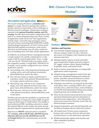
The award-winning FlexStat is a controller and
sensor in a single, attractive package that creates a
flexible solution to stand-alone control challenges or
BACnet network challenges. Temperature sensing is
standard with optional humidity, motion, and CO2
sensing. Flexible input and output configurations and
built-in or custom programming ensure that a variety
of application needs can be met. Such applications
include single- and multi-stage packaged, unitary,
and split systems (including high SEER/EER variable
speed packaged equipment), as well as factory-pack-
aged and field-applied economizers, water-source
and air-to-air heat pumps, fan coil units, central sta-
tion air handling units, and other similar applications.
In addition, an on-board library of programs permits
a single model to be rapidly configured for a wide
range of HVAC control applications. Thus, a single
“one size fits all” FlexStat model can replace multi-
ple competitor models. A single BAC-120163CW, for
example, can be quickly configured for any of these
application options:
◆ Air handling unit, with proportional heating and
cooling valves, and with optional economizer,
dehumidification, and/or fan status
◆ Fan coil unit, 2-pipe or 4-pipe, proportional or
2-position valves, with optional dehumidification
(w/ 4-pipe option) and/or fan status
◆ Heat pump unit, with up to two compressor
stages, and with optional auxiliary heat, emer-
gency heat, dehumidification, and/or fan status
◆ Roof top unit, with up to two H/C stages, and
with optional economizer, dehumidification, and/
or fan status
FlexStats also provide the capability to customize the
standard library of sequences using a KMC program-
ming tool (BACstage or TotalControl). This enables a
local authorized KMC installing contractor to adapt
the standard library to the unique site needs and ap-
plication-specific requirements of a particular project.
BACnet over MS/TP communication is standard.
“E” versions, with an RJ-45 jack, add BACnet over
Ethernet, BACnet over IP, and BACnet over IP
as Foreign Device (for communication across the
Internet).
Specifications and design subject to change without notice.
BAC-12xxxx/13xxxx/14xxxx Series
FlexStat™
Features
Interface and Function
◆ User-friendly English-language menus (no
obscure numeric codes) on a 64 x 128 pixel,
dot-matrix LCD display with 5 buttons for data
selection and entry
◆ Multiple display options include selectable
space temperature display precision, degrees
F/C toggle, rotation values, display blanking,
hospitality mode, and locked mode
◆ Built-in, factory-tested libraries of configurable
application control sequences
◆ Integral energy management control with opti-
mum start, deadband heating and cooling set-
points, and other advanced features to assure
comfort while maximizing energy savings
◆ Schedules can easily be set uniquely by the entire
week (Mon.–Sun.), weekdays (Mon.–Fri.), week-
end (Sat.–Sun.), individual days, and/or holidays;
six On/Off and independent heating and cooling
setpoint periods are available per day
◆ Three levels of password-protected access (user/
operator/administrator) prevent disruption of
operation and configuration—plus Hospitality
mode and Locked User Interface mode offer ad-
ditional tamper resistance
◆ Integral temperature and optional humidity, mo-
tion (shown in photo above), and/or CO2
sensors
◆ All models have 72-hour power (capacitor)
backup and a real time clock for network time
synchronization or full stand alone operation
◆ Models functionally replace most Viconics and
other competitors’products
(Shown with
Optional
Motion and
Humidity
Sensors)
2. 2
Features (Cont.)
Inputs
◆ Six analog inputs for additional configurable
remote external sensors, such as remote space
temperature (with averaging, highest, and low-
est options), remote CO2
, OAT, MAT, DAT, water
supply temperature, fan status, and other sensors
◆ Inputs accept industry-standard 10K ohm (Type
II or III) thermistor sensors, dry contacts, or 0–12
VDC active sensors
◆ Input overvoltage protection (24 VAC, continuous)
◆ 12-bit analog-to-digital conversion on inputs
Outputs
◆ Nine outputs, analog and binary (relays)
◆ Each short-circuit protected analog output
capable of driving up to 20 mA (at 0–12 VDC)
◆ The NO, SPST (Form “A”) relays carry 1 A max.
per relay or 1.5 A per bank of 3 relays (relays 1–3
and 4–6) @ 24 VAC/VDC
◆ 8-bit PWM digital-to-analog conversion on out-
puts
Installation
◆ Backplate mounts on a standard vertical 2 x
4-inch wall handy-box (or, with an HMO-10000
adapter, a horizontal or 4 x 4 handy-box), and the
cover is secured to the backplate by two con-
cealed hex screws
◆ Two-piece design provides easy wiring and instal-
lation (see the Dimensions and Connectors section)
Connections
◆ Screw terminal blocks, wire size 14–22 AWG, for
inputs, outputs, power, and MS/TP network
◆ “E” versions add an RJ-45 jack
◆ A four-pin EIA-485 (formerly RS-485) data port
on the underside of the case enables easy tempo-
rary computer connection to the BACnet network
(access with a KMD-5624 cable—requires use of
KMD-5576 or third-party interface)
BACnet Communication and Standards
◆ Integral peer-to-peer BACnet MS/TP LAN net-
work communications on all models (with con-
figurable baud rate from 9600 to 76.8K baud)
◆ “E” versions add BACnet over Ethernet, BACnet
over IP, and BACnet over IP as Foreign Device
◆ Meets or exceeds BACnet AAC specifications in
the ANSI/ASHRAE BACnet Standard 135-2008
Configurability
I/O
◆ Up to 10 analog input objects (IN1 is space tem-
perature, IN2–IN4 and IN7–IN9 are 0–12 VDC in-
puts, IN5 is reserved for humidity, IN6 is reserved
for motion detection, IN10 is reserved for CO2
)
◆ Up to 9 analog or binary output objects
Value
◆ 100 analog value objects
◆ 100 binary value objects
◆ 40 multi-state value objects (with up to 16 states
each)
Program and control
◆ 10 PID loop objects
◆ 10 program objects (contains a library of 5 built-
in programs and customized Control Basic
programming in the other 5 program objects can
be done through BACstage or TotalControl)
Schedules and trends
◆ 2 schedule objects
◆ 1 calendar object
◆ 8 trend objects, each of which holds 256 samples
Alarms and events
◆ 5 notification class (alarm/event) objects
◆ 10 event enrollment objects
Dimensions and Connectors
5.551
(141)
BAC-12xxxx
Dimensions in
Inches (mm)
4.192 (106)
1.125
(28.6)
EIA-485 Data Port for
Quick Network Access
Terminal Blocks
on Removable
Backplate for
Easy Wiring
NOTE: Two-piece design allows field rough-in
and termination of field wiring to the
backplate without needing the FlexStat at
the site—permitting FlexStats to be bulk-
configured off-site and plugged into the
wired backplates at a later time if desired.
3. 3
Models
If your application is a:
◆ FCU (Fan Coil Unit) or Packaged Unit, AHU (Air
Handling Unit), or RTU (Roof Top Unit)—see all
models
◆ HPU (Heat Pump Unit)—see the BAC-1xxx63CW
models only
Model* Outputs** Optional Sensors*** Typical Applications
BAC-12xxxx models (e.g., BAC-120036CW) are standard and do not have a CO2
sensor. BAC-13xxxx/14xxxx models (e.g., BAC-140036CW)
have CO2
sensors to add Demand Control Ventilation to the applications below. DCV is only available when using an AHU, RTU, or HPU
application with a modulating economizer option enabled. See “Specifications, CO2 Models Only” for more information.
BAC-1x0036CW
3 Relays and
6 Analog Outputs
None
• 1H/1C, fan, and 6 universal outputs
• 3-speed fan, 2- or 4-pipe FCUs with modulating valves
• Central station AHUs with modulating/1/2 Heat/Cool
• Variable-speed fan output
• Single-stage applications
BAC-1x0136CW Humidity****
• Same as BAC-1x0036CW
• Dehumidification sequence
• Humidification sequence (AHU or 4-pipe FCU)
BAC-1x1036CW Motion/Occupancy
• Same as BAC-1x0036CW
• Occupancy-based operation
BAC-1x1136CW
Humidity and
Motion/Occupancy****
• Same as BAC-1x0136CW
• Occupancy-based operation
BAC-1x0063CW
6 Relays and
3 Analog Outputs
None
• 1 or 2 H and 1 or 2 C, fan
• Multi-stage packaged or split systems
• Multi-stage heat pumps with or without factory-packaged economizers
• Central station AHUs with modulating Heat/Cool
• 3-speed fan, 2- or 4-pipe FCUs with modulating or 2-position valves
BAC-1x0163CW Humidity****
• Same as BAC-1x0063CW
• Dehumidification sequence (AHU, 4-pipe FCU, or RTU)
BAC-1x1063CW Motion/Occupancy
• Same as BAC-1x0063CW
• Occupancy-based operation
BAC-1x1163CW
Humidity and
Motion/Occupancy****
• Same as BAC-1x0163CW
• Occupancy-based operation
*The standard color is white. To order the optional light almond color, remove the “W” at the end of the model number
(e.g., BAC-121163C instead of BAC-121163CW). To order the IP version, add an E after the C (e.g., BAC-121163CEW).
All models have a real-time clock.
**Analog outputs produce 0–12 VDC @ 20 mA maximum, and relays carry 1 A max. per relay or 1.5 A per bank of 3 relays
(relays 1–3, 4–6, and 7–9) @ 24 VAC/VDC.
***All models have a 32-bit processor, an internal temperature sensor, and 6 analog inputs. All models have optional discharge air
temperature monitoring/trending and fan status monitoring. Optional sensors include humidity, motion, and CO2
.
****In models with CO2
sensors, humidity sensors come standard.
For more details, see the Application/Model Selec-
tion Guide on the next page.
Product and Documentation Awards
◆ Gold medal in the Networked/BAS category of
Consulting-Specifying Engineer magazine’s Product
of the Year competition (September 2010)
◆ Editors’ Choice product in Commercial Building
Products (October 2010)
◆ Winner in the HVAC & Plumbing category of
Green Thinker Network’s Sustainability 2012 com-
petition (April 2012)
◆ FlexStat support documents also won an Award
of Merit in the 2009–2010 publications competi-
tion sponsored by the Chicago Chapter of the So-
ciety for Technical Communication (April 2010)
4. 4
Application/Model Selection Guide
NOTE: For more details, see the Models section on the previous page. For details about the CO2
model
options, see the Specifications, CO2
Models Only section on page 6.
BAC-1x0063CW
BAC-1x0163CW
(+Humidity)
BAC-1x1063CW
(+Motion)
BAC-1x1163CW
(+Humidity/Motion)
BAC-1x0036CW
BAC-1x0136CW
(+Humidity)
BAC-1x1036CW
(+Motion)
BAC-1x1136CW
(+Humidity/Motion)
Packaged Unit (Air Handling Unit and Roof Top Unit)
1 Heat and 1 Cool X X X X
1 or 2 Heat and 1 or 2 Cool (in RTU Menu Only) RTU RTU RTU RTU
1 or 2 Heat and Modulating Cool X X X X
Modulating Heat and 1 or 2 Cool X X X X
Modulating Heat and Modulating Cool (in AHU Menu Only) AHU AHU AHU AHU X X X X
Opt. Outside Air Damper, Modulating X X X X X X X X
Opt. Outside Air Damper, 2 Position (in RTU Menu Only) RTU RTU RTU RTU X X X X
Opt. Fan Speed Control X X X X
Opt. Dehumidification X X X X
Opt. Humidifier X X
Opt. Motion/Occupancy Sensor X X X X
Opt. CO2 Sensor with DCV (Demand Control Ventilation)
Opt. IP/Ethernet BACnet Communications
FCU (Fan Coil Unit)
2 Pipe, Modulating X X X X X X X X
2 Pipe, 2 Position X X X X
4 Pipe, Modulating X X X X X X X X
4 Pipe, 2 Position X X X X
Opt. Dehumidification (4 pipe only) X X X X
Opt. Humidifier (4 pipe only) X X
Opt. Motion/Occupancy Sensor X X X X
Opt. CO2 Sensor with DCV (Demand Control Ventilation)
Opt. IP/Ethernet BACnet Communications
HPU (Heat Pump Unit)
Opt. Outside Air Damper, Modulating X X X X
Opt. Dehumidification X X
Opt. Motion/Occupancy Sensor X X
Opt. CO2 Sensor with DCV (Demand Control Ventilation)
Opt. IP/Ethernet BACnet Communications
Model Code for BAC-1xmhra CEW:
BAC = BACnet Device r = Number of Relay Outputs (3 or 6)
1 = Model Series a = Number of Analog Outputs (3 or 6)
x = CO2 Sensor Type (3 or 4) or None (2) C = Real-Time Clock (RTC standard on all models)
m = Motion Sensor (1) or None (0) E= IP/Ethernet Communications Option (no E = MS/TP only)
h = Humidity Sensor (1) or None (0) W = White Color (no W = light almond)
NOTE: All models have a real-time clock (see Model Code). On models with a CO2 sensor, the humidity sensor is standard and
Demand Control Ventilation is only available when using an AHU, RTU, or HPU application with a modulating economizer option
enabled. For the differences between the types of CO2 sensors in the BAC-13xxxx and BAC-14xxxx, see page 6. The BAC-12xxxxx
has no CO2 sensor.
N/A
BAC-13xxxx or BAC-14xxxx (see Note below)
Add an E to the model number: BAC-1xxxxxCEx (see Model Code)
DCV N/A for FCU applications, but CO2 levels still displayed
Add an E to the model number: BAC-1xxxxxCEx (see Model Code)
With 3-speed fan
1 or 2 compressors with auxiliary and emergency heat
BAC-13xxxx or BAC-14xxxx (see Note below)
Add an E to the model number: BAC-1xxxxxCEx (see Model Code)
Applications and Options
3 Relays and 6 Analog Outputs6 Relays and 3 Analog Outputs
FlexStat Models
5. 5
Supply Voltage 24 VAC (+20%/–10%), Class 2
Supply Power 13 VA (not including relays)
Outputs (3/6 or 6/3) Binary outputs (NO, SPST,
Form “A” relays) carry 1 A max.
per relay or a total of 1.5 A per
bank of 3 relays (relays 1–3 and
4–6) @ 24 VAC/VDC
Analog outputs produce 0–12
VDC, 20 mA maximum
External Inputs (6) Analog 0–12 VDC (active, pas-
sive contacts, 10K thermistors)
Connections Wire clamp type terminal
blocks; 14–22 AWG, copper
Four-pin EIA-485
(Opt.) eight-pin Ethernet jack
Display 64 x 128 pixel dot matrix LCD
Case Material White (standard) or light al-
mond flame-retardant plastic
Dimensions* 5.551 x 4.192 x 1.125 inches
(141 x 106 x 28.6 mm)
Weight* 0.48 lbs. (0.22 kg)
Approvals* UL 916 Energy Management
Equipment; FCC Class B, Part
15, Subpart B and complies
with Canadian ICES-003 Class
B; BTL listing pending
Humidity Sensor (optional internal)
Sensor Type CMOS
Range 0 to 100% RH
Accuracy @ 25°C ±2% RH (10 to 90% RH)
Response Time Less than or equal to 4 seconds
Temperature Sensor (without humidity sensor)
Sensor Type Thermistor, Type II
Accuracy ±0.36° F (±0.2° C)
Resistance 10,000 ohms at 77° F (25° C)
Operating Range 48 to 96° F (8.8 to 35.5° C)
Temperature Sensor (with humidity sensor)
Sensor Type CMOS
Accuracy ±0.9° F (±0.5° C) offset from
40 to 104° F (4.4 to 40° C)
Operating Range 36 to 120° F (2.2 to 48.8° C)
Environmental Limits*
Operating 34 to 125° F (1.1 to 51.6° C)
Shipping –22 to 140° F (–30 to 60° C)
Humidity 0 to 95% RH (non-condensing)
Specifications, General Specifications, Motion Sensor
Motion/Occupancy Sensor Detection Performance
For more details about operation of the motion sen-
sor, see the FlexStat Application Guide.
Motion Sensor (Opt.) Passive infrared with approx.
10 meter (32.8 feet) range
55°
X
0°
Top View
(10 m)
32.8 ft
(10 m)
32.8 ft
(10 m)
32.8 ft
(10 m)
32.8 ft
55°
X
0°
Top View Side View
0°
46.5°
Y
(10 m)
32.8 ft
(10 m)
32.8 ft
(10 m)
32.8 ft
(10 m)
32.8 ft
*NOTE: Except for CO2
sensor models—see the next page for those specifications.
6. 6
5.551
(141)
CO2
Sensor BAC-13xxxx BAC-14xxxx
Applications For zones with occupied/unoccupied times* For zones with continuous occupancy*
Method Non Dispersive Infrared (NDIR), with ABC Logic* Non Dispersive Infrared (NDIR), dual channel*
Calibration Self-calibrates over several weeks* Self-calibrates approximately once every 24 hours*
Typical Life of Sensor 15 years 10 years
Measurement Range 400 to 2000 ppm 0 to 2000 ppm
Accuracy (at nominal
operating temperature)
±35 ppm @ 500 ppm, ±60 ppm @ 800 ppm,
±75 ppm @ 1000 ppm, ±90 ppm @ 1200 ppm
±75 ppm or 10% of reading (whichever is greater)
Altitude Correction Configurable from 0 to 32,000 feet
Pressure Dependence 0.135 of reading per mm Hg
Temperature Dependence 0.2% FS (full scale) per °C
Stability < 2% of FS over life of sensor < 5% of FS or < 10% reading annual over life of sensor
Response Time < 2 minutes for 90% step change typical
Warm Up Time < 2 minutes (operational) and 10 minutes (maximum accuracy)
*The BAC-13xxxx series has been certified to comply with CA Title 24, Section 121(c), as well as sub-paragraph 4.F. See explanations below.
Specifications, CO2
Models Only
Dimensions 5.551 x 5.192 x 1.437 inches
(141 x 132 x 36.5 mm)
Weight 0.5 lbs. (0.28 kg)
Environmental Limits
Operating 34 to 122° F (1.1 to 50° C)
Shipping –22 to 140° F (–30 to 60° C)
Humidity 0 to 95% RH (non-condensing)
Approvals UL 916 Energy Management
Equipment; FCC Class A, Part
15, Subpart B and complies
with Canadian ICES-003 Class
A; BTL listing pending
NOTE: The CO2
models are not approved for
residential applications.
Dimensions in
Inches (mm) 5.192 (132)
1.437
(36.5)
The BAC-13xxxx series uses Automatic Background
Calibration Logic, or ABC Logic, a patented self-
calibration technique designed to be used in appli-
cations where concentrations will drop to outside
ambient conditions (approximately 400 ppm) at
least three times in a 14 day period, typically dur-
ing unoccupied periods. With ABC Logic enabled,
the sensor will typically reach its operational accu-
racy after 25 hours of continuous operation if it was
exposed to ambient reference levels of air at 400 ±10
ppm CO2
. The sensor will maintain accuracy speci-
fications with ABC Logic enabled, given that it is at
least four times in 21 days exposed to the reference
value and this reference value is the lowest concen-
tration to which the sensor is exposed. ABC Logic
requires continuous operation of the sensor for peri-
ods of at least 24 hours.
NOTE: The BAC-13xxxx series, with ABC Logic, has
been certified to comply with CA Title 24,
Section 121(c), as well as sub-paragraph 4.F
that specifies accuracy will be maintained
within tolerance for a minimum of 5 years
without recalibration and that a detected
sensor failure will cause the controller to
take appropriate corrective action.
The BAC-14xxxx series, for zones with continuous
occupancy, has a dual channel sensor. A CO2
chan-
nel measures gas concentration, and a reference
channel measures the sensor signal intensity. Self-
calibrations are performed approximately every 24
hours using the reference channel. During the self-
calibration the sensor ppm reading is frozen and will
not react to changing CO2
.
NOTE: See also the Demand Control Ventilation
(DCV) section on the next page.
NOTE: See the previous page for specifications in
common with other models.
7. 7
Although BAC-12xxxx FlexStats do not have a built-
in CO2
sensor, they still have DCV control sequences
available. When DCV is enabled in these models,
IN9 is assumed to be connected to an external KMC
SAE-10xx CO2
sensor. BAC-13xxxx/14xxxx FlexStats
also have the external sensor option, and if used, the
highest of the two readings (internal vs. external)
will be used to control DCV sequences. The CO2
ppm display (when enabled) also shows the highest
of the two levels.
NOTE: The three DCV Configuration graphs
on the left show the DCV component
of the signal to the outside air damper.
Depending on the conditions and the DCV
configuration, the signal to the damper
might be controlled by Minimum Position,
Economizer Loop, or other components.
The maximum of these component values
is used, not the sum of them. (If there is a
Low Limit alarm, however, these signals
are overridden, and the damper is closed.)
NOTE: DCV is only available when using an
AHU, RTU, or HPU application with a
modulating economizer option enabled.
Without that configuration, DCV will
not appear in menus, but the CO2
ppm
readings will (unless turned off in the User
Interface menu) still show on the lower
right of the display.
The graph below shows an example of how a cool-
ing setpoint and the outside air damper position
could be efficiently controlled by a FlexStat’s built-in
combination of schedule, motion sensor (configured
for occupancy standby and occupancy override),
and CO2
sensor (configured for Advanced DCV).
When using applications with a modulating econo-
mizer option, the three types of Demand Control
Ventilation (DCV) configurations available are:
◆ Basic—Provides simple DCV, modulating the
outside air damper in direct response to the cur-
rent CO2
level with respect to its setpoint. Basic
DCV is much
more energy
efficient than
no DCV at
all, while
maintain-
ing adequate
IAQ (Indoor
Air Quality).
It is the easi-
est DCV method to configure. However, where
VOCs, radon, or other pollutants become exces-
sive during unoccupied times (with no ventila-
tion), the FlexStat’s Standard or Advanced DCV
configuration is recommended.
◆ Standard—When the BAC-13xxxx settings are
properly configured, this complies with CA Title
24, Section
121(c). This
would also
apply to a
properly
configured
BAC-12xxxx
with a remote
SAE-10xx CO2
sensor. Stan-
dard DCV, under most conditions, is somewhat
less energy efficient than Basic, but it enhances
IAQ.
◆ Advanced—When the settings are properly
configured, this configuration complies with
CA Title 24,
Section 121(c)
and ASHRAE
Standard
62.1-2010 and
follows guide-
lines by Port-
land Energy
Conservation,
Inc. (PECI).
Although Advanced DCV is the most complex to
configure, it is more energy efficient than Stan-
dard while still optimizing IAQ.
Demand Control Ventilation (DCV)
Night Flush
(Economizer
Cooling) Startup*
Normal
Occupancy
Standby*
Cooling
Setpoint
Scheduled
On Time
OAD
Position
Scheduled
Off Time
(Unoccupied) (Occupied)
Occupancy
Override*
(*Available only on FlexStats with motion sensors)
Standby
Recovery
(Manual)
Override
Pre-purge
(Unoccupied)
CO2
Setpoint
0%
Space CO2
CO2
Maximum
DCV Signal
Component
to OAD
100% Basic DCV Configuration
CO2
Base
Outside Air
Damper
Position
Component
CO2
Setpoint
OA Full
OA Area
0%
Space CO2
CO2
Maximum
DCV Signal
Component
to OAD
100% Standard DCV Configuration
CO2
Base
Outside Air
Damper
Position
Component
“Basic” Signal
“Standard”
Signal
OA Max
OA Full
OA Area
0%
Space CO2
CO2
Maximum
DCV Signal
Component
to OAD*
100% Advanced DCV Configuration
CO2
Base
Outside Air
Damper
Position
Component
*Under Normal
Vent Mode operation
(see Vent Mode description)
For more details about DCV configuration and
operation, see the FlexStat Operation Guide and
FlexStat Application Guide.