1. CONFIDENTIAL
TECHNICAL INFORMATION BULLETIN July 26, 2000
EXCAVATORS 320C (ANB, BCB, BBC, BDB, BDC,
ALF, BEF, AKH, BER, BPR, BRX,)
EXCAVATORS
COMPONENT CODE(S) xxxx
SUBJECT: HYDRAULIC POWER TEST FOR AKASHI BUILT 320C
PROBLEM:
This is an optional pump flow test to measure hydraulic
horsepower. This test was not available at first ship of the
320C.
SOLUTION:
This test is performed by measuring the pump flow at the
boom cylinders. This test measures the combined horsepower
level of the engine and the hydraulic systems. .
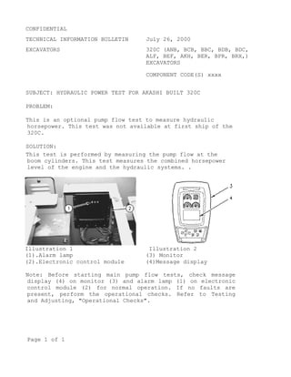
Illustration 1 Illustration 2
(1).Alarm lamp (3) Monitor
(2).Electronic control module (4)Message display
Note: Before starting main pump flow tests, check message
display (4) on monitor (3) and alarm lamp (1) on electronic
control module (2) for normal operation. If no faults are
present, perform the operational checks. Refer to Testing
and Adjusting, "Operational Checks".
Page 1 of 1
2. Illustration 3 Flow meter tool layout(6) 6V-9746 O-Ring
seal (7) Line (right boom cylinder head end) (8) Line (right
boom cylinder rod end) (9) Line (left boom cylinder rod end)
(10) 4C-9910 Portable hydraulic tester (flow meter) (11)
Line (left boom cylinder head end) (12) 6V-8716 Seal
connector (13) Left boom cylinder (14) Right boom cylinder
(15) 6V-9832 Cap (31) 5P-0201 Hose (32) 5P-1010 Sleeve (33)
4C-8767 Coupling (34) 7M-8485 O-Ring seal (35) 4C-6481
Coupler assembly (36) 4C-6482 Nipple assembly (37) 4I-6141
Coupling (38) 8C-9026 Adapter (39) 6K-6307 O-Ring seal (40)
6V-9511, (41) 6V-9746
Page 2 of 2
3. Illustration 4 Circuit diagram (5) Main control valve, (9)
Line (left boom cylinder rod end), (10) 4C-9910 Portable
hydraulic test (flow meter1) (11) Line (left boom cylinder
head end)(13) Left boom cylinder (14) Right boom cylinder
(15) 6V-9832 Cap (17) Pressure tap (right pump delivery
pressure) (18) Pressure tap (left pump delivery pressure)
(19) Tap (power shift pressure) (20) 8T-0861 Pressure gauge
(21) Engine (22) Multitach (23) Right pump (24) Left pump
(42) 8T-0856 Pressure gauge
Note Care must be taken to ensure that fluids are contained
during performance of inspection, maintenance, testing,
adjusting and repair of the product. Be prepared to collect
the fluid with suitable containers before openingany
compartment or disassembling any component containing
fluids.
Refer to Special Publication, NENG2500, “Caterpillar
Tools and Shop Products Guide” for tools and supplies
suitable to collect and contain fluids on Caterpillar
products.
Page 3 of 3
4. Dispose of all fluids according to local regulations and
mandates.
1. Position the machine on level ground.
Illustration 5 Illustration 6 (7) Line (right
boom cylinder head end) (8) Line
(right boom cylinder rod end)
(9) Line left boom cylinder rod
end) (11) Line left boom
cylinder head end) 13 Left boom
cylinder (14) Right boom
cylinder
2. Fully retract the stick cylinder rod. Adjust the
position of the bucket so that the bucket is parallel to
the ground. Lower the boom until the bucket is flat on
the ground. Refer to Illustration 5.
3. Stop the engine.
4. Release the pressure in the hydraulic system. Refer to
Testing And Adjusting, "Hydraulic System Pressure -
Release".
5. Install the following tools in accordance with the flow
meter tool layout and the circuit diagram. Refer to
Illustration 3 and Illustration 4.
a. Disconnect lines (7), (8), (9), and (11) from boom
cylinders (13) and (14).
Page 4 of 4
5. Illustration 7 (15) 6V-9832 Cap
b. Install caps (15) to the open end of the connectors at
boom cylinders (13) and (14).
c. Connect portable hydraulic tester (10), test hoses and
fittings between line (9) and line (11). Line (11) must
be connected to the inlet side of portable hydraulic
tester (10). Line (9) must be connected to the outlet
side of portable hydraulic tester (10).
d. Plug lines (7) and (8) with plug (40) and seal (41).
Illustration 8 (17) Pressure tap
(right pump delivery pressure) (18)
Pressure tap (left pump delivery
pressure) (19) Pressure tap (power
shift pressure) 23 Right pump (24) Left
pump
e. Connect a 6000 kPa (870 psi) pressure gauge (20) to the
power shift pressure tap (19).
f. Connect a 60000 kPa (8700 psi) pressure gauge (20) to
pressure tap (17) for right pump delivery pressure.
g. Connect a 60000 kPa (8700 psi) pressure gauge (20) to
pressure tap (18) for right pump delivery pressure.
Page 5 of 5
6. h. Install multitach (22) on engine (21).
6. Obtain a fuel sample and determine the fuel API rating.
The fuel API rating will be used in order to calculate the
corrected hydraulic horsepower. See Table 5.
To prevent personal injury or equipment
damage from failure of the hydraulic
test equipment or associated circuit
components because of blocked pump
flow, make sure that the test equipment
valves are fully open before starting
the engine.
To prevent personal injury and/or
equipment damage from failed lines or
comoponents while the hydraulic test
equipment is returned to the open flow
position, slowly open the hydraulic
test equipment valve while monitoring
the pump flow.
If pump flow does not increase as the
valve is opened, shut the engine off
and determine what is preventing the
pump from upstroking.
7. Start the engine.
8. Place the machine controls at the following settings:
engine speed dial "10" and AEC switch OFF. Refer to
Testing And Adjusting, "Engine Performance Test" for
engine rpm settings.
9. Place the hydraulic activation control lever in the
UNLOCKED position.
10. Increase the hydraulic oil temperature to the
recommended temperature range. Refer to Table 1 and Table
Page 6 of 6
7. 2 for the recommended operating temperatures of the
hydraulic oil.
11. Slowly move the joystick for the boom to the full BOOM
RAISE position. Hold the joystick for the boom in this
position until the pump flow test is completed.
Illustration 9 Portable
hydraulic tester (flow meter)
12. Turn valve (26) on portable hydraulic tester (10)
clockwise until the pressure gauge reads 15700 kPa (2300
psi). Record the pump flow at the pressure specification
in Table 1 and Table 2.
Table 1
Pump Flow Test At 15700 kPa (2300 psi)1
Flow Measured Flow Meter
(liter/min.
Pump delivery Pump
pressure (kPa)
(1)
The recommended hydraulic oil temperature
for this pressure range is 50 to 55° (120
to 130°) . The hydraulic oil temperature
will increase quickly during this test.
Collection of data should begin when the
temperature reaches 50° C (120°F)
Page 7 of 7
8. Table 2
Standard Pump Flow Test At 29400 kPa (4250 psi)2
Flow Measured Flow Meter
(liter/min.
Pump delivery Pump
pressure (kPa)
(2)
The recommended hydraulic oil temperature
for this pressure range is 50 to 57° (120
to 135°) . The hydraulic oil temperature
will increase quickly during this test.
Collection of data should begin when the
temperature reaches 50° C (120°F)
13. Use the data in Table 1, the data in table 2 and the
following formula in order to calculate the hydraulic
horsepower.
Case 1: Metric System
KW = [(Pf + Pr)/2 _ Q/60000]_ Cr _ Cf _ Ca
Cf = 1 - 0.004 _ (40 - Tf)
Ca = 1 - 0.0014 _ (25 - Ta)
KW : Hydraulic power
Pf (kPa) : Pump pressure (front)
Pr (kPa) : Pump pressure (rear)
Q (Lpm) : Hydraulic oil flow rate
Cr : Correction factor of fuel gravity (refer to
the above table)
Cf : Correction factor of fuel temperature
Tf (C°) : Fuel temperature in fuel filter
(Ambient temperature + 10) can be used.
Ca : Correction factor of inlet air
Ta (C°) : Air temperature at air cleaner inlet
(Ambient temperature + 10) can be used.
Page 8 of 8
9. Case 2: English System
HP = [(Pf + Pr)/2 _ Q/1714] _ Cr _ Cf _ Ca
Cf = 1 - 0.004 _ (40 - Tf)
Ca = 1 - 0.0014 _ (25 - Ta)
HP : Hydraulic horsepower
Pf (psi) : Pump pressure (front)
Pr (psi) : Pump pressure (rear)
Q (gpm) : Hydraulic oil flow rate
Cr : Correction factor of fuel gravity (refer to
the above table)
Cf : Correction factor of fuel temperature
Tf (C°) : Fuel temperature in fuel filter
(Ambient temperature + 10) can be used.
Ca : Correction factor of inlet air
Ta (C°) : Air temperature at air cleaner inlet
(Ambient temperature + 10) can be used.
Note: Be sure that all temperature data are indicated in
centigrade (C).
Table 3
Specifications for Standard Configuration
Test point / Pressure kPa KW HP
(psi)
First / 15700 (2300) 84.6 113.4
Second / 29400 (4250) 72.8 97.6
Table 4
Specifications for High Ambient
Test point / Pressure KW HP
kPa (psi)
First / 15700 (2300) 79.4 106.5
Second / 29400 (4250) 67.7 90.7
NOTE: Power specifications in the above table should read
“Equal to or no less than” the values indicated.
Page 9 of 9
10. Table 5
Fuel Gravity (API)
API Rating Correction Factor
32 0.987
33 0.991
34 0.995
35 1.000
36 1.005
37 1.011
38 1.017
39 1.027
40 1.031
41 1.039
42 1.047
43 1.056
44 1.066
14. Call your Service Engineering contact if the calculated
hydraulic power values are below specifications. Your values can
be compared with the factory data. It may be necessary to check
the following items after the review.
§ Individual pump flow test
§ Main relief setting and line relief setting
§ Power shift pressure calibration
§ Engine boost
§ Flow meter accuracy
COPYRIGHT 2000 CATERPILLAR
ALL RIGHTS RESERVED
Page 10 of 10
13. ELECTRONIC TECHNICIAN
PC TO MACHINE/ENGINE CONNECTIONS
ENGINE
ELECTRONIC
COMMUNICATION ADAPTER I
CONTROL MODULE (ECM) 139-4166 7X1425
DATA LINK CABLE (18 FT) SERIAL CABLE (4 FT)
LAPTOP
PC SERIAL PORT COMPUTER
SERVICE TOOL
(COMM PORT)
CONNECTOR
CAT
ELECTRONIC TECHNICIAN
COMMUNICATION
ADAPTER I
7X1700
(DISCONTINUED)
ENGINE COMMUNICATION ADAPTER II
ELECTRONIC
CONTROL MODULE (ECM) 160-0133 UNIVERSAL 160-0141
DATA LINK CABLE (2 FT) SERIAL CABLE (25 FT)
LAPTOP
OR 139-4166 PC SERIAL PORT COMPUTER
SERVICE TOOL
(ATA/CDL ONLY (COMM PORT)
CONNECTOR COMMUNICATION
DISCONTINUED)
ADAPTER II CAT
171-4400 ELECTRONIC TECHNICIAN
14. COMMONALITY 8/30/00
COMMONALITY BETWEEN 320C AND 320CU
Åõ ÅF Common with "B"
Å¢ ÅF Similar to "B"
Å~ ÅF Not common with "B"
ÅF Common with "320C"
320C 320CU DIFFERENT from 320C
ENGINE SYSTEM
ENGINE AS BASIC Ţ Ţ
MTG GP ENGINE Åõ Åõ
MUFFLER Ţ Ţ
LINES GP - AIR Ţ Ţ Air Line Routing
FAN Ţ Ţ
RADIATOR / OIL COOLER - BTB Å~ Å~
POWER TRAIN
DRIVE GP - FINAL Åõ Åõ
DRIVE GP - SWING Å~ Å~
FASTENER GP Ţ Ţ
SWING BEARING Ţ Ţ
UNDER CARRIAGE
SPROCKET GP Åõ Åõ
IDLER GP - FRONT Åõ Åõ
RECOIL GP Ţ Ţ
ROLLER AR - TRACK & Åõ Åõ
TRACK GP Åõ Åõ
HYDRAULICS
PUMP GP Å~ Å~
MOTOR GP - SWING Åõ Åõ
MOTOR GP - TRAVEL Åõ Åõ
15. COMMONALITY 8/30/00
VALVE GP - MANIFOLLD Å~ Å~
LINES GP - TRAVEL Ţ Ţ Tube & Hose Routing
LINES GP - SWING Ţ Ţ ř
LINES GP - FRONT Ţ Ţ ř
LINES GP - RETURN & FIL Å~ Å¢ Å™
LINES GP - PUMP Ţ Ţ ř
LINES GP - PILOT (A) Ţ Ţ Tube & Hose Routing
LINES GP - PILOT (C) Å~ Å~ Tube & Hose RoutingÅAÇuÇÅÇåÇñÇÖ etc.
CONTROL VALVE GP Å~ Å~
DRIFT RED. VALVE - BM Ţ Ţ
DRIFT RED. VALVE - STK Å~ Å~
LOWERING CHECK V - BM Å~ Å~
SWIVEL JOINT Åõ Åõ
TANK GP - FILTER & Å~ Å~ Return filter §Shape
CYL GP - LINE & (BM) Åõ Åõ
CYL GP - LINE & (STK) Åõ Åõ
CYL GP - LINE & (BKT) Åõ Åõ
Åõ ÅF Common with "B"
Å¢ ÅF Similar to "B"
Å~ ÅF Not common with "B"
ÅF Common with "320C"
320C 320CU DIFFERENT from 320C
BASE MACHINE SYSTEM
FRONT LINKAGE
BOOM AR Åõ Åõ ÇoÇâÇêe support
STICK AR Åõ Åõ
BUCKET AR Åõ Åõ
IDLER LINK /POWER LINK Åõ Åõ
MAIN STRUCTURE
FRAME GP - UPPER Å~ Å¢
FRAME AS - U/C Åõ Åõ
GUARD GP - TR MOTOR Å~ Å~
GUARD GP - TR GUIDE Ţ Ţ
16. COMMONALITY 8/30/00
SHEETMETAL
COUNTERWEIGHT Å~ Å~ PÇíÇÖÇìÇì formed shell & steel block
BOTTOM GUARD Ţ Ţ Shape
ENGINE HOOD Å~ Å~ Shape & installation
UPPER & SIDE COVER Å~ Å~ Shape & installation
HAND RAIL GP Å~ Å¢ Size & shape
MIRRER GP Å~ Å¢ Location (same mirrer use)
TANK GP -FUEL Å~ Å¢ Size & shape
BOX GP - STRAGE Å~ Å~ New design
CAB SYSTEM
CAB GP - BASIC Å~ Å~
LINES GP - A/C Ţ Ţ
MONITOR GP - MTG & Å~ Å~
CONSOLE GP - OPERATOR Å~ Å~
SEAT GP - BASIC Å~ Å~
CONDITIONER GP - CAB Å~ Å~
WIRING GP - CAB Å~ Å~
WIRING GP - CONSOLE Å~ Å~
ELECTRIC / ELECTRONIC
CONTROLLER Å~ Å~
GOVERNER MOTOR Åõ Åõ
CAB LIGHT Ţ Ţ
ELEC. REFUEL PUMP Ţ Ţ
WIRING GP - BATTERY & Å~ Å~ Relay boxÅABattery locationÅA
Harness routing
NEW CONTENTS IS ÇSÅì
17. 320C - 330C : PARTS COMMONALITY Jul.27, 2000
M.V.P.D.
A Common with "B"
B Similar to "B"
C Not common with "B"
_ Similar in "C" series
_ Common in "C" series
320C 322C 325C 330C
_HX121_ _HX122_ _HX123_ _HX124_
ENGINE SYSTEM
ENGINE AS BASIC B C C C HX121,HX122 : TIER _
MTG GP - ENGINE A B B C HX123,HX124 : TIER _
MUFFLER B B C C
LINES GP - AIR B B C C
FAN B C C C
RADIATOR / OIL COOLER - BTB C C B B Larger ( power up )
RADIATOR / OIL COOLER - OCS B B C C Larger ,__you_ change
POWER TRAIN
DRIVE GP - FINAL A C C C Drawbar pull increase
(same as 322B)
DRIVE GP - SWING B C C C Swing torque increase
FASTENER GP C C C C
SWING BEARING C C C C
UNDER CARRIAGE
SPROCKET GP A A A A
IDLER GP - FRONT A A A A
RECOIL GP B B B C Drawbar pull increase
ROLLER AR - TRACK & A A A A
TRACK GP B B B B
18. HYDRAULICS
PUMP GP C C C C
MOTOR GP - SWING A A A C
MOTOR GP - TRAVEL A A A C
VALVE GP - MANIFOLD A A A A
LINES GP - TRAVEL B B B B
LINES GP - SWING B B B B
LINES GP - FRONT B B B B
LINES GP - RETURN & FIL C C C C
LINES GP - PUMP B B B B
LINES GP - PILOT (A) C C C C
LINES GP - PILOT (C) C C C C
CONTROL VALVE GP C C C C New C service valve
DRIFT RED. VALVE - BM C C C C
DRIFT RED. VALVE - STK C C C C
LOWERING CHECK V - BM C C C C
SWIVEL JOINT A A A A
TANK GP - FILTER & C C C C Suction system change
CYL GP - LINE & (BM) A A A A
CYL GP - LINE & (STK) A A B B Stroke is longer
CYL GP - LINE & (BKT) A A A A ( HX123 & HX124 )
PUMP GP - OCS B B C C For TIER _
MOTOR GP - OCS B B C C For TIER _
ELECTRIC / ELECTRONIC
CONTROLLER C C C C
GOVERNOR MOTOR A A C C
CAB LIGHT B B B B
ELEC. REFUEL PUMP B B B B
WIRING GP - BATTERY & B B B B Battery location is changed
19. BASE MACHINE SYSTEM
FRONT LINKAGE
BOOM AR A A B C STK force increase
STICK AR A A B C STK force increase
BUCKET AR A A A A ( HX123 & HX124 )
IDLER LINK /POWER LINK A A A A
MAIN STRUCTURE
FRAME GP - UPPER C C C C
FRAME AS - U/C A A A A
GUARD GP - TR MOTOR B B B A
GUARD GP - TR GUIDE B A B B
SHEET METAL
COUNTERWEIGHT C C C C New _ styling
BOTTOM GUARD B B B B
ENGINE HOOD C C C C New _ styling
UPPER & SIDE COVER C C C C New _ styling
HANDRAIL GP C C C C Height 800mm _ 900mm
MIRROR GP C C C C
TANK GP -FUEL C C C C
BOX GP - STORAGE C C C C New _ styling
CAB SYSTEM
CAB GP - BASIC C C C C New C cab
LINES GP - A/C B B B B
MONITOR GP - MTG & C C C C
CONSOLE GP - OPERATOR C C C C
SEAT GP - BASIC C C C C
CONDITIONER GP - CAB C C C C
WIRING GP - CAB C C C C
WIRING GP - CONSOLE C C C C