Functional Safety Programmable Loop Display
•
0 j'aime•389 vues

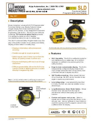
The SLD features an independently configured display with two rows of large characters that can be clearly read in the field and set to display any EGU, it is loop-powered by less than 2.3 Volts, and the Loop Maintenance Zener Diode Option allows removal from the loop for maintenance without interrupting your safety function. Additional features include RFI/EMI immunity, superior accuracy of ±0.012% of input scale, easy calibration, and superior reliability with up to 5 years between scheduled calibrations.

Recommandé
Recommandé
Contenu connexe
Plus de Arjay Automation
Plus de Arjay Automation (20)
Dernier
Dernier (20)
Functional Safety Programmable Loop Display
- 1. 178-731-00A 2017 Moore Industries-International, Inc. SLDFunctional Safety Programmable Loop Display Page 1 Description Moore Industries’ universal SLD PC-Programmable Functional Safety Loop Display features a large integral display that shows real-time process status in mA, percent, or any designated 5-character Engineering units (EGU). The SLD is part of Moore Industries’ FS Functional Safety Series products. It is certified by exida as a SIL3 capable, non-interfering device for use in a safety loop. The SLD Functional Safety Programmable Loop Dis- play is the perfect solution to accurately and reliably display process status in a safety loop: • Displays information with phenomenal accuracy • Flexible enough to mount anywhere • Select square root or linear curve from the library or quickly create a custom one • Easy-to-read display with two rows of large characters • DTM programmability allows the SLD to be custom scaled to display percent or scaled directly in engineering units All product names are registered trademarks of their respective companies. Features ■ SIL3 Capability. The SLD is certified by exida for non-interference in a safety loop. (It is not SIL3 assessed or certified to be used as part of the safety function). ■ Easy-to-read, customizable display. The SLD’s independently configured display features two rows of large characters that can be clearly read in the field and set to display any EGU. ■ 360° flexible mounting. When placed into one of our housings, the SLD can be mounted at any angle in nearly any environment. ■ Low voltage drop. Loop-powered by less than 2.3 Volts, the SLD can even be installed on bur- dened loops. ■ Loop Maintenance Zener Diode Option. Allows the SLD to be removed from the loop for maintenance without interrupting your safety function. ■ Custom and square root curves. Select a square root or linear curve from the library, or cre- ate your own. Use our software to input a table in one EGU and have the PC program convert it into a different EGU for display. Figure 1. The SLD is available complete in our BH housing; an explosion-proof enclosure that protects your display in even the harshest field environments. May 2017 The SLD installs easily on the loop, protected by an Explosion-Proof BH housing. Certifications Large, Easy-to-Read Display Large, Easy-to-Read Display 4-20mA Loop Input Arjay Automation, Inc. | 800-761-1749 www.arjaynet.com
- 2. w w w . m i i n e t . c o m • Demand Moore Reliability SLD Page 2 Functional Safety Programmable Loop Display ■ RFI/EMI immunity. The SLD is resistant to the harmful, unpredictable effects of radio frequency and electromagnetic interference. ■ Superior Accuracy. The loop-powered SLD reads any 4-20mA signal and displays the infor- mation with phenomenal accuracy of ±0.012% of input scale. ■ Easy Calibration. A single button on the front of the unit allows you to easily calibrate your loop by displaying the loop current in mA with three-deci- mal-place accuracy. ■ Superior Reliability. Up to 5 years between scheduled calibrations. Simple PC Setup The SLD Functional Safety Programmable Loop Dis- play is DTM programmable. You can program it with any FDT compliant host or program such as PACT- ware utilizing our DTM (Figure 2) and USB communi- cation cable. DTM Programmable for Fast and Accurate Con- figuration— Using the DTM, the SLD can either be custom scaled to display in a percent or scaled di- rectly into engineering units for indicating any process Figure 2. The SLD provides easy software configuration with PACTware. measurements such as pressure, temperature, level, or flow. Span, zero, input range, display range, and filtering frequency can also be easily programmed. The SLD even allows the capturing of the input range limits of the loop to provide you with the most accurate display available. FREE PACTware Configuration Software with Ver- satile Programming Options— Download PACTware software for FREE from our website which allows you to set up all display settings utilizing our DTM’s easy to use pull down menus (Figure 2). Quick Transmitter/Configuration Upload/Down- load— PACTware offers one button uploading and downloading of transmitter configuration. Toolbar for Frequently Used Commands— A conve- niently located toolbar provides quick access to often used configuration functions. Real-Time Process Readout—The process mea- surement and the communication status between the SLD and PACTware can be viewed in a one-page window. Store, E-mail, Download and Print Files—The con- figuration you’ve created may be downloaded to any number of transmitters, saved, e-mailed, or printed for record keeping.
- 3. Demand Moore Reliability • w w w . m i i n e t . c o m Page 3 SLDFunctional Safety Programmable Loop Display Monitoring Critical Functions The SLD, a member of the FS Series product line, is designed and built in compliance with IEC 61508, the leading worldwide functional safety standard. The SLD is a non-interference device and can be Figure 3. With the -LMD option the SLD can be removed from the safety loop without affecting the integrity of the SIF Specifications DISPLAY PERFORMANCE AMBIENT CONDITION WEIGHT Type: LCD; Top Row, 10mm (0.4 in) high black digits on a reflective background; Bottom Row, 6mm (0.23 in) high black digits on a reflective background Format: Top row is five alphanumeric characters plus sign and decimal point; Bottom row is five alphanu- meric characters Range: -99999 to 99999 Display Update Rate: 100msec Minimum Display Span: 1.00 Accuracy: ±0.012% of input scale. This includes the combined effects of lin- earity, hysteresis, repeatability, and adjustment resolu- tion. It does not include ambient temperature effect. Stability: Error is in % of maximum span: Resolution: 0.0028% of input scale Over-Current Protection: 100mA, maximum Display Input Overrange: 24mA Digital Input Filter: User-programmable; 50 or 60Hz Minimum Operating Current: ≥3.8mA Burden: <2.3VLP (<5.1VLP when -LMD Loop Maintenance Zener Diode option is installed and SLD is removed from the loop) Operating Range: -25°C to 85°C (-13°F to 185°F) Storage Range: -40°C to 85°C (-40°F to 185°F) Relative Humidity: 0-95%, non-condensing Ambient Temperature Effect: ±0.015% of span per °C change, maximum RFI/EMI Immunity: 20V/m@ 80-1000MHz, 1kHz AM, when tested according to IEC61000-4-3 Common Mode Rejection: 100dB@60Hz Normal Mode Rejection: 30dB@60Hz BH Housing: 1.37kg (3 lbs, 1.1 oz) HP-Style Housing: 150g (5.3 oz) SB Housing: 2.6kg (7 lbs) taken out of the loop with the –LMD option (Loop Maintenance Diode) without affecting the integrity of the SIF (Safety Instrumented Function) loop. The example shown in Figure 3 demonstrates the SLD in a SIF. It is used to display a critical tank level at eye level for plant personnel. Stability Input to Display Year(s) 1 3 5 mA 0.08 0.14 0.18 SLD with - LMD option for SIS Loops 4-20mA -LMD Terminal SIS Logic Solver Petroleum Tank with Level Sensor
- 4. Demand Moore Reliability • w w w . m i i n e t . c o m Page 4 SLDFunctional Safety Programmable Loop Display Ordering Information Accesories PACTware software is available for free on the Moore Industries web site. Visit www.miinet.com/pactware. Cables must be purchased separately. UNIT INPUT OUTPUT POWER OPTIONS HOUSING SLD Functional Safety Loop Dis- play 4-20MA Loop Input PRG Programmable via FDT host with sup- plied DTM to display a percent or any other EGU of up to 5 char- acters in length. 2.3VLP Loop Powered -LMD Loop Maintenance Zener Diode provided at input terminals allowing the SLD to be removed from the loop without in- terrupting loop continuity (Burden: increases from <2.3 to <5.1VLP when SLD is removed from the loop) -ISE: ATEX Approved Intrinsically-Safe BH2NG* (*) or (‡) Aluminum 2-Hub, Explosion-Proof en- closure with two, ½-inch NPT entry ports and a glass cover BH2TG* (*) or (‡) Aluminum 2-Hub, Explosion-Proof enclo- sure with two, ¾-inch NPT entry ports and a glass cover BH2MG* (*) or (‡) Aluminum 2-Hub, Explosion-Proof en- closure with two, M20 x 1.5 entry ports and a glass cover BH3NG* (*) or (‡) Aluminum 3-Hub, Explosion-Proof enclosure with three, ½-inch NPT entry ports and a glass cover BH3TG* (*) or (‡) Aluminum 3-Hub, Explosion-Proof en- closure with two, ¾-inch NPT side-entry ports, one ½-inch NPT bottom-entry port, and a glass cover BH3MG* (*) or (‡) Aluminum 3-Hub, Explosion-Proof enclosure with two, M20 x 1.5 side-entry ports, one ½-inch bottom-entry port, and a glass cover HP Hockey-puck housing and spring clips DN Snap-in mounting for HP case on TS-32 DIN-rail FL Mounting flanges on HP suitable for relay track or screw mounting FLD Mounting flanges on HP suitable for 3½” relay track or screw mounting SB2NG* (*) or (‡) 316 Stainless Steel 2-Hub, Explosion- Proof enclosure with two, ½-inch NPT entry ports and a glass cover SB2MG* (*) or (‡) 316 Stainless Steel 2-Hub, Explosion- Proof enclosure with two, M20 x 1.5 entry ports and a glass cover * Either A or E suffix (comes supplied with 2” pipe mount hardware) A suffix indicates ANZEx/TestSafe (Ex d) Flameproof approvals (i.e. BH2MGA) E suffix indicates ATEX (Ex d and tb) Flameproof approv- als (i.e. BH2MGE) ‡ P suffix indicates enclosure comes equipped with base plate and U-bolts for mounting on a 2-inch pipe (i.e. BH2NGP)See BH and SB Datasheets for additional information. To order, specify: Unit / Input / Output / Power / Options [Housing] Model Number Example: SLD / 4-20MA / PRG / 2.3VLP / -LMD [BH2NG] Part Number Part 804-030-26 Non-Isolated Fuse Protected USB Communication Cable (required by ATEX for products installed in Intrinsically-Safe areas) 803-040-26 Non-Isolated Serial Configuration Cable for 2-Wire Instruments
- 5. Demand Moore Reliability • w w w . m i i n e t . c o m Page 5 SLDFunctional Safety Programmable Loop Display Figure 2. Dimensions of the SLD in the BH explosion-proof enclosure. Figure 3. Dimensions of the SLD HP housing with mounting flanges. 68mm (2.68 in) GND 1/2 NPT 102mm (4.02 in) 84mm (3.31 in) 68mm (2.68 in) 64mm (2.52 in) 10mm (0.38 in) 124mm (4.88 in) 25mm (1.00 in) 102mm (4.02 in) 119mm (4.69 in) 76mm (2.99 in)57mm (2.24 in) 22mm (0.87 in) SIDE VIEW TOP VIEW SLD +IN -IN VIEW 62.78 PCT 62.78 PCTPCTPC 62mm (2.45 in) 76mm (3.00 in) 61mm (2.40 in) SLD +IN -IN VIEW 62.78 PCT 66mm (2.58 in) 64mm (2.50 in) 43mm (1.70 in) 83mm (3.25 in) 62mm (2.45 in) 18mm (0.70 in)
- 6. Specifications and information subject to change without notice. Printed in the U.S.A.Page 6 SLDFunctional Safety Programmable Loop Display Certifications SLD-HP SLD-HP in BH/SB2 Housing FM Approvals (FM Global Group): Non-Incendive Class I, Division 2, Groups A, B, C & D Suitable for use in: Class II, III, Division 2, Groups F & G Temperature Class T4 @ 85°C Ambient FM Approvals (FM Global Group): Explosion-Proof & Dust/Ignition-Proof Class I, Division 1, Groups A*, B, C & D Class II & III, Division 1, Groups E, F & G Environmental Protection: NEMA 4X & IP66 T6 @ 60°C Maximum Operating Ambient *For Group A applications, seal all conduits within 18” ATEX Directive 2014/34/EU (LCIE): Intrinsically-Safe II 1G Ex ia IIC T4 Ta = 85°C ATEX Directive 2014/34/EU (MII): Type “n” II 3G Ex nA IIC T4 Ta = 85°C CSA Group (Canadian Standards Association): Explosion-Proof Class I, Division 1, Groups A*, B, C & D Class II, III, Groups E, F & G Type 4X, IP66 Ambient Temp. Range: -20°C to +60°C; T6 *For U.S. Group A applications, seal all conduits within 18” CE Conformant: EMC Directive 2014/30/EU – EN 61326 ATEX Directive 2014/34/EU (ISSeP): Explosion-Proof/FlameProof II G Ex d IIC T6 Gb II D Ex tb IIIC Db T85°C IP66 ANZEx (TestSafe): Explosion-Proof/FlameProof Ex d IIC T6 (Tamb 60°C) The FS Functional Safety Series Safeguard your processes when you need it the most. Our line of SIL 2 and 3 capable instruments include Trip Alarms, Safety Relays, Isolators, Temperature Transmitters, Frequency Transmitters, and Indicators. Each has been built to strict IEC 61508 standards, and exida certified, ensuring safe and reliable function – particularly in environments where hazardous or emergency situations are likely to occur. Learn more at www.miinet.com/safetyseries or ask your rep for a copy of our Functional Safety Line Card.