FULL ENJOY Call Girls In Mahipalpur Delhi Contact Us 8377877756
M·system vos2t-r (ing)
1. VOS2T-R
P. / 4EM-4766 Rev.3
2-WIRE POSITION TRANSMITTER
(rotary motion type; 90-degree rotation)
MODEL VOS2T-R
INSTRUCTION MANUAL
BEFORE USE ....
Thank you for choosing M-System. Before use, please check
contents of the package you received as outlined below.
If you have any problems or questions with the product,
please contact M-System’s Sales Office or representatives.
■ PACKAGE INCLUDES:
VOS2T-R unit................................................................. (1)
Cable, approx. 1 meter long (optional)......................... (1)
Cable connector (optional)............................................ (1)
Lever assembly
Lever...................................................................... (1)
Connecting pin...................................................... (1)
Nailed nut.............................................................. (1)
Nut with washer (M5)........................................... (1)
Screws for attaching the lever (M5 x 8)....................... (1)
Plain washer (M5)......................................................... (1)
Toothed washer (M5, external teeth)............................ (1)
Toothed washer (M5, internal teeth)............................ (1)
Remark: Bracket, link and other components necessary to
attach the VOS2T-R to an actuator are to be provided by
the customer.
Link Set (model: VOLK) is available to simplify the connec-
tion.
■ MODEL NO.
Confirm Model No. marking on the product to be exactly
what you ordered.
POINTS OF CAUTION
■ CONFORMITY WITH EC DIRECTIVES
• When the unit is mounted onto a grounded metal bracket,
insert a noise filter for the output. COSEL Noise Filter
Model NAC-04-472 or equivalent is recommended.
■ GENERAL PRECAUTION
• Cut power supply to the unit before wiring to it.
■ ENVIRONMENT
• Inside building. If outside, keep away from direct sun-
light.
• Operating temperature -5 to +60°C (23 to 140°F)
• Operating humidity 30 to 90% RH
■ ACTUATOR SIDE LEVER
• When the actuator side lever is provided by the customer,
be sure that diameter of the hole threading the connecting
pin is 5 millimeters or wider. Diameter of connecting pin:
5 0
–0.03 mm
■ GASKET
• Be sure to return the gasket when you close the unit cover
after wiring or adjustments.
■ TORQUE
• For the screws attached to the cover, tightening torque is
between 1.2 and 1.6 N·m.
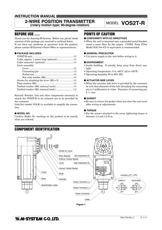
COMPONENT IDENTIFICATION
Screw for Lever
External Toothed Washer
Plain Washer
Lever
Internal Toothed Washer
Shaft
Indicator
Zero Adjustment (Z)
Span Adjustment (S)
Output Terminal (+)
Output Terminal (–)
Cable Connector
Cable
Cover
Body
Specification Label
Jumpers (JP1, JP2)
REVERSEDIRECT
JP1
JP2
R D
JP1
JP2
R D
Figure 1
2. VOS2T-R
P. / 4EM-4766 Rev.3
Figure 3
INSTALLATION
■ LINKING WITH LEVERS
• POSITIONING THE VOS2T-R SECURELY
The output accuracy of the VOS2T-R is largely affected by
its mechanical position relative to the actuator.
The VOS2T-R and the actuator respectively must positioned
so that the distance between the centers of VOS2T-R shaft
and the actuator stem (A – C) be equal to the length of the
actuator lever (B – D) as in Figure 2.
The length of actuator lever for the VOLK can be adjusted.
Refer to the “ADJUSTMENT PROCEDURE” section.
• CONNECTING THE VOS2T-R SIDE LEVER
Connect the lever to the VOS2T-R unit with a screw in-
cluded in the package, with a plain washer and a toothed
washer between them as in Figure 1. At this stage, you do
not have to fasten the screw tightly.
• CONNECTING THE VOS2T-R SIDE LEVER
TO THE ACTUATOR SIDE LEVER
(with the actuator side lever provided by the customer)
Attach the connecting pin to the VOS2T-R side lever utiliz-
ing the nailed nut and the nut as in Figure 3. The actuator
side lever should be threaded with the connecting pin but
left loose. The nail could be positioned in either side of the
lever, however it is limited to one side at the extreme end of
the lever hole.
• CONNECTING THE VOS2T-R SIDE LEVER
TO THE ACTUATOR SIDE LEVER
(with VOLK by M-System)
Connect between the levers utilizing the nailed nut as in
Figure 4.
■ LINKING WITHOUT LEVERS
Refer to Figure 5 below when the VOS2T-R is to be connect-
ed directly to an actuator without utilizing levers. Adjust
the relative positions of the actuator stem and VOS2T-R
shaft so that their center positions are in a straight line, or
otherwise use a coupling which can absorb position slides.
Note that performance of the VOS2T-R mounted in this way
is more easily affected by vibration. We recommend not to
use this method when severe vibration is observed.
ø5 –0.03
0 Lever, Actuator Side
Connecting Pin
Nailed Nut
Lever,
VOS2T-R Side
Nut with Washer
Factory
Assembled.
FIgure 2
Lever, VOS2T-R Side
Actuator Stem
Lever, Actuator Side
(M-System’s Link Set)
D
B
A
C
Bolt
Lever, Actuator Side Factory Assembled.
(Can not be
disassembled.)
Lever, VOS2T-R Side
Nut with Washer
Figure 4
VOS2T-R Body
Bracket
Actuator Stem
Actuator Body
Shaft
Coupling
Figure 5
3. VOS2T-R
P. / 4EM-4766 Rev.3
ELECTRICAL CONNECTIONS
Remove the VOS2T-R unit cover and wire to the terminals
according to Figure 6.
ADJUSTMENT PROCEDURE
First adjust the relative positions of levers and linking
mechanism.
After that, open the VOS2T-R unit cover. Set the action
direction* with jumpers (JP1, JP2 in Figure 1) and adjust
Zero (Z) and Span (S) behind it.
*Direct action: the output increases when the shaft turns
clockwise (seen from the lever side).
Reverse action: the output increases when the shaft turns
counterclockwise (seen from the lever side).
■ HOW TO ADJUST LEVERS LINKING MECHANISM
1) Electrical wires to the terminals should be done before
this adjustment. However, do not change each potenti-
ometer’s setting yet. Leave the jumper settings for ac-
tion direction as they were set at the factory (direct) at
this moment.
2) For using levers to link, loosen the VOS2T-R side nut and
washer and set the connecting pin (or bolt) position rela-
tive to other components so that the distance A – B and
C – D is the same. See Figure 2. Tighten the nut and
washer.
3) For using the VOLK in combination with the VOS2T-R
lever, adjust lever length of the VOLK so that the dis-
tance A – C and B – D is also the same. (The square
A-B-C-D must be a parallelogram or a rectangle.) Then
tighten the bolt.
If a customer provided lever is also adjustable of its
length, do the same.
4) With the actuator positioned at 50%, adjust the VOS2T-
R shaft angle with a wrench (7 mm) or by twisting the
indicator with your hand so that the VOS2T-R outputs
approx. 12mA. If you are using levers to link, tighten the
screw for lever now (torque 2.4 – 3.1 N·m). If you are not
using a lever, fix the coupling now.
5) Check the indicator and adjust its angle after loosening
its screw (M2.6) if necessary. Make sure that it is tight-
ened again after adjustment.
■ HOW TO ADJUST ZERO AND SPAN
1) If you need reverse action, change the setting now. Re-
move the cover and set the jumpers JP1 and JP2 to R po-
sition according to Figure 1. Factory set zero point may
be slided by changing the action direction. Re-adjust ac-
cording to the following.
2) First operate the actuator
slowly for full-stroke (90
degrees) and check that the
VOS2T-R outputs approxi-
mately 0 – 100% (4 – 20mA
DC) accordingly. Be sure
also that the output sig-
nal increases or decreases
without interruption.
3) With 50% input (actuator
position), check that the
output is approximately
50%. See Figure 7.
4) With 0% input, adjust the
output to 0% with Zero ad-
justment. See Figure 8.
5) Set the input to 100%. If
there is a deviation in out-
put signal, compensate half
of the deviation via the Zero
adjustment. See Figure 9.
6) With 100% input, adjust
the other half of the devia-
tion with Span adjustment
in order to get 100% output.
See Figure 10.
7) Input 0%, 50% and 100%
signals and check the out-
put according to the respec-
tive input value. If the out-
put value is shifted, repeat
the above procedure (3)
– (6).
Remark: If you set a wider output span (narrower input
span), the VOS2T-R does not output above or below the full-
scale range.
15 – 28V DC
LOAD
–
+
OUTPUT
4 – 20mA DC
Figure 6
OUTPUT %
100
500 100
INPUT %
0
Fig. 7
OUTPUT %
100
500 100
INPUT %
0
Fig. 8
deviation
OUTPUT %
100
500 100
INPUT %
0
Fig. 9
1/2 deviation
OUTPUT %
100
500 100
INPUT %
0
Fig. 10
1/2 deviation
4. VOS2T-R
P. / 4EM-4766 Rev.3
M-SYSTEM WARRANTY
1. What is covered.
M-System Co., Ltd. (“M-System”) warrants, only to the original
purchaser of new M-System products purchased directly from
M-System, or from M-System’s authorized distributors or resellers,
for its own use not for resale, that the M-System products shall be
free from defects in materials and workmanship and shall conform to
the specifications set forth in the product catalogue applicable to the
M-System products for the Warranty Period (see Paragraph 5 below
for the Warranty Period of each product).
THE ABOVE WARRANTY IS THE ONLY WARRANTY APPLICABLE
TO THE M-SYSTEM PRODUCTS AND IS IN LIEU OF ALL OTHER
WARRANTIES, EXPRESS OR IMPLIED, INCLUDING, BUT NOT
LIMITED TO, ALL IMPLIED WARRANTIES OF MERCHANTABILITY
OR OF FITNESS FOR A PARTICULAR PURPOSE.
2. What is not covered.
This warranty does not cover any M-System product which has been:
(1) modified, altered or subjected to abuse, misuse, negligence or
accident; (2) improperly installed or installed in conjunction with any
equipment for which it was not designed; or (3) damaged or de-
stroyed by disasters such as fire, flood, lightning or earthquake.
In no event shall M-System be liable for any special, incidental, con-
sequential or other damages, costs or expenses (including, but not
limited to, loss of time, loss of profits, inconvenience or loss of use of
any equipment).
3. Remedies.
If a defective product is returned to M-System in accordance with the
procedures described below, M-System will, at its sole option and
expense, either: (1) repair the defective product; (2) replace the
defective product; or (3) refund the purchase price for the defective
product paid by the purchaser. Except as otherwise provided by ap-
plicable state law, these remedies constitute the purchaser’s sole and
exclusive remedies and M-System’s sole and exclusive obligation
under this warranty.
4. Warranty Procedure.
If the purchaser discovers a failure of the M-System products to
conform to the terms of this warranty within the Warranty Period, the
purchaser must promptly (and, in any event not more than 30 days
after the discovery of such failure) notify the relevant party as de-
scribed below either by telephone or in writing at the below address
to obtain an Authorized Return (AR) number and return the defective
product to the relevant party. The designated AR number should be
marked on the outside of the return package and on all correspond-
ence related to the defective product. The purchaser shall return, at
purchaser’s expense, defective products only upon receiving an AR
number. In order to avoid processing delays, the purchaser must
include: copies of the original purchase order and sales invoice; the
purchaser’s name, address and phone number; the model and serial
numbers of the returned product; and a detailed description of the
alleged defect.
5. Warranty Period.
Signal Conditioner: 36 months from the date of purchase.
M-Rester: 12 months from the date of purchase.
Valve Actuator: 18 months from the date of shipment from
M-System or 12 months from the date of its
installation, whichever comes first.
Other Products: 36 months from the date of purchase.
M-SYSTEM CO., LTD.
5-2-55, Minamitsumori, Nishinari-ku,
Osaka 557-0063 JAPAN
Phone: (06) 6659-8201
Fax: (06) 6659-8510
E-mail: info@m-system.co.jp
MAINTENANCE
■ MECHANICAL PARTS
•Check that screws are fastened tightly and if some of them
are loosened, be sure to re-tighten them.
If you find the connecting pin loose, go through “ADJUST-
MENT PROCEDURE” again.
• Inspect visually that the connecting section of levers is
stable and smooth. Check also that the connecting pin or
lever is not worn. If it is, it must be replaced. Consult M-
System or local representative. If the abrasion advances
fairly quickly, there may be a problem in the link mecha-
nism (e.g. connecting pin position)
• If the VOS2T-R is installed outside the building or where
it is subject to water or metallic dust particles, check that
there is no crack or bruise on the gasket. If you find any,
consult M-System or local representative.
• Consult M-System or local representative also for inspec-
tion of packing (O-ring) in the moving parts.
■ ELECTRICAL PARTS
• Check first the mechanical parts as above.
• Change actuator positions and input 0%, 25%, 50%, 75%
and 100% signals. Check the output with respective input
value is within allowance indicated in the specifications.
If not, go through “ADJUSTMENT PROCEDURE” again.
LIGHTNING SURGE PROTECTION
M-System offers a series of lightning surge protectors for
protection against induced lightning surges. Please contact
M-System to choose appropriate models.