1. Robot Dreams Production Log
The Arms
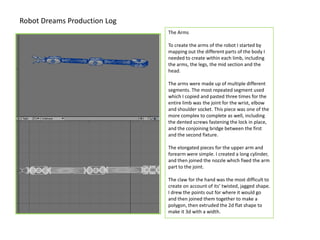
To create the arms of the robot I started by
mapping out the different parts of the body I
needed to create within each limb, including
the arms, the legs, the mid section and the
head.
The arms were made up of multiple different
segments. The most repeated segment used
which I copied and pasted three times for the
entire limb was the joint for the wrist, elbow
and shoulder socket. This piece was one of the
more complex to complete as well, including
the dented screws fastening the lock in place,
and the conjoining bridge between the first
and the second fixture.
The elongated pieces for the upper arm and
forearm were simple. I created a long cylinder,
and then joined the nozzle which fixed the arm
part to the joint.
The claw for the hand was the most difficult to
create on account of its’ twisted, jagged shape.
I drew the points out for where it would go
and then joined them together to make a
polygon, then extruded the 2d flat shape to
make it 3d with a width.
2. The Lampshade Head
To create the head of the robot first I chose the
sphere tool, once that was done I moved onto the
outset rim and cut off a section of the sphere so it
was left open, where the bulb would fit. Then I used
the extrude tool to pull the rim out and extend it
wider than the diameter of the sphere so it looked
realistic and was accurate.
Once the basic shell was done I moved onto creating
the bulb. I copied the same technique with the back
sphere and cut a section off, but selected more than
half of the shape. Once it was correct I created the
smaller filaments for the bulb by using the cylinder
tool and I merely rounded the edges and copied and
pasted them by each other. Once I had enough I
moved the entire bulb further back into the head of
the lamp shade.
3. The Feet and Ankle Joints
To create the feet for the project I first used
the flat shape tool to create the base for the
foot, then moved onto the screws implanted
in the mid sections.
Once that was done I rounded the edges of
the base foot and created the embedded
hole for the joint to fit in for the ankles.
For the ankle joints, I copied and pasted the
joints used in the elbow and rotated them so
they’d fit well in place. Once that was done I
moved onto the screws in that section and
edited that part so it fit through the piece
smoothly and looked right.
4. The mid section
For the mid section I used the same cylindrical shape I used for the
arm, and the same joint for the elbow, only I rotated it to face
vertically and join the hips to the spine.
The hips required a smaller bar and two identical flipped joints facing
horizontally and angled down to compensate for the placement of
the legs and feet.
5. The finished robot
The object was created using a range of construction techniques
from the Create, Modify, Multiply, Construct and Detail tools,
directed by aiding video tutorials, I used for assistance.