Deploying Distributed Traffic Capture Systems
•
0 j'aime•212 vues

Distributed Taps are intelligent, hardware-based network traffic capture devices designed to passively tap inline networks or connect to SPAN ports for capturing and forwarding traffic to monitoring or security tools.

Recommandé
Recommandé
Contenu connexe
Tendances
Tendances (18)
En vedette
Similaire à Deploying Distributed Traffic Capture Systems
Similaire à Deploying Distributed Traffic Capture Systems (20)
Dernier
Dernier (20)
Deploying Distributed Traffic Capture Systems
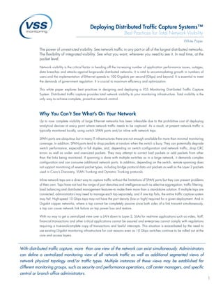
- 1. Deploying Distributed Traffic Capture Systems™ Best Practices for Total Network Visibility White Paper The power of unrestricted visibility. See network traffic in any part or all of the largest distributed networks. The flexibility of integrated visibility. See what you want, wherever you need to see it. In real time, at the packet level. Network visibility is the critical factor in heading off the increasing number of application performance issues, outages, data breaches and attacks against large-scale distributed networks. It is vital to accommodating growth in numbers of users and the implementation of Ethernet speeds to 100 Gigabits per second (Gbps) and beyond. It is essential to meet the demands of government regulation. It is crucial to maximum efficiency and optimization. This white paper explores best practices in designing and deploying a VSS Monitoring Distributed Traffic Capture System. Distributed traffic capture provides total network visibility to your monitoring infrastructure. Total visibility is the only way to achieve complete, proactive network control. Why You Can’t See What’s On Your Network Up to now complete visibility of large Ethernet networks has been infeasible due to the prohibitive cost of deploying analytical devices at every point where network traffic needs to be captured. As a result, at present network traffic is typically monitored locally, using switch SPAN ports and/or inline with network taps. SPAN ports are ubiquitous but in many IT infrastructures there are not enough available for more than minimal monitoring coverage. In addition, SPAN ports tend to drop packets at random when the switch is busy. They can potentially degrade switch performance, especially in full duplex, and, depending on switch configuration and network traffic, drop CRC errors as well as under- and oversized packets. They may attempt to correct bad packets or add packets from other than the links being monitored. If spanning is done with multiple switches as in a large network, it demands complex configuration and can consume additional network ports. In addition, depending on the switch, remote spanning does not support monitoring of several packet types, including bridge protocol data unit packets as well as the Layer 2 packets used in Cisco’s Discovery, VLAN Trunking and Dynamic Trunking protocols. Inline network taps are a direct way to capture traffic without the limitations of SPAN ports but they can present problems of their own. Taps have not had the range of port densities and intelligence–such as selective aggregation, traffic filtering, load balancing and distributed management features–to make them more than a standalone solution. If multiple taps are connected, administrators may need to manage each tap separately, and if one tap fails, the entire traffic capture system may fail. High-speed 10 Gbps taps may not have the port density (low or high) required for a given deployment. And in Gigabit copper networks, where a tap cannot be completely passive since both sides of a link transmit simultaneously, a tap can cause network link failure on tap power loss and restore. With no way to get a centralized view over a LAN down to Layer 2, SLAs for real-time applications such as video, VoIP, financial transactions and other critical applications cannot be assured and enterprises cannot comply with regulations requiring a true-and-complete copy of transactions and lawful intercepts. This situation is exacerbated by the need to use existing Gigabit monitoring infrastructure for cost reasons even as 10 Gbps switches continue to be rolled out at the core and access layers. With distributed traffic capture, more than one view of the network can exist simultaneously. Administrators can define a centralized monitoring view of all network traffic as well as additional segmented views of network physical topology and/or traffic types. Multiple instances of these views may be established for different monitoring groups, such as security and performance operations, call center managers, and specific central or branch office administrators. 1
- 2. Virtual Traffic Capture A Distributed Traffic Capture System comprises intelligent traffic capture devices deployed anywhere they need to be, architected between network infrastructure and the analytical equipment as one virtual system. In this way traffic capture closely meshes with the network’s topology. The Distributed Traffic Capture System collects a copy of traffic at any point and sends it in real time to centralized monitoring tools. Monitoring Systems VSS Distributed Access Platform Communications Infrastructure Because it functions as one system, distributed traffic capture offers network monitoring, for the first time, fault tolerance, ultra low latency, infinite flexibility and full optimization. A Distributed Traffic Capture System not only adapts as rapidly as conditions require but also delivers multiple views of the network simultaneously, so that each monitoring group can see the view appropriate to its function. 2
- 3. How to Deploy Distributed The additional capabilities of vStack+’s redundant mesh topology introduces a few choices that the traffic capture Traffic Capture architect will need to make. First is to specify the desired level The best deployment of a Distributed Traffic Capture System of redundancy. Triple redundancy is adequate in all but the is one designed to exploit its core capabilities: flexibility, most critical installations. Second is to design contingency redundancy, monitoring optimization. plans should the traffic capture system default to slower speeds and increased number of hops in the event that multiple high- Flexibility speed links between traffic capture devices fail. One of the A Distributed Traffic Capture System collapses the hierarchical most important elements in this is to set alerts to be generated schema of traditional network monitoring architecture by by a change in link status, and to have these alerts sent to virtualizing traffic capture. As a result more than one view of IT personnel, as well as, if desired, to third-party monitoring the network can exist simultaneously. This allows administrators companies via multiple methods: pager, text message, and to define a centralized monitoring view of all network traffic email. as well as additional segmented views of network physical topology and/or traffic types. Multiple instances of these Monitoring Optimization views may be established for one or more monitoring groups, By providing real time granular control of the traffic capture such as security and performance operations, call center process a Distributed Traffic Capture System can significantly managers, specific central or branch office administrators, enhance the ROI of monitoring infrastructure and the people etc. As conditions require, these parameters may be rapidly who administer it. reconfigured. The traffic capture architect should use the system’s data Before implementing a traffic capture system, a network grooming capabilities–especially selective aggregation, traffic capture architect should think about which views are filtering, and load balancing–to maximize the traffic reaching the most important given the speeds, nature of traffic and its each analytical device, ensuring that each device is fully location in the network’s core, distribution, access and/or subscribed to only its traffic of interest. Examples of these gateway layers, the analytical equipment on hand and to be decisions include splitting voice and data signaling traffic to implemented, the level of traffic-capture redundancy required, respective analyzers, sending the same traffic to analyzers in and how the traffic capture and monitoring systems will be different regions, and using multiple 1-Gigabit analyzers to managed–e.g., permission levels for management views of monitor a 10 Gbps stream. device configurations and port assignments–and the personnel available for monitoring. Designing a Distributed Redundancy A Distributed Traffic Capture System’s mesh topology is fault- Traffic Capture System tolerant. VSS Monitoring’s vStack+™ technology auto discovers The design of a Distributed Traffic Capture System is oriented link failures and re-routes the copied traffic automatically, to the requirements of the monitoring devices. Four types of using the highest speed links and lowest number of hops. commonly used passive monitoring equipment are intrusion This capability eliminates the pitfalls associated with similar detection systems, performance monitors, service assurance topologies in network IP routing, such as convergence time tools and data recording devices. Each of these devices may and route flap as well as the need to manage routing tables. need to see only certain slices of traffic, such as HTTP, voice, video, signaling, or VLAN tagged packets, and from only The redundant mesh topology also offers a number of selected network segments or the entire network. advantages over traditional connectivity approaches for traffic capture devices such as daisy chaining or stacking. Each of Design also varies by need. Key design criteria for traffic these introduces a single point of failure (if one traffic capture capture are similar to those of an IP network. They include: device fails the entire traffic capture system fails). In addition, availability, efficiency, lower latency, optimization, security, their serial connectivity increases latency, requires that each stability and throughput. Each organization should decide its traffic capture device be configured separately, as if it were own prioritization of these criteria depending on the services standalone, and limits their management to a single campus. delivered and to whom they are delivered. 3
- 4. In general, design criteria that traffic capture architects should take into account include: ƒ The number of networks being monitored. ƒ Whether their media are copper, fiber or mixed. ƒ The location and number of capture points, whether SPAN ports or inline. ƒ The speed for each link associated with a capture point. ƒ The type and volume of traffic to be monitored. ƒ The performance capability/bandwidth of the analytical equipment and its location. ƒ Available rack space. ƒ The topologies of traffic capture depending on desired visibility and redundancy: full mesh, star and/or star-mesh hybrid. The most efficient design process for a Distributed Traffic Capture System usually follows these steps: 1) Determine the traffic your monitoring tools must see. 2) Identify the traffic capture points. 3) Map the capture points to the best combinations of port densities, speeds and grooming capabilities of the traffic capture device connected to that capture point. Do this for each monitoring view desired. 4) For each view, at the traffic capture distribution layer configure the monitor output ports to send traffic customized for each monitoring device. An additional factor to take into account is how the traffic capture device handles Gigabit failover on copper media should the device lose power. A traffic capture architect should ensure that the device will failover quickly enough, typically less than 100 milliseconds, so as not to cause link loss. Gigabit traffic capture devices may cause a momentary link failure when power is lost or restored. This can disrupt time-sensitive traffic and cause unnecessary spanning tree and routing changes, with additional delays due to network reconfiguration. VSS Monitoring’s vAssure™ reduces normal Gigabit fail-over time to ≤ 100ms (typically 30-60ms), helping ensure that packet-sensitive applications running on copper media, such as VoIP and Video on Demand, continue to function uninterrupted and at specified quality-of-service levels. VSS traffic capture devices are the fastest in link switch-over and the only ones that do not cause link loss. The key to effective monitoring is being able to scale a growing number of analytics systems across a growing number of capture points. A Distributed Traffic Capture System offers the flexibility, redundancy and monitoring optimization necessary to cost-effectively achieve unrestricted visibility. USA Japan China (Corporate HQ) + 81 422 26-8831 phone + 86 10 6563- 7771 phone + 1 650 697 8770 phone + 81 422 26-8832 fax + 86 10 6563- 7775 fax + 1 650 697 8779 fax T’s Loft 3F, 1-1-9, C519, 5 Floor, 1850 Gateway Drive, Suite 500 Nishikubo, Musashino, CBD International Tower San Mateo, CA 94404 Tokyo, 180-0013 16 Yong’An Dong Li, USA Japan Beijing, China 100022 www.vssmonitoring.com www.vssmonitoring.co.jp www.vssmonitoring.com.cn VSS Monitoring, Inc. is the world’s leading innovator of Distributed Traffic Capture Systems and network taps, focused on meeting the rapidly evolving requirements of security and performance conscious network professionals. Distributed Traffic Capture Systems herald a new architecture of network monitoring, one which fundamentally improves its capability and price-performance. VSS, Distributed Traffic Capture System, vAssure, vStack+, and LinkSafe are trademarks or registered trademarks of VSS Monitoring, Inc. in the United States and other countries. Any other trademarks contained herein are the property of their respective owners. © Copyright 2003 – 2011. VSS Monitoring Inc. All rights reserved. 1200 -20110127.1703r-003