SlideShare une entreprise Scribd logo
1  sur  36
4/2/2012


                                  Assignment - 2


202CDE               EMBD. MICROPROCESSORS GROUP PROJECT


                                          Group NTP
                  Divay Khatri                          –              4073084
                  Aleksandr Fedunov                     –              3238989
                  Cagdas Degirmenci                     –              3052983
                  Salem Bazeedan                        –              3522590

To design a robotic vehicle using a PIC18F4520 microcontroller board, stepper motors, Darlington
Driver, photo reflective optical sensor, light dependent resistor and switches. The task is to design a
Light Sensing Robot using all the above stuff and to make it search for light within an enclosed area
with the boundary as the black tape and stop at a distance of 15cm from the light source and two
switches which help to re-negotiates the path once collided with the obstacle.
INDEX
                     Contents                                        Page No.

 Who did what?                                                                                2

 Introduction                                                                          3–5

 Design Process                - Hardware Design                                       6–8
                               - Software Design                                      9 – 15

 Implementation                                                                     16 – 19
                       - Code                                                       20 – 25
                       - PCB                                                        26 – 30

 Components used                                                                          31

 Test Methodology                                                                   32 – 34

 Conclusion                                                                               35

 References                                                                               36

                                   Who did what?
Divay Khatri

The whole software thing + helped with the hardware part + helped with PCB
design + report from design process till the end

Aleksandr Fedunov

Helped with the hardware part + Introduction and conclusion for the report

Cagdas Degirmenci

Helped with the hardware part + helped with PCB design

Salem Bazeedan

Helped with the hardware part

   And in the start of the assignment we discussed the logic about how to do this together.


                                                                                   2|P a ge
Introduction:
What is a robotic vehicle?

The field of robotics encompasses a broad spectrum of technologies in which computational
intelligence is embedded in physical machines, creating systems with capabilities far
exceeding the core components alone. Such robotic systems are then able to carry out tasks
that are unachievable by conventional machines, or even by humans working with
conventional tools. The ability of a machine to move by itself, that is, “autonomously,” is
one such capability that opens up an enormous range of applications that are uniquely
suited to robotic systems.

To be useful in real world, robots need to move safely in unstructured environments and achieve
their given goals despite unexpected changes in their surroundings. The environments of real robots
are rarely predictable or perfectly unknown so it does not make sense to make precise plans before
moving. This report will describe how we designed and built a light sensing robot.

The task is to build a light sensing robot using two LDR’s to sense the light and accordingly
move the wheels, one opto sensor to remain within the boundary, two switches to change
the direction of the robot when gets collided with an obstacle, all this on a PIC18F4520
microcontroller board, and a Darlington driver to control the locomotion aspect of the
vehicle.

Our first step was to understand how the robot should work and what things it needs to
perform.

       If the sensors (LDR) sense bright light, i.e. approximately a distance of 15cm away
       from the robot, then the robot must stop.
       If the sensors sense extra light than the normal light, then the sensor which is having
       some extra light, the vehicle should move in that direction.
       If both the sensors sense the same amount of extra light then the vehicle should
       move in the forward direction.
       If the opto reflective sensors value is 0 then do all of the above steps else if it is 1
       that means the robot is over the boundary, the black line. So it should move
       backwards and then turn to a direction and then again should start searching for
       extra light.
       If the switches gets pressed, that means the robot has collided with something (an
       obstacle) and it needs to change its way. When a switch gets pressed, the interrupt
       comes in.


Let’s get into the detail of these steps,

The robot should move within an enclosed black taped area which robot must sense via
photo reflective optical sensor. The main task is that robot should search for a light source
by using LDR’s (Light Dependant Resistors) and when it collides with an obstacle with the

                                                                                        3|P a ge
lever switchers(bumpers) it should re-negotiate its path towards the light source. After
robot reaches the light source it should stop at a small distance from it.

We were given four weeks to complete this project for from both hardware and software
aspects. This was not that tough task as we have successfully completed our first
assignment – Line following robot few months ago. Some things were similar, some piece of
the code was similar and we had to attach the sensors to the same vehicle platform.

But there was a difference this time, logically if a vehicle has to move then one wheel should
rotate in the clockwise direction and the other in the anti-clockwise direction to make the
vehicle move but in actual both the wheel should move in the same direction (the forward
direction to move forward and vice-versa).

The thing which was changed for us was the polarity of the stepper motors we were using
where we had to set the locomotion aspect of the wheels with both motors moving in the
clockwise direction.

Below we will discuss about the general idea as on the set-up with the stepper motors.

Our objective for the first week was to find a voltage values for LDR’s (how it reflects the
light) and resistor values for the LDR’s, Optical sensor and Lever switchers. To calculate
values of the resistors we used data sheets of each component (sensor). Calculations are
given in the main body, after the calculations we started attaching the sensors and the
switches one by one to the breadboard and with the development board, the LDR’s using
analogue to digital channel 0 and channel 1 to PORTA bit 0 and 1 assigned the decimal
values to the code where it should follow the light source and stop at some distance from it
(using 8 bits) and then tested it along with a stepper motors. The confirmation was that the
LDR’s reacted well to the light and the stepper motors moved accordingly. The first week
was over.

On the second week our objective was to achieve the task with the interrupts by using lever
switchers. The resistor values for this were found in the schematic given. We already knew
from the lectures that we must use 2 interrupts, one low priority and the other high priority.
The high interrupt have a privilege mode. For example if a low interrupt is currently doing
the instruction, a high interrupt can easily interrupt the low interrupt but the vice-versa is
not true. We completed this objective for the week and made the interrupts work. When
one of the bumpers is pressed then the stepper motors do some steps, it moves in the
backward direction, turn to either left or right and then move forward searching the light.

Attaching the opto sensor was the last step so for the third week we arranged everything
together including the opto sensor and compiled the code. Everything worked fine but we
couldn’t stop the wheels at 15cm distance from the light source.

After we saw it working, we recorded the video of the set-up which can be found below.


                                                                                   4|P a ge
Then the fourth week we started connecting components on the robotic vehicle and make it
   move, the objective for the last week of the project. The video below can demonstrate how
   it works on the vehicle and can prove that the entire task was done successfully.


   What we were done so far is:

       Stepper motors works with the LDR’s
       Optical reflective sensor can avoid the black line
       The lever switchers works perfectly fine as the interrupts and can perform the tasks
        to re-negotiate the obstacle
       The LDR’s make the stepper motors move to follow the light and stops them at a
        given range

   The idea is to make the robotic vehicle within an enclosed black taped area and follow the
   light source. When it reaches the obstacle it must perform steps to re-negotiate it/avoid it
   and then again should follow the light source. If it reaches the black tape or the boundary it
   should change the direction.


We made two videos showing the working of the light sensing robot:
    Set-up of the hardware (an in working with the individual parts)
              http://www.youtube.com/watch?v=6825V6opX7Q

    The moving robotic vehicle
            http://www.youtube.com/watch?v=qKiPZ4BL_vA


                                                                                      5|P a ge
Design Process:
Below is the diagram that shows the set-up of the hardware, with all the sensors, their
respective resistors, the switches, PIC development board and the stepper motors. Or we
can say the circuit diagram.


                                                                             6|P a ge
To understand more about this let us have a look at the UML diagram for the hardware
design.

                UML activity diagram for Hardware Design


                                                                          7|P a ge
This is the general idea from hardware point of view about what is happening. Now let us
have a look at how to make the robot move in forward and backward direction. From
previous classes we figured out that for a full step sequence in a clockwise direction, the
values for the steps should be:


                             STEP 1           0x09
                             STEP 2           0x05
                             STEP 3           0x06
                             STEP 4           0x0A

And thus for the full step sequence in an anticlockwise direction, the values for the steps
should be reversed:
                             STEP 1           0x0A
                             STEP 2           0x06
                             STEP 3           0x05
                             STEP 4           0x09
This sequence applies only for one stepper motor but if we have to make two stepper
motors move simultaneously then the stepping sequence will be:

   1. Make both the motors move in clockwise direction:

                             STEP 1           0x99
                             STEP 2           0x55
                             STEP 3           0x66
                             STEP 4           0xAA

   2. Make both the motors move in anti-clockwise direction:

                             STEP 1           0xAA
                             STEP 2           0x66
                             STEP 3           0x55
                             STEP 4           0x99


   3. Make one motor in anti-clockwise direction and the other in clockwise direction


                             STEP 1           0xA9
                             STEP 2           0x65
                             STEP 3           0x56
                             STEP 4           0x9A


                                                                                 8|P a ge
This was the general idea of how to make the motors move. In our Project we have
   connected 4-7 bits of PORTD with Motor 2 and 0-3 bits of PORTD with Motor 1. Now let us
   have a look at the software design.

   Software design:
   After making the connections according to the circuit as shown above, MPLAB was launched
   and a new project was created so as to program the PIC18f4520 through the ICD 3. We
   started programming the PIC in C language.

   1.
          a. First we configured the operational parameters of the PIC by setting OSC mode
             to HS high speed clock.
          b. Then the watchdog timer was set to OFF.
          c. Low Voltage Programming was also set to OFF.
          d. And a state to compile without extra Debug compile code was set.

   2. Header files (Include files) were included in the program
         a. #include <p18f4520.h>               -       device used is the PICF4520
         b. #include <delays.h>                         -        to include the delay routines
         c. #include <adc.h>                    -       to include the files used in the analogue
            to
                                                        digital conversion
         d. #include <stdio.h>                  -       this describes the interface to the library
                                                        which contains basic I/O functions
         e. #include <portb.h>                          -        to set port b for interrupts and
            use                                                                                 the
                                                        default registers defined in it

   3. The stepping sequence was figured out in the previous classes and according to that
      stepping sequence where the stepper motors did a clockwise and anti-clockwise turn;
      the steps were assigned hexadecimal values.


          We know that

                                 0x00                         For the 0-3 bits of the PORT

Used to represent hexadecimal
values
                                               For the 4-7 bits of the PORT


                                                                                        9|P a ge
Thus to make a robotic vehicle move in the forward direction, we need to make one motor
move in anti-clockwise direction (i.e. Motor 1) and the other motor in clockwise direction
(i.e. Motor 2) and we have to make changes in the directions of both the motors according
to the response from the photo reflective optical sensors, light dependent resistors and the
switches.

But the robotic vehicle we were working on was having a different setting in the motor and
thus we had to set both the wheel in clockwise direction in order to make the robot run.

Practically, both the motors should move in the forward direction but logically both in the
opposite directions but with our robotic vehicle the case was different and thus the stepping
sequence in the end was changed.

We have assigned appropriate hexadecimal values to the steps and they are: (you will see in
comparison)

When done on stepper motors (left side) and when done on the robotic vehicle (right side)

      STEP 1              0xA9                          STEP 1              0x99
      STEP 2              0x65                          STEP 2              0x55
      STEP 3              0x56                          STEP 3              0x66
      STEP 4              0x9A                          STEP 4              0xAA
      STEP 5              0xA0                          STEP 5              0x90
      STEP 6              0x60                          STEP 6              0x50
      STEP 7              0x50                          STEP 7              0x60
      STEP 8              0x90                          STEP 8              0xA0
      STEP 9              0x09                          STEP 9              0x09
      STEP 10             0x05                          STEP 10             0x05
      STEP 11             0x06                          STEP 11             0x06
      STEP 12             0x0A                          STEP 12             0x0A
      STEP 13             0x9A                          STEP 13             0xAA
      STEP 14             0x56                          STEP 14             0x66
      STEP 15             0x65                          STEP 15             0x55
      STEP 16             0xA9                          STEP 16             0x99


4. Then we declared the interrupts according to the low and high priority and used the
   GOTO command to go to their respective definitions.

5. Then we initialized all the bits (0-7) of PORTD for outputs and all 7th bit of Port C for the
   input from opto sensor, 0 and 1st port bit of Port B for interrupts and 0 and 1st bit of Port


                                                                                    10 | P a g e
A for inputs from both LDR’s. Also included a while loop (with while = 1) such that the
   code can run forever.

6. Then we included the code for the Analogue to Digital conversion twice, once for
   channel 0 and next for channel 1 and transferred that converted digital value to the
   respective LDR.

7. Now we compared the value of LED1, if 0 then proceed normally, else if 1 then go to the
   else part.

8. If LED1 =0, starts the basic logic to control the locomotion aspect of the vehicle which
   uses the ADC converted value to steer the robot. There are 5 conditions which can be
   included

       a. If LDR1 > LDR2
          Then stop left stepper motor and move the right stepper motor in forward
          direction in order to move the robot to the left.
       b. If LDR2 > LDR1
          Then stop right stepper motor and move the left stepper motor in forward
          direction in order to move the robot to the left.
       c. If LDR1 == LDR2
          This situation occurs rarely; in this both the wheels move in the forward
          direction.
       d. If LDR1 and LDR2 are less than 245 (the voltage value of LDR at a distance of
          approx 15cm) then the robot should stop
       e. Another case can be if LDR1 and LDR2 both values are falling below a certain
          range which means there is no extra light and in that case the robot can rotate
          left or right by remaining at the same position. But we have not included this in
          the code as it was simply to follow the light source and stop


9. If LED1 = 1, starts the else part which is just a condition to move the robot backwards
   and turn to a direction. This case happens when the robot is over the black line and thus
   according to the code it can’t cross the black tape which acts as the boundary.

10. Then there are two switches in the hardware design which are bumpers, when the robot
    collides the switch gets pressed and acts as an interrupt and accordingly the interrupt
    function works. If switch 1 gets activated then the robot moves backwards, turn to right
    and move forward for some steps and then again starts following the light as it gets back
    into the main program. Similar happens when switch 2 gets activated.


                                                                                 11 | P a g e
For the opto sensors and the light dependent resistors we need to find their resistor values
using the data sheets from the manufacture of those sensors thus the calculations are given
below:

For opto sensor:


     RD =                                                           RL =

          RD =                                                             RL =
For LDR’s:     RD = 82.5 Ω                                                 RL = 25 GΩ

                                                                                12 | P a g e
Voltage Out – 320 V (maximum)
                                        Current – 75 mA (maximum)

                                                     1000 LUX              - 400Ω
                                                     10 LUX                - 9 kΩ

                                                      VOUT =

                                                                          =

                                                                      =

                                                                  Rx =


This was a general calculation.

But the output never goes to complete 5V or to complete 0V; therefore using Vout as 4.3
volts and 0.7 volts the values of Rx comes out to be 2.457 KΩ and 1.465 KΩ.

But as advised we had to use the values that we used during the normal exercises.


The above software design and interrupt routine steps are presented through
the UML activity diagrams, please see below.


                                                                                13 | P a g e
UML activity diagram for Software Design


                                           14 | P a g e
UML activity diagram for the Interrupt sequence


                                                  15 | P a g e
Implementation of the design
Implementation of the design wasn’t challenging as we have already completed assignment
1 and the exercises we have carried out since the start of the module. As we knew about the
previous components, the opto sensors, the LDRs there was just the interrupts which was
new to us. But that was also done easily.

Setting up the connection and understanding how the circuit worked was quiet easy. When
we came across a problem; such as unresponsive equipment, it did not take us long to figure
out what the problem was because we were familiar with the equipment. Having these
advantages we quickly set-up the circuit. We have explained below the circuit step by step
and explained further the reason of these connections.

The schematic was given to us and we had to arrange the circuit in the same manner.


                                                                                16 | P a g e
This is the set-up of the hardware with individual components.


About the hardware set up:
   a) Firstly we connected the PIC I/O board and the PIC development board with a 10-pin
      ribbon cable. This connection was made from the PIC I/O board to Port D on the
      development board. Using this connection we were able to cross-over 8-bit of
      information.

   b) Then with an 8-way connected wire, we have connected I/O board with the
      microcontroller’s input.

   c) The output of the microcontroller is then connected to the stepper motors. 0-3 bits
      to one of the stepper motor and 4-7 bits into the other stepper motor.

   d) After completing the main connections, we moved on to power supply connections
      where 5V were connected to most of the boards and 12V was only connected to the
      stepper motors.

   e) We then connected the optical sensor, the LDR, and the switches with their
      respective resistors to the bread board which was already powered by 5V.


                                                                              17 | P a g e
f) We then connected the output of these sensors to the respective ports in the PIC
      microcontroller board.

   g) Finally with an RJ11 cable, we connected the PIC board to MBLAB ICD3 (programmer
      and debugger) device.

   h) Then connected the 4 white LED light source with +5v and GND and started checking
      whether the hardware responds accordingly or not.


While connecting the circuit we did encounter simple problems. They are seen simple
because we easily found solutions to them. For example when we were planning on how to
stop the robotic vehicle when closer to the light source, we come across logical difficulties.
We were first trying to use a 10 bit adc channel and the values with that were coming in the
range of greater than 800 for the voltage output of LDR but we resolved this by using a 8 bit
which returned a voltage output of 245 (at a distance we needed).

The table below shows different voltage output values at different sensitivities of the light.


                   Light Sensitivity         LDR1             LDR2
                   Normal Light              224 volts        221 volts
                   Bright Light              246 volts        245 volts
                   Medium bright Light       244 volts        244 volts


The ‘brain` of the circuit is the PIC18F4520 and it has been programmed with a C language
code which we have written and it works according to our preferences.

Firstly we have connected the Darlington board with the Port D on the PIC. The port D on
the PIC is an output interface and we use this output to control the stepper motors. The pins
0-3 are programmed to use the LDR1 corresponding to motor 1 and the pins 4-7 are
programmed to use the LDR2 corresponding to motor2. The pins 9 and 10 are for ground
connections. A 5V power supply was connected to the PIC Board. The other end of the
Darlington driver is used to connect the Stepping motors on the robotic vehicle. The wires
coming out windings of the stepping motors had to be individually connected on the
Darlington board. The wires have to be connected in the pattern of White, White, Blue,
Blue, then White, White and Blue, Blue. The Darlington driver was powered with 12Volts.

The stepping motors surely needed power to run so we also connected the two with 12Volts
through +Vmotor connection. The next connection we made was connecting the two LDR’s,
the two switches and one optical reflective sensor to the PIC board. We configured our
program in such way that each sensor was assigned to a stepping motor. In simplicity each
sensor acted as an eye for the motor it was assigned to. The connection of the hardware
components is still the same as defined in the design section.


                                                                                    18 | P a g e
LDR                                                                      Opto sensor


The Opto Sensor output goes to Port C bit 7 acts as the input where it detects a black line;
LDR1 and LDR2 through an ADC bit 0 and 1 of Port A and the Lever Switches to Port B 0 and
1. These inputs are configured in the program so the motors act on these values.


Then we programmed the PIC microcontroller through ICD3. The
code is given below:


                                                                                19 | P a g e
The program code in ‘C’ for the Light Sensing Robot
/* Group Ntp - Light Sensing Robot
Divay Khatri - 4073084
Aleksandr Fedunov - 3238989
Cagdas Degirmenci - 3052983
Salem Bazeedan - 3522590
*/
// configure operational parameters of the PIC
#pragma config OSC = HS
#pragma config WDT = OFF
#pragma config MCLRE = ON
#pragma config DEBUG = OFF
#pragma config LVP = OFF

// header files
#include<p18f4520.h>
#include<delays.h>
#include<portb.h>
#include<stdio.h>
#include<adc.h>

#define LED1 PORTCbits.RC7
// define PORTC bit 7 for output from opto sensor

// Stepping Sequence - according to the robotic vehicle
// move forward
unsigned char STEP1 = 0x99;
unsigned char STEP2 = 0x55;
unsigned char STEP3 = 0x66;
unsigned char STEP4 = 0xAA;

// stop left and move   right
unsigned char STEP5 =   0x90;
unsigned char STEP6 =   0x50;
unsigned char STEP7 =   0x60;
unsigned char STEP8 =   0xA0;

// stop right   and move   left
unsigned char   STEP9 =    0x09;
unsigned char   STEP10 =   0x05;
unsigned char   STEP11 =   0x06;
unsigned char   STEP12 =   0x0A;

// stop the motors
unsigned char STEP13 = 0x00;

// LDR1 = left and LDR2 = right
void high_isr (void);
void low_isr (void);

void INT0_ISR(void); //Prototype for the goto that follows
void INT1_ISR(void);


                                                             20 | P a g e
#pragma code high_interrupt = 0x08 //High Interrupt vector @ 0x08

void high_interrupt (void) // At loc 0x08 we place the assembler instruction
GOTO
{
      _asm // This is the assembly code at vector location
      GOTO high_isr
            _endasm
}
#pragma code

#pragma interrupt high_isr
void high_isr (void)
{
      if (INTCONbits.INT0IF == 1)
// Was interrupt caused by INT0 ?

           INT0_ISR (); // Yes , execute INT0 program
}

#pragma code low_interrupt = 0x18

void low_interrupt (void) // At loc 0x08 we place the assembler instruction
GOTO
{
      _asm // This is the assembly code at vector location
      GOTO low_isr
            _endasm
}

#pragma code // used to allow linker to locate remaining code
#pragma interruptlow low_isr
void low_isr (void)
{
      if (INTCON3bits.INT1IF == 1)
            INT1_ISR ();
}
int LDR1 = 0;
int LDR2 = 0;
int i;

void main (void)
{
      ADCON1 = 0xFF;
      TRISD = 0x00;
      LATD = 0x00;
      TRISA = 0xFF;
      TRISC = 0xFF;

     // setting the interrupts
     INTCONbits.INT0IE = 1; //Enable INT0 interrupts
     INTCONbits.INT0IF = 0; // Clear INT0 Interrupt flag
     INTCON3bits.INT1IE = 1; //Enable INT0 interrupts
     INTCON3bits.INT1IF = 0; // Clear INT0 Interrupt flag
     INTCON3bits.INT1IP = 0;

     RCONbits.IPEN = 1;
     INTCONbits.GIE = 1; // Enable global interrupts
     INTCONbits.GIEL = 1;
     INTCONbits.GIEH = 1;                                           21 | P a g e
while(1)
       {
             OpenADC(ADC_FOSC_32 & ADC_LEFT_JUST & ADC_0_TAD,ADC_CH0 & ADC_INT_OFF &
ADC_VREFPLUS_VDD & ADC_VREFMINUS_VSS, 0b1011);

             SetChanADC(ADC_CH0);         /* Selects the pin used as i/p to the */
             Delay10TCYx(20);             /* delay for 200 instruction cycles */
             ConvertADC( );               /* start A/D conversion */

             while(BusyADC( ));           /* wait for completion   */

             LDR1 = ADRESH;

             OpenADC(ADC_FOSC_32 & ADC_LEFT_JUST & ADC_0_TAD,ADC_CH1 & ADC_INT_OFF &
ADC_VREFPLUS_VDD & ADC_VREFMINUS_VSS, 0b1011);

             SetChanADC(ADC_CH1);         /* Selects the pin used as i/p to the */
             Delay10TCYx(20);             /* delay for 200 instruction cycles */
             ConvertADC( );               /* start A/D conversion */

             while(BusyADC( ));           /* wait for completion   */

             LDR2 = ADRESH;

             if(LED1 == 0)
             {

//LDR's controlling stepper motors
// to check if ldr greater than ambient light and less than 15cm light

                   if(LDR1 <= 245 && LDR2 <=245)
                   {
                          if(LDR1 > LDR2)
                          {
                                 LATD = STEP5;
                                 Delay10KTCYx(12);

                                   LATD = STEP6;
                                   Delay10KTCYx(12);

                                   LATD = STEP7;
                                   Delay10KTCYx(12);

                                   LATD = STEP8;
                                   Delay10KTCYx(12);
                             }

                             else if(LDR2 > LDR1)
                             {
                                    LATD = STEP9;
                                    Delay10KTCYx(12);

                                   LATD = STEP10;
                                   Delay10KTCYx(12);

                                   LATD = STEP11;
                                   Delay10KTCYx(12);

                                   LATD = STEP12;
                                   Delay10KTCYx(12);
                             }


                                                                           22 | P a g e
else if(LDR2 == LDR1)
                        {
                             LATD = STEP1;
                             Delay10KTCYx(12);

                             LATD = STEP2;
                             Delay10KTCYx(12);

                             LATD = STEP3;
                             Delay10KTCYx(12);

                             LATD = STEP4;
                             Delay10KTCYx(12);
                        }
                 }
                 else

                 {
                        LATD = STEP13;
                        Delay10KTCYx(12);
                 }
           }
           else if(LED1 == 1)
           {
                 for(i=0;i<14;i++)
                 {
                       LATD = STEP4;
                       Delay10KTCYx(12);

                        LATD = STEP3;
                        Delay10KTCYx(12);

                        LATD = STEP2;
                        Delay10KTCYx(12);

                        LATD = STEP1;
                        Delay10KTCYx(12);

                 }
                 for(i=0;i<14;i++)
                 {
                       LATD = STEP5;
                       Delay10KTCYx(12);

                        LATD = STEP6;
                        Delay10KTCYx(12);

                        LATD = STEP7;
                        Delay10KTCYx(12);

                        LATD = STEP8;
                        Delay10KTCYx(12);
                 }
           }
     }
}
                                                 23 | P a g e
// Interrupt routine INT0_ISR

void INT0_ISR (void) // This is the interrupt service routine
{
      for(i=0;i<7;i++)
      {
            //    reverse; (for 3 times)
            LATD = STEP4;
            Delay10KTCYx(12);

           LATD = STEP3;
           Delay10KTCYx(12);

           LATD = STEP2;
           Delay10KTCYx(12);

           LATD = STEP1;
           Delay10KTCYx(12);
     }

     for(i=0;i<5;i++)
     {
           //    stop right wheel and move left wheel (2 times)
           LATD = STEP9;
           Delay10KTCYx(12);

           LATD = STEP10;
           Delay10KTCYx(12);

           LATD = STEP11;
           Delay10KTCYx(12);

           LATD = STEP12;
           Delay10KTCYx(12);
     }

     for(i=0;i<4;i++)
     {
           //    go forward; (1 time)
           LATD = STEP1;
           Delay10KTCYx(12);

           LATD = STEP2;
           Delay10KTCYx(12);

           LATD = STEP3;
           Delay10KTCYx(12);

           LATD = STEP4;
           Delay10KTCYx(12);
     }

INTCONbits.INT0IF = 0; // Clear INT0 flag before returning to main program
INTCON3bits.INT1IF = 0; // Clear INT0 flag before returning to main program
}


                                                                  24 | P a g e
void INT1_ISR (void) // This is the interrupt service routine
{
      for(i=0;i<7;i++)
      {
            //    reverse; (for 3 times)
            LATD = STEP4;
            Delay10KTCYx(12);

           LATD = STEP3;
           Delay10KTCYx(12);

           LATD = STEP2;
           Delay10KTCYx(12);

           LATD = STEP1;
           Delay10KTCYx(12);
     }

     for(i=0;i<5;i++)
     {
           //    stop left wheel and move right wheel (2 times)
           LATD = STEP5;
           Delay10KTCYx(12);

           LATD = STEP6;
           Delay10KTCYx(12);

           LATD = STEP7;
           Delay10KTCYx(12);

           LATD = STEP8;
           Delay10KTCYx(12);
     }

     for(i=0;i<4;i++)
     {
           //    go forward; (1 time)
           LATD = STEP1;
           Delay10KTCYx(12);

           LATD = STEP2;
           Delay10KTCYx(12);

           LATD = STEP3;
           Delay10KTCYx(12);

           LATD = STEP4;
           Delay10KTCYx(12);
     }

INTCONbits.INT0IF = 0; // Clear INT0 flag before returning to main program
INTCON3bits.INT1IF = 0; // Clear INT0 flag before returning to main program

}


                                                                   25 | P a g e
Now let’s have a look at the PCB design of the circuit (2-D and 3-D images).


                                                                               26 | P a g e
27 | P a g e
28 | P a g e
29 | P a g e
30 | P a g e
Project Components
      The components we used are given below and from where to buy.

Component Name             Cost                               Link
      2 LDR’s         2 x £2.01 = £4.02    http://uk.farnell.com/silonex/norps-12/light-
                                                  dependent-resistor/dp/327700

   1 PIC18F4520            £4.72             http://www.rapidonline.com/Electronic-
  microcontroller                           Components/PIC18Fwxyz-Enhanced-Flash-
                                           microcontroller-64435/?sid=2fbad005-5de5-
                                                    4e06-b030-abb943273caf

 1 Photo reflective        £4.30          http://uk.mouser.com/search/ProductDetail.as
   optical sensor                         px?qs=iblIa22dKKR%2F8%2FPojtStag%3D%3D&
                                                 cm_mmc=findchips-_-na-_-na-_-
                                          na&extra=index=4%7Cquery=OPB743%7Cqty=
                                                               0

 2 Stepper Motors     2x£8.35 = £16.70       http://www.rapidonline.com/Electrical-
                                          Power/2-Phase-Bipolar-Stepper-Motor-12v-37-
                                              0507/?sid=09feedbc-9699-47dc-9868-
                                                         df23ccdca7f3

   Copper wire             £2.83          http://www.rapidonline.com/Education/Gilt-
                                          copper-wire-83192/?sid=369bfaaf-db6a-464f-
                                                      a38f-04f214c6ae63

 Darlington Driver         £5.09                 http://uk.farnell.com/allegro-
                                           microsystems/a6841sa-t/darlington-driver-
                                                 serial-8bit-5841/dp/1202821

  Microchip ICD3          £124.88         http://uk.farnell.com/microchip/dv164035/kit-
                                                   evaluation-icd3/dp/1664878


 In total by spending £161.66 + miscellaneous charges (power supply and breadboard)
 we can build this light sensing robotic vehicle and program it as well.


                                                                                 31 | P a g e
Test Methodology

  This design was not built at once. We did it in parts and noticed how the thing works and
  then reversed it and saw how it works and noted down the changes.

  First we set up the hardware with just one stepper motor and saw the movement.


And programmed PORTD 0-3 bits according to this pattern

                             STEP 1           0x09
                             STEP 2           0x05
                             STEP 3           0x06
                             STEP 4           0x0A


This made the stepper motor move in a full step sequence in a clockwise direction. And
revering these values made the stepper motor move in a full step sequence in an anti-
clockwise direction.


                             STEP 1           0x0A
                             STEP 2           0x06
                             STEP 3           0x05
                             STEP 4           0x09

We understood that on reversing the code the movement of the stepper motor changed.
Now we attached another stepper motor to PORTD 4-7 bits and tried making both the
motors move at the same time. Since we knew the concept thus changed the values of steps
to:


                                                                                32 | P a g e
STEP 1           0xA9
                              STEP 2           0x65
                              STEP 3           0x56
                              STEP 4           0x9A

We kept one value to be ‘9’ and other to be ‘A’ because when a car moves we know that the
tires of the car moves in the same direction but the motor which makes them move actually
rotate in opposite directions. This concept we applied here and while making changes to the
hexadecimal values of the steps we kept in mind to make one motor rotate in clockwise
direction and the other in anti-clockwise direction.

This is the general case but with the robotic vehicle we worked on, with that we had to
move both the wheels in the same clockwise direction logically as well.

When we completed the investigation of the stepper motors then we started dealing with
the photo reflective optical sensors and started testing them on the black line and on other
surface as well and found that when they were faced down on some other surface then get
the light in the receiver and thus completes the connection and returns a value of ZERO, but
when placed faced down on a black surface, the receiver receives no light and the
connection doesn’t get complete and returns a value ONE. So we were sure that when
placed on a black surface the sensors return a value 1 and when on other surface it returns a
value 0. We then connected the opto sensor to PORTC bits 7.

Then we connected the multi meter with the LDR and threw light over them and recorded
the change in the voltage with respect to bright and low light conditions and the output
value of the voltage from the LDR’s according to different light sensitivities are:


                  Light Sensitivity         LDR1            LDR2
                  Normal Light              224 volts       221 volts
                  Bright Light              246 volts       245 volts
                  Medium bright Light       244 volts       244 volts


We then compared both the values of LDR1 and LDR2 and assigned a pattern of stepping
sequence to them. This was just a bit of the whole code to give an idea how the conditions
were made.

Example:
if(LDR1 <= 245 && LDR2 <=245) then to the light searching operation and move towards the
light and if not then stop the wheels.

And the values were read into the PIC through an Analogue to Digital channel where the
analogue signal gets converted to digital signal.


                                                                                 33 | P a g e
This was done by Analogue to Digital conversion code.

OpenADC(ADC_FOSC_32 & ADC_LEFT_JUST & ADC_0_TAD,ADC_CH0 & ADC_INT_OFF &
ADC_VREFPLUS_VDD & ADC_VREFMINUS_VSS, 0b1011);

             SetChanADC(ADC_CH0);         /* Selects the pin used as i/p to the */
             Delay10TCYx(20);             /* delay for 200 instruction cycles */
             ConvertADC( );               /* start A/D conversion */


             while(BusyADC( ));           /* wait for completion */

             output = ADRESH;


  And similarly for the channel 1, now LDR1 and LDR2 contains the converted digital signal
  which we need to compare with our decimal values of 15 cm, far away or closer which is


     We know that 5v = 256 if we deal with 8 bit ADC channel

     Using a programmer calculator, we found out


        Analogue voltage             Decimal Value                    8-bit binary value

           5 volts                         256                           1 0000 0000
           2.5 volts                       128                           0 1000 0000
           4.40 volts                      224                           0 1110 0000
           4.83 volts                      246                           0 1111 0110
           4.78 volts                      244                           0 1111 0100

  By clubbing the stepping sequence, the photo reflective optical sensors and the light
  dependent sensors code the main function of the .c file was written and by clubbing the
  interrupt code for the lever switches the interrupt routine was written.

  This was the design process and the testing methodology including the UML activity
  diagrams for Hardware and Software design for the robotic vehicle.


                                                                                     34 | P a g e
Conclusion:

The group assignment we carried out helped us having a wider view on electronics and its
integration with software. We already got an idea of ‘The World of Logic and Circuits’ from
assignment 1 but this time it was an amazing experience to know that we can do so much
with circuits and esp. learning to design a PCB. We understood how this integration works.
Now we feel one more step closer to be an engineer and once again proved to ourselves
that this was the right choice for our professional life. This project also made us feel more
confident on practical basis, where we felt as if we were working with this equipment for a
long time.

Working as a group in this project contributed in our success, because we all were not
familiar with every aspect of the requirements. One of us was good with programming, one
with the hardware part as in the circuit part and one with both. Logical thinking is a very
important aspect to build any circuit that has no idea of what environment it is going to deal
with, and this aspect was in all three of us. We always thought a problem logically first,
worked that logic out on paper and one of us decided how we will work this in coding, the
other decided how this will work with the hardware and we started setting up the hardware
and writing the code so as not to waste any time. By doing this project together we ended
up getting knowledge and information on the areas we were weak in through sharing our
ideas and thoughts with each other.

During the last three weeks where we carried out several tasks, we came across some
problems. For example at one point the sensor we were using was not working so we
couldn’t stop the car. It took us a bit of time to find out it was the sensor which wasn’t
working, as we had to individually test every component and wire connections. Then the
LDR’s didn’t work well and we tried to search for a problem but logically everything was
fine. It took time to find that LDR’s didn’t worked fine with the opto-sensor. Also now we
understand that if in the circuit shows a different path for the power supply then they
should connect to the different power supplies.
Other than that we didn’t encounter any major problems, and carried out the required tasks
easily. By doing this project as a group we all getting knowledge and information on the
areas that we didn’t know at all such as interrupts. Also, it gave us a great time spending
where we can share our ideas and thoughts with each other.

After we built the circuit and programmed the PIC we decided to test the robotic vehicle. It
would’ve been amazing if everything went perfect at first stage, but unfortunately this
didn’t happen. We had to modify a lot of little things like, the distance between the sensors
and the surface, change the coding (as the vehicle we were working on had different
polarity stuff); as the vehicle was moving faster than it should and sometimes it got out of
its track (black tape). As mentioned before with a bit of modifying and adjustments these
problems were overcome.
Finally when we finished the robotic vehicle and were satisfied with the design and the
coding. So we placed the robot in an enclosed area with black tape around, placed some
obstacles in between and a light source. Then we made the robot run and this time we were
really satisfied as it smoothly moved in the area searching for light and stopped at just some
distance from it. This made us feel good as all the hard work we put in, resulted in our
success. Now we wish to work on more projects like this, I wish there was some homework
to design a robot to do this in your holidays. But we carried out this successfully.
                                                                                  35 | P a g e
References:
The ADC conversion code:
http://web1.eng.coventry.ac.uk/panos/info/Experiments/Micros/202CDE/ADC%20Lab%20PIC18.pdf

For the configuration settings of the PIC
http://web1.eng.coventry.ac.uk/panos/info/Experiments/Micros/202CDE/Config%20settings%20PIC
18.pdf

For the delay functions used in the code
http://web1.eng.coventry.ac.uk/panos/info/Experiments/Micros/202CDE/Delay%20Library%20MCC
18.pdf

For the MCC18 C compiler
http://web1.eng.coventry.ac.uk/panos/info/Experiments/Micros/202CDE/Intro%20to%20the%20M
CC18%20C%20compiler.pdf

For the sensors
http://web1.eng.coventry.ac.uk/panos/info/Experiments/Micros/202CDE/Opto%20Sensors.pdf

For the stepper motors
http://web1.eng.coventry.ac.uk/panos/info/Experiments/Micros/202CDE/Stepper%20Motor%20Exp
eriment%20PIC.pdf

Opto sensors
http://web1.eng.coventry.ac.uk/panos/info/Experiments/Micros/202CDE/Opto%20Sensors.pdf

Interrupts
http://web1.eng.coventry.ac.uk/panos/info/Experiments/Micros/202CDE/Interrupts%20intro%20%
20PIC18%20.pdf

Light Dependent Resistors
http://web1.eng.coventry.ac.uk/panos/info/Experiments/Micros/202CDE/Interrupts%20intro%20%
20PIC18%20.pdf


                                                                                36 | P a g e

Contenu connexe

Tendances

ARDUINO EMBEDDED SYSTEM
ARDUINO EMBEDDED SYSTEMARDUINO EMBEDDED SYSTEM
ARDUINO EMBEDDED SYSTEMVishal GARG
 
Line follower robot 5th semster
Line follower robot 5th semsterLine follower robot 5th semster
Line follower robot 5th semsteraqeel shoukat
 
Design of Arduino based fire fighting Robot
Design of Arduino based fire fighting RobotDesign of Arduino based fire fighting Robot
Design of Arduino based fire fighting RobotNilanjan Mandal
 
Line follower robot
Line follower robotLine follower robot
Line follower robotANU_110
 
arduino based radar system
arduino based radar system arduino based radar system
arduino based radar system akshay1234kumar
 
Electric drive
Electric driveElectric drive
Electric drivekudkelwar1
 
Resonant Converter
Resonant ConverterResonant Converter
Resonant Converterpilurout
 
traffic light control using 4017 ic counter & timer 555
traffic light control using 4017 ic counter & timer 555traffic light control using 4017 ic counter & timer 555
traffic light control using 4017 ic counter & timer 555Naveen Rao
 
Automatic railway gate control using arduino uno
Automatic railway gate control using arduino unoAutomatic railway gate control using arduino uno
Automatic railway gate control using arduino unoselvalakshmi24
 
Ppt on automatic street light control using ir sensors
Ppt on automatic street light control using ir sensorsPpt on automatic street light control using ir sensors
Ppt on automatic street light control using ir sensorsVikram Emmidi
 
DUAL AXIS SOLAR TRACKER USING LDR AS A SENSOR
DUAL AXIS SOLAR TRACKER USING LDR AS A SENSORDUAL AXIS SOLAR TRACKER USING LDR AS A SENSOR
DUAL AXIS SOLAR TRACKER USING LDR AS A SENSORSwetanshmani Shrivastava
 
Fire fighting Robot
Fire fighting RobotFire fighting Robot
Fire fighting RobotSrikanth Vas
 
Synopsis of solar tracker and charging monitor
Synopsis of solar tracker and charging monitorSynopsis of solar tracker and charging monitor
Synopsis of solar tracker and charging monitorTarun Arora
 
11305119, roll. no 5, akshay kumar
11305119, roll. no 5, akshay kumar11305119, roll. no 5, akshay kumar
11305119, roll. no 5, akshay kumarAkshay Kumar
 

Tendances (20)

ARDUINO EMBEDDED SYSTEM
ARDUINO EMBEDDED SYSTEMARDUINO EMBEDDED SYSTEM
ARDUINO EMBEDDED SYSTEM
 
Dc fed chopper
Dc fed chopperDc fed chopper
Dc fed chopper
 
Dc servo motor
Dc servo motorDc servo motor
Dc servo motor
 
Line follower robot 5th semster
Line follower robot 5th semsterLine follower robot 5th semster
Line follower robot 5th semster
 
Design of Arduino based fire fighting Robot
Design of Arduino based fire fighting RobotDesign of Arduino based fire fighting Robot
Design of Arduino based fire fighting Robot
 
Line follower robot
Line follower robotLine follower robot
Line follower robot
 
arduino based radar system
arduino based radar system arduino based radar system
arduino based radar system
 
Electric drive
Electric driveElectric drive
Electric drive
 
Resonant Converter
Resonant ConverterResonant Converter
Resonant Converter
 
Brushless DC Motors
Brushless DC MotorsBrushless DC Motors
Brushless DC Motors
 
traffic light control using 4017 ic counter & timer 555
traffic light control using 4017 ic counter & timer 555traffic light control using 4017 ic counter & timer 555
traffic light control using 4017 ic counter & timer 555
 
Automatic railway gate control using arduino uno
Automatic railway gate control using arduino unoAutomatic railway gate control using arduino uno
Automatic railway gate control using arduino uno
 
Obstacle avoiding robot(Lab report)
Obstacle  avoiding  robot(Lab report)Obstacle  avoiding  robot(Lab report)
Obstacle avoiding robot(Lab report)
 
Ppt on automatic street light control using ir sensors
Ppt on automatic street light control using ir sensorsPpt on automatic street light control using ir sensors
Ppt on automatic street light control using ir sensors
 
DUAL AXIS SOLAR TRACKER USING LDR AS A SENSOR
DUAL AXIS SOLAR TRACKER USING LDR AS A SENSORDUAL AXIS SOLAR TRACKER USING LDR AS A SENSOR
DUAL AXIS SOLAR TRACKER USING LDR AS A SENSOR
 
Fire fighting Robot
Fire fighting RobotFire fighting Robot
Fire fighting Robot
 
Synopsis of solar tracker and charging monitor
Synopsis of solar tracker and charging monitorSynopsis of solar tracker and charging monitor
Synopsis of solar tracker and charging monitor
 
Line follower robot
Line follower robotLine follower robot
Line follower robot
 
11305119, roll. no 5, akshay kumar
11305119, roll. no 5, akshay kumar11305119, roll. no 5, akshay kumar
11305119, roll. no 5, akshay kumar
 
Stepper motor
Stepper motorStepper motor
Stepper motor
 

En vedette

Line follower robot
Line follower robotLine follower robot
Line follower robotPriya Hada
 
Line Following Robot
Line Following RobotLine Following Robot
Line Following RobotFarooq Saeed
 
line following robot
line following robotline following robot
line following robotRehnaz Razvi
 
Final report on line follower
Final report on line followerFinal report on line follower
Final report on line followerPriya Hada
 
The line follower robot
The line follower robotThe line follower robot
The line follower robotPoonam Narang
 
Wireless robot ppt
Wireless robot pptWireless robot ppt
Wireless robot pptVarun B P
 
line following robot
line following robotline following robot
line following robotRehnaz Razvi
 
Wirelessly Actuated Snake Prototype
Wirelessly Actuated Snake PrototypeWirelessly Actuated Snake Prototype
Wirelessly Actuated Snake PrototypeIIT Bombay
 
Pccoe basic mobile_robot
Pccoe basic mobile_robotPccoe basic mobile_robot
Pccoe basic mobile_robotAjendra Joshi
 
Mini Project
Mini ProjectMini Project
Mini ProjectAllwin M
 
Project report on dancing light
Project report on dancing lightProject report on dancing light
Project report on dancing lightRahul Balsaraf
 
Xbee Wireless Throttle Position Sensor And Control
Xbee Wireless Throttle Position Sensor  And ControlXbee Wireless Throttle Position Sensor  And Control
Xbee Wireless Throttle Position Sensor And Controlkians64
 
Light sensor (on when dark)
Light sensor (on when dark)Light sensor (on when dark)
Light sensor (on when dark)MrTalha
 
How to make a Line Follower Robot
How to make a Line Follower RobotHow to make a Line Follower Robot
How to make a Line Follower RobotHassan Raza
 
line following robot ppt
line following robot pptline following robot ppt
line following robot pptSuchit Moon
 

En vedette (20)

Line follower robot
Line follower robotLine follower robot
Line follower robot
 
Line Following Robot
Line Following RobotLine Following Robot
Line Following Robot
 
line following robot
line following robotline following robot
line following robot
 
Final report on line follower
Final report on line followerFinal report on line follower
Final report on line follower
 
Reports
ReportsReports
Reports
 
The line follower robot
The line follower robotThe line follower robot
The line follower robot
 
Wireless robot ppt
Wireless robot pptWireless robot ppt
Wireless robot ppt
 
line following robot
line following robotline following robot
line following robot
 
Wirelessly Actuated Snake Prototype
Wirelessly Actuated Snake PrototypeWirelessly Actuated Snake Prototype
Wirelessly Actuated Snake Prototype
 
Unsymmetrical Fault
Unsymmetrical FaultUnsymmetrical Fault
Unsymmetrical Fault
 
Pccoe basic mobile_robot
Pccoe basic mobile_robotPccoe basic mobile_robot
Pccoe basic mobile_robot
 
Mini Project
Mini ProjectMini Project
Mini Project
 
Project report on dancing light
Project report on dancing lightProject report on dancing light
Project report on dancing light
 
Presentation1
Presentation1Presentation1
Presentation1
 
IEEE_Report@Projects
IEEE_Report@ProjectsIEEE_Report@Projects
IEEE_Report@Projects
 
Xbee Wireless Throttle Position Sensor And Control
Xbee Wireless Throttle Position Sensor  And ControlXbee Wireless Throttle Position Sensor  And Control
Xbee Wireless Throttle Position Sensor And Control
 
Light sensor (on when dark)
Light sensor (on when dark)Light sensor (on when dark)
Light sensor (on when dark)
 
Vega kit list
Vega kit listVega kit list
Vega kit list
 
How to make a Line Follower Robot
How to make a Line Follower RobotHow to make a Line Follower Robot
How to make a Line Follower Robot
 
line following robot ppt
line following robot pptline following robot ppt
line following robot ppt
 

Similaire à Report - Light Sensing Robot

DESIGN & DEVELOPMENT OF UNMANNED GROUND VEHICLE
DESIGN & DEVELOPMENT OF UNMANNED GROUND VEHICLEDESIGN & DEVELOPMENT OF UNMANNED GROUND VEHICLE
DESIGN & DEVELOPMENT OF UNMANNED GROUND VEHICLEIRJET Journal
 
PC-based mobile robot navigation sytem
PC-based mobile robot navigation sytemPC-based mobile robot navigation sytem
PC-based mobile robot navigation sytemANKIT SURATI
 
Lfr based inventory contol using forklift
Lfr based inventory contol using forkliftLfr based inventory contol using forklift
Lfr based inventory contol using forkliftNITISH KUMAR
 
IRJET- FPGA based Controller Design for Mobile Robots
IRJET- FPGA based Controller Design for Mobile RobotsIRJET- FPGA based Controller Design for Mobile Robots
IRJET- FPGA based Controller Design for Mobile RobotsIRJET Journal
 
Obstacle Avoiding Robot Report Robot23
Obstacle Avoiding Robot Report Robot23Obstacle Avoiding Robot Report Robot23
Obstacle Avoiding Robot Report Robot23Abhijeet kapse
 
IRJET-Fuzzy Logic Based Path Navigation for Robot using Matlab
IRJET-Fuzzy Logic Based Path Navigation for Robot using MatlabIRJET-Fuzzy Logic Based Path Navigation for Robot using Matlab
IRJET-Fuzzy Logic Based Path Navigation for Robot using MatlabIRJET Journal
 
ACCELEROMETER BASED HAND GESTURE CONTROLLED ROBOT USING ARDUINO
ACCELEROMETER BASED HAND GESTURE CONTROLLED ROBOT USING ARDUINOACCELEROMETER BASED HAND GESTURE CONTROLLED ROBOT USING ARDUINO
ACCELEROMETER BASED HAND GESTURE CONTROLLED ROBOT USING ARDUINOSnehasis Mondal
 
Final_Technical_Report_KevinHuang
Final_Technical_Report_KevinHuangFinal_Technical_Report_KevinHuang
Final_Technical_Report_KevinHuangKevin Huang
 
fyp presentation of group 43011 final.pptx
fyp presentation of group 43011 final.pptxfyp presentation of group 43011 final.pptx
fyp presentation of group 43011 final.pptxIIEE - NEDUET
 
IRJET-Automatic Self-Parking Chair using Nissan Technology
IRJET-Automatic Self-Parking Chair using Nissan TechnologyIRJET-Automatic Self-Parking Chair using Nissan Technology
IRJET-Automatic Self-Parking Chair using Nissan TechnologyIRJET Journal
 
IRJET- Smart Street Light Control System
IRJET- Smart Street Light Control SystemIRJET- Smart Street Light Control System
IRJET- Smart Street Light Control SystemIRJET Journal
 
JCN Electronics The Servant Project Report
JCN Electronics The Servant Project ReportJCN Electronics The Servant Project Report
JCN Electronics The Servant Project ReportCem Recai Çırak
 

Similaire à Report - Light Sensing Robot (20)

DESIGN & DEVELOPMENT OF UNMANNED GROUND VEHICLE
DESIGN & DEVELOPMENT OF UNMANNED GROUND VEHICLEDESIGN & DEVELOPMENT OF UNMANNED GROUND VEHICLE
DESIGN & DEVELOPMENT OF UNMANNED GROUND VEHICLE
 
PC-based mobile robot navigation sytem
PC-based mobile robot navigation sytemPC-based mobile robot navigation sytem
PC-based mobile robot navigation sytem
 
miniproject
miniprojectminiproject
miniproject
 
Path Following Robot
Path Following RobotPath Following Robot
Path Following Robot
 
Lfr based inventory contol using forklift
Lfr based inventory contol using forkliftLfr based inventory contol using forklift
Lfr based inventory contol using forklift
 
IRJET- FPGA based Controller Design for Mobile Robots
IRJET- FPGA based Controller Design for Mobile RobotsIRJET- FPGA based Controller Design for Mobile Robots
IRJET- FPGA based Controller Design for Mobile Robots
 
ECD PROJEXT.pptx
ECD PROJEXT.pptxECD PROJEXT.pptx
ECD PROJEXT.pptx
 
Obstacle Avoiding Robot Report Robot23
Obstacle Avoiding Robot Report Robot23Obstacle Avoiding Robot Report Robot23
Obstacle Avoiding Robot Report Robot23
 
IRJET-Fuzzy Logic Based Path Navigation for Robot using Matlab
IRJET-Fuzzy Logic Based Path Navigation for Robot using MatlabIRJET-Fuzzy Logic Based Path Navigation for Robot using Matlab
IRJET-Fuzzy Logic Based Path Navigation for Robot using Matlab
 
Presentation1
Presentation1Presentation1
Presentation1
 
Line Follower Robot
Line Follower RobotLine Follower Robot
Line Follower Robot
 
ACCELEROMETER BASED HAND GESTURE CONTROLLED ROBOT USING ARDUINO
ACCELEROMETER BASED HAND GESTURE CONTROLLED ROBOT USING ARDUINOACCELEROMETER BASED HAND GESTURE CONTROLLED ROBOT USING ARDUINO
ACCELEROMETER BASED HAND GESTURE CONTROLLED ROBOT USING ARDUINO
 
Project PPT.pptx
Project PPT.pptxProject PPT.pptx
Project PPT.pptx
 
CopyofCIOReport
CopyofCIOReportCopyofCIOReport
CopyofCIOReport
 
Final_Technical_Report_KevinHuang
Final_Technical_Report_KevinHuangFinal_Technical_Report_KevinHuang
Final_Technical_Report_KevinHuang
 
Swarm robotics ppt
Swarm robotics pptSwarm robotics ppt
Swarm robotics ppt
 
fyp presentation of group 43011 final.pptx
fyp presentation of group 43011 final.pptxfyp presentation of group 43011 final.pptx
fyp presentation of group 43011 final.pptx
 
IRJET-Automatic Self-Parking Chair using Nissan Technology
IRJET-Automatic Self-Parking Chair using Nissan TechnologyIRJET-Automatic Self-Parking Chair using Nissan Technology
IRJET-Automatic Self-Parking Chair using Nissan Technology
 
IRJET- Smart Street Light Control System
IRJET- Smart Street Light Control SystemIRJET- Smart Street Light Control System
IRJET- Smart Street Light Control System
 
JCN Electronics The Servant Project Report
JCN Electronics The Servant Project ReportJCN Electronics The Servant Project Report
JCN Electronics The Servant Project Report
 

Report - Light Sensing Robot

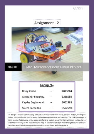
  • 1. 4/2/2012 Assignment - 2 202CDE EMBD. MICROPROCESSORS GROUP PROJECT Group NTP Divay Khatri – 4073084 Aleksandr Fedunov – 3238989 Cagdas Degirmenci – 3052983 Salem Bazeedan – 3522590 To design a robotic vehicle using a PIC18F4520 microcontroller board, stepper motors, Darlington Driver, photo reflective optical sensor, light dependent resistor and switches. The task is to design a Light Sensing Robot using all the above stuff and to make it search for light within an enclosed area with the boundary as the black tape and stop at a distance of 15cm from the light source and two switches which help to re-negotiates the path once collided with the obstacle.
  • 2. INDEX Contents Page No. Who did what? 2 Introduction 3–5 Design Process - Hardware Design 6–8 - Software Design 9 – 15 Implementation 16 – 19 - Code 20 – 25 - PCB 26 – 30 Components used 31 Test Methodology 32 – 34 Conclusion 35 References 36 Who did what? Divay Khatri The whole software thing + helped with the hardware part + helped with PCB design + report from design process till the end Aleksandr Fedunov Helped with the hardware part + Introduction and conclusion for the report Cagdas Degirmenci Helped with the hardware part + helped with PCB design Salem Bazeedan Helped with the hardware part And in the start of the assignment we discussed the logic about how to do this together. 2|P a ge
  • 3. Introduction: What is a robotic vehicle? The field of robotics encompasses a broad spectrum of technologies in which computational intelligence is embedded in physical machines, creating systems with capabilities far exceeding the core components alone. Such robotic systems are then able to carry out tasks that are unachievable by conventional machines, or even by humans working with conventional tools. The ability of a machine to move by itself, that is, “autonomously,” is one such capability that opens up an enormous range of applications that are uniquely suited to robotic systems. To be useful in real world, robots need to move safely in unstructured environments and achieve their given goals despite unexpected changes in their surroundings. The environments of real robots are rarely predictable or perfectly unknown so it does not make sense to make precise plans before moving. This report will describe how we designed and built a light sensing robot. The task is to build a light sensing robot using two LDR’s to sense the light and accordingly move the wheels, one opto sensor to remain within the boundary, two switches to change the direction of the robot when gets collided with an obstacle, all this on a PIC18F4520 microcontroller board, and a Darlington driver to control the locomotion aspect of the vehicle. Our first step was to understand how the robot should work and what things it needs to perform. If the sensors (LDR) sense bright light, i.e. approximately a distance of 15cm away from the robot, then the robot must stop. If the sensors sense extra light than the normal light, then the sensor which is having some extra light, the vehicle should move in that direction. If both the sensors sense the same amount of extra light then the vehicle should move in the forward direction. If the opto reflective sensors value is 0 then do all of the above steps else if it is 1 that means the robot is over the boundary, the black line. So it should move backwards and then turn to a direction and then again should start searching for extra light. If the switches gets pressed, that means the robot has collided with something (an obstacle) and it needs to change its way. When a switch gets pressed, the interrupt comes in. Let’s get into the detail of these steps, The robot should move within an enclosed black taped area which robot must sense via photo reflective optical sensor. The main task is that robot should search for a light source by using LDR’s (Light Dependant Resistors) and when it collides with an obstacle with the 3|P a ge
  • 4. lever switchers(bumpers) it should re-negotiate its path towards the light source. After robot reaches the light source it should stop at a small distance from it. We were given four weeks to complete this project for from both hardware and software aspects. This was not that tough task as we have successfully completed our first assignment – Line following robot few months ago. Some things were similar, some piece of the code was similar and we had to attach the sensors to the same vehicle platform. But there was a difference this time, logically if a vehicle has to move then one wheel should rotate in the clockwise direction and the other in the anti-clockwise direction to make the vehicle move but in actual both the wheel should move in the same direction (the forward direction to move forward and vice-versa). The thing which was changed for us was the polarity of the stepper motors we were using where we had to set the locomotion aspect of the wheels with both motors moving in the clockwise direction. Below we will discuss about the general idea as on the set-up with the stepper motors. Our objective for the first week was to find a voltage values for LDR’s (how it reflects the light) and resistor values for the LDR’s, Optical sensor and Lever switchers. To calculate values of the resistors we used data sheets of each component (sensor). Calculations are given in the main body, after the calculations we started attaching the sensors and the switches one by one to the breadboard and with the development board, the LDR’s using analogue to digital channel 0 and channel 1 to PORTA bit 0 and 1 assigned the decimal values to the code where it should follow the light source and stop at some distance from it (using 8 bits) and then tested it along with a stepper motors. The confirmation was that the LDR’s reacted well to the light and the stepper motors moved accordingly. The first week was over. On the second week our objective was to achieve the task with the interrupts by using lever switchers. The resistor values for this were found in the schematic given. We already knew from the lectures that we must use 2 interrupts, one low priority and the other high priority. The high interrupt have a privilege mode. For example if a low interrupt is currently doing the instruction, a high interrupt can easily interrupt the low interrupt but the vice-versa is not true. We completed this objective for the week and made the interrupts work. When one of the bumpers is pressed then the stepper motors do some steps, it moves in the backward direction, turn to either left or right and then move forward searching the light. Attaching the opto sensor was the last step so for the third week we arranged everything together including the opto sensor and compiled the code. Everything worked fine but we couldn’t stop the wheels at 15cm distance from the light source. After we saw it working, we recorded the video of the set-up which can be found below. 4|P a ge
  • 5. Then the fourth week we started connecting components on the robotic vehicle and make it move, the objective for the last week of the project. The video below can demonstrate how it works on the vehicle and can prove that the entire task was done successfully. What we were done so far is:  Stepper motors works with the LDR’s  Optical reflective sensor can avoid the black line  The lever switchers works perfectly fine as the interrupts and can perform the tasks to re-negotiate the obstacle  The LDR’s make the stepper motors move to follow the light and stops them at a given range The idea is to make the robotic vehicle within an enclosed black taped area and follow the light source. When it reaches the obstacle it must perform steps to re-negotiate it/avoid it and then again should follow the light source. If it reaches the black tape or the boundary it should change the direction. We made two videos showing the working of the light sensing robot: Set-up of the hardware (an in working with the individual parts) http://www.youtube.com/watch?v=6825V6opX7Q The moving robotic vehicle http://www.youtube.com/watch?v=qKiPZ4BL_vA 5|P a ge
  • 6. Design Process: Below is the diagram that shows the set-up of the hardware, with all the sensors, their respective resistors, the switches, PIC development board and the stepper motors. Or we can say the circuit diagram. 6|P a ge
  • 7. To understand more about this let us have a look at the UML diagram for the hardware design. UML activity diagram for Hardware Design 7|P a ge
  • 8. This is the general idea from hardware point of view about what is happening. Now let us have a look at how to make the robot move in forward and backward direction. From previous classes we figured out that for a full step sequence in a clockwise direction, the values for the steps should be: STEP 1 0x09 STEP 2 0x05 STEP 3 0x06 STEP 4 0x0A And thus for the full step sequence in an anticlockwise direction, the values for the steps should be reversed: STEP 1 0x0A STEP 2 0x06 STEP 3 0x05 STEP 4 0x09 This sequence applies only for one stepper motor but if we have to make two stepper motors move simultaneously then the stepping sequence will be: 1. Make both the motors move in clockwise direction: STEP 1 0x99 STEP 2 0x55 STEP 3 0x66 STEP 4 0xAA 2. Make both the motors move in anti-clockwise direction: STEP 1 0xAA STEP 2 0x66 STEP 3 0x55 STEP 4 0x99 3. Make one motor in anti-clockwise direction and the other in clockwise direction STEP 1 0xA9 STEP 2 0x65 STEP 3 0x56 STEP 4 0x9A 8|P a ge
  • 9. This was the general idea of how to make the motors move. In our Project we have connected 4-7 bits of PORTD with Motor 2 and 0-3 bits of PORTD with Motor 1. Now let us have a look at the software design. Software design: After making the connections according to the circuit as shown above, MPLAB was launched and a new project was created so as to program the PIC18f4520 through the ICD 3. We started programming the PIC in C language. 1. a. First we configured the operational parameters of the PIC by setting OSC mode to HS high speed clock. b. Then the watchdog timer was set to OFF. c. Low Voltage Programming was also set to OFF. d. And a state to compile without extra Debug compile code was set. 2. Header files (Include files) were included in the program a. #include <p18f4520.h> - device used is the PICF4520 b. #include <delays.h> - to include the delay routines c. #include <adc.h> - to include the files used in the analogue to digital conversion d. #include <stdio.h> - this describes the interface to the library which contains basic I/O functions e. #include <portb.h> - to set port b for interrupts and use the default registers defined in it 3. The stepping sequence was figured out in the previous classes and according to that stepping sequence where the stepper motors did a clockwise and anti-clockwise turn; the steps were assigned hexadecimal values. We know that 0x00 For the 0-3 bits of the PORT Used to represent hexadecimal values For the 4-7 bits of the PORT 9|P a ge
  • 10. Thus to make a robotic vehicle move in the forward direction, we need to make one motor move in anti-clockwise direction (i.e. Motor 1) and the other motor in clockwise direction (i.e. Motor 2) and we have to make changes in the directions of both the motors according to the response from the photo reflective optical sensors, light dependent resistors and the switches. But the robotic vehicle we were working on was having a different setting in the motor and thus we had to set both the wheel in clockwise direction in order to make the robot run. Practically, both the motors should move in the forward direction but logically both in the opposite directions but with our robotic vehicle the case was different and thus the stepping sequence in the end was changed. We have assigned appropriate hexadecimal values to the steps and they are: (you will see in comparison) When done on stepper motors (left side) and when done on the robotic vehicle (right side) STEP 1 0xA9 STEP 1 0x99 STEP 2 0x65 STEP 2 0x55 STEP 3 0x56 STEP 3 0x66 STEP 4 0x9A STEP 4 0xAA STEP 5 0xA0 STEP 5 0x90 STEP 6 0x60 STEP 6 0x50 STEP 7 0x50 STEP 7 0x60 STEP 8 0x90 STEP 8 0xA0 STEP 9 0x09 STEP 9 0x09 STEP 10 0x05 STEP 10 0x05 STEP 11 0x06 STEP 11 0x06 STEP 12 0x0A STEP 12 0x0A STEP 13 0x9A STEP 13 0xAA STEP 14 0x56 STEP 14 0x66 STEP 15 0x65 STEP 15 0x55 STEP 16 0xA9 STEP 16 0x99 4. Then we declared the interrupts according to the low and high priority and used the GOTO command to go to their respective definitions. 5. Then we initialized all the bits (0-7) of PORTD for outputs and all 7th bit of Port C for the input from opto sensor, 0 and 1st port bit of Port B for interrupts and 0 and 1st bit of Port 10 | P a g e
  • 11. A for inputs from both LDR’s. Also included a while loop (with while = 1) such that the code can run forever. 6. Then we included the code for the Analogue to Digital conversion twice, once for channel 0 and next for channel 1 and transferred that converted digital value to the respective LDR. 7. Now we compared the value of LED1, if 0 then proceed normally, else if 1 then go to the else part. 8. If LED1 =0, starts the basic logic to control the locomotion aspect of the vehicle which uses the ADC converted value to steer the robot. There are 5 conditions which can be included a. If LDR1 > LDR2 Then stop left stepper motor and move the right stepper motor in forward direction in order to move the robot to the left. b. If LDR2 > LDR1 Then stop right stepper motor and move the left stepper motor in forward direction in order to move the robot to the left. c. If LDR1 == LDR2 This situation occurs rarely; in this both the wheels move in the forward direction. d. If LDR1 and LDR2 are less than 245 (the voltage value of LDR at a distance of approx 15cm) then the robot should stop e. Another case can be if LDR1 and LDR2 both values are falling below a certain range which means there is no extra light and in that case the robot can rotate left or right by remaining at the same position. But we have not included this in the code as it was simply to follow the light source and stop 9. If LED1 = 1, starts the else part which is just a condition to move the robot backwards and turn to a direction. This case happens when the robot is over the black line and thus according to the code it can’t cross the black tape which acts as the boundary. 10. Then there are two switches in the hardware design which are bumpers, when the robot collides the switch gets pressed and acts as an interrupt and accordingly the interrupt function works. If switch 1 gets activated then the robot moves backwards, turn to right and move forward for some steps and then again starts following the light as it gets back into the main program. Similar happens when switch 2 gets activated. 11 | P a g e
  • 12. For the opto sensors and the light dependent resistors we need to find their resistor values using the data sheets from the manufacture of those sensors thus the calculations are given below: For opto sensor: RD = RL = RD = RL = For LDR’s: RD = 82.5 Ω RL = 25 GΩ 12 | P a g e
  • 13. Voltage Out – 320 V (maximum) Current – 75 mA (maximum) 1000 LUX - 400Ω 10 LUX - 9 kΩ VOUT = = = Rx = This was a general calculation. But the output never goes to complete 5V or to complete 0V; therefore using Vout as 4.3 volts and 0.7 volts the values of Rx comes out to be 2.457 KΩ and 1.465 KΩ. But as advised we had to use the values that we used during the normal exercises. The above software design and interrupt routine steps are presented through the UML activity diagrams, please see below. 13 | P a g e
  • 14. UML activity diagram for Software Design 14 | P a g e
  • 15. UML activity diagram for the Interrupt sequence 15 | P a g e
  • 16. Implementation of the design Implementation of the design wasn’t challenging as we have already completed assignment 1 and the exercises we have carried out since the start of the module. As we knew about the previous components, the opto sensors, the LDRs there was just the interrupts which was new to us. But that was also done easily. Setting up the connection and understanding how the circuit worked was quiet easy. When we came across a problem; such as unresponsive equipment, it did not take us long to figure out what the problem was because we were familiar with the equipment. Having these advantages we quickly set-up the circuit. We have explained below the circuit step by step and explained further the reason of these connections. The schematic was given to us and we had to arrange the circuit in the same manner. 16 | P a g e
  • 17. This is the set-up of the hardware with individual components. About the hardware set up: a) Firstly we connected the PIC I/O board and the PIC development board with a 10-pin ribbon cable. This connection was made from the PIC I/O board to Port D on the development board. Using this connection we were able to cross-over 8-bit of information. b) Then with an 8-way connected wire, we have connected I/O board with the microcontroller’s input. c) The output of the microcontroller is then connected to the stepper motors. 0-3 bits to one of the stepper motor and 4-7 bits into the other stepper motor. d) After completing the main connections, we moved on to power supply connections where 5V were connected to most of the boards and 12V was only connected to the stepper motors. e) We then connected the optical sensor, the LDR, and the switches with their respective resistors to the bread board which was already powered by 5V. 17 | P a g e
  • 18. f) We then connected the output of these sensors to the respective ports in the PIC microcontroller board. g) Finally with an RJ11 cable, we connected the PIC board to MBLAB ICD3 (programmer and debugger) device. h) Then connected the 4 white LED light source with +5v and GND and started checking whether the hardware responds accordingly or not. While connecting the circuit we did encounter simple problems. They are seen simple because we easily found solutions to them. For example when we were planning on how to stop the robotic vehicle when closer to the light source, we come across logical difficulties. We were first trying to use a 10 bit adc channel and the values with that were coming in the range of greater than 800 for the voltage output of LDR but we resolved this by using a 8 bit which returned a voltage output of 245 (at a distance we needed). The table below shows different voltage output values at different sensitivities of the light. Light Sensitivity LDR1 LDR2 Normal Light 224 volts 221 volts Bright Light 246 volts 245 volts Medium bright Light 244 volts 244 volts The ‘brain` of the circuit is the PIC18F4520 and it has been programmed with a C language code which we have written and it works according to our preferences. Firstly we have connected the Darlington board with the Port D on the PIC. The port D on the PIC is an output interface and we use this output to control the stepper motors. The pins 0-3 are programmed to use the LDR1 corresponding to motor 1 and the pins 4-7 are programmed to use the LDR2 corresponding to motor2. The pins 9 and 10 are for ground connections. A 5V power supply was connected to the PIC Board. The other end of the Darlington driver is used to connect the Stepping motors on the robotic vehicle. The wires coming out windings of the stepping motors had to be individually connected on the Darlington board. The wires have to be connected in the pattern of White, White, Blue, Blue, then White, White and Blue, Blue. The Darlington driver was powered with 12Volts. The stepping motors surely needed power to run so we also connected the two with 12Volts through +Vmotor connection. The next connection we made was connecting the two LDR’s, the two switches and one optical reflective sensor to the PIC board. We configured our program in such way that each sensor was assigned to a stepping motor. In simplicity each sensor acted as an eye for the motor it was assigned to. The connection of the hardware components is still the same as defined in the design section. 18 | P a g e
  • 19. LDR Opto sensor The Opto Sensor output goes to Port C bit 7 acts as the input where it detects a black line; LDR1 and LDR2 through an ADC bit 0 and 1 of Port A and the Lever Switches to Port B 0 and 1. These inputs are configured in the program so the motors act on these values. Then we programmed the PIC microcontroller through ICD3. The code is given below: 19 | P a g e
  • 20. The program code in ‘C’ for the Light Sensing Robot /* Group Ntp - Light Sensing Robot Divay Khatri - 4073084 Aleksandr Fedunov - 3238989 Cagdas Degirmenci - 3052983 Salem Bazeedan - 3522590 */ // configure operational parameters of the PIC #pragma config OSC = HS #pragma config WDT = OFF #pragma config MCLRE = ON #pragma config DEBUG = OFF #pragma config LVP = OFF // header files #include<p18f4520.h> #include<delays.h> #include<portb.h> #include<stdio.h> #include<adc.h> #define LED1 PORTCbits.RC7 // define PORTC bit 7 for output from opto sensor // Stepping Sequence - according to the robotic vehicle // move forward unsigned char STEP1 = 0x99; unsigned char STEP2 = 0x55; unsigned char STEP3 = 0x66; unsigned char STEP4 = 0xAA; // stop left and move right unsigned char STEP5 = 0x90; unsigned char STEP6 = 0x50; unsigned char STEP7 = 0x60; unsigned char STEP8 = 0xA0; // stop right and move left unsigned char STEP9 = 0x09; unsigned char STEP10 = 0x05; unsigned char STEP11 = 0x06; unsigned char STEP12 = 0x0A; // stop the motors unsigned char STEP13 = 0x00; // LDR1 = left and LDR2 = right void high_isr (void); void low_isr (void); void INT0_ISR(void); //Prototype for the goto that follows void INT1_ISR(void); 20 | P a g e
  • 21. #pragma code high_interrupt = 0x08 //High Interrupt vector @ 0x08 void high_interrupt (void) // At loc 0x08 we place the assembler instruction GOTO { _asm // This is the assembly code at vector location GOTO high_isr _endasm } #pragma code #pragma interrupt high_isr void high_isr (void) { if (INTCONbits.INT0IF == 1) // Was interrupt caused by INT0 ? INT0_ISR (); // Yes , execute INT0 program } #pragma code low_interrupt = 0x18 void low_interrupt (void) // At loc 0x08 we place the assembler instruction GOTO { _asm // This is the assembly code at vector location GOTO low_isr _endasm } #pragma code // used to allow linker to locate remaining code #pragma interruptlow low_isr void low_isr (void) { if (INTCON3bits.INT1IF == 1) INT1_ISR (); } int LDR1 = 0; int LDR2 = 0; int i; void main (void) { ADCON1 = 0xFF; TRISD = 0x00; LATD = 0x00; TRISA = 0xFF; TRISC = 0xFF; // setting the interrupts INTCONbits.INT0IE = 1; //Enable INT0 interrupts INTCONbits.INT0IF = 0; // Clear INT0 Interrupt flag INTCON3bits.INT1IE = 1; //Enable INT0 interrupts INTCON3bits.INT1IF = 0; // Clear INT0 Interrupt flag INTCON3bits.INT1IP = 0; RCONbits.IPEN = 1; INTCONbits.GIE = 1; // Enable global interrupts INTCONbits.GIEL = 1; INTCONbits.GIEH = 1; 21 | P a g e
  • 22. while(1) { OpenADC(ADC_FOSC_32 & ADC_LEFT_JUST & ADC_0_TAD,ADC_CH0 & ADC_INT_OFF & ADC_VREFPLUS_VDD & ADC_VREFMINUS_VSS, 0b1011); SetChanADC(ADC_CH0); /* Selects the pin used as i/p to the */ Delay10TCYx(20); /* delay for 200 instruction cycles */ ConvertADC( ); /* start A/D conversion */ while(BusyADC( )); /* wait for completion */ LDR1 = ADRESH; OpenADC(ADC_FOSC_32 & ADC_LEFT_JUST & ADC_0_TAD,ADC_CH1 & ADC_INT_OFF & ADC_VREFPLUS_VDD & ADC_VREFMINUS_VSS, 0b1011); SetChanADC(ADC_CH1); /* Selects the pin used as i/p to the */ Delay10TCYx(20); /* delay for 200 instruction cycles */ ConvertADC( ); /* start A/D conversion */ while(BusyADC( )); /* wait for completion */ LDR2 = ADRESH; if(LED1 == 0) { //LDR's controlling stepper motors // to check if ldr greater than ambient light and less than 15cm light if(LDR1 <= 245 && LDR2 <=245) { if(LDR1 > LDR2) { LATD = STEP5; Delay10KTCYx(12); LATD = STEP6; Delay10KTCYx(12); LATD = STEP7; Delay10KTCYx(12); LATD = STEP8; Delay10KTCYx(12); } else if(LDR2 > LDR1) { LATD = STEP9; Delay10KTCYx(12); LATD = STEP10; Delay10KTCYx(12); LATD = STEP11; Delay10KTCYx(12); LATD = STEP12; Delay10KTCYx(12); } 22 | P a g e
  • 23. else if(LDR2 == LDR1) { LATD = STEP1; Delay10KTCYx(12); LATD = STEP2; Delay10KTCYx(12); LATD = STEP3; Delay10KTCYx(12); LATD = STEP4; Delay10KTCYx(12); } } else { LATD = STEP13; Delay10KTCYx(12); } } else if(LED1 == 1) { for(i=0;i<14;i++) { LATD = STEP4; Delay10KTCYx(12); LATD = STEP3; Delay10KTCYx(12); LATD = STEP2; Delay10KTCYx(12); LATD = STEP1; Delay10KTCYx(12); } for(i=0;i<14;i++) { LATD = STEP5; Delay10KTCYx(12); LATD = STEP6; Delay10KTCYx(12); LATD = STEP7; Delay10KTCYx(12); LATD = STEP8; Delay10KTCYx(12); } } } } 23 | P a g e
  • 24. // Interrupt routine INT0_ISR void INT0_ISR (void) // This is the interrupt service routine { for(i=0;i<7;i++) { // reverse; (for 3 times) LATD = STEP4; Delay10KTCYx(12); LATD = STEP3; Delay10KTCYx(12); LATD = STEP2; Delay10KTCYx(12); LATD = STEP1; Delay10KTCYx(12); } for(i=0;i<5;i++) { // stop right wheel and move left wheel (2 times) LATD = STEP9; Delay10KTCYx(12); LATD = STEP10; Delay10KTCYx(12); LATD = STEP11; Delay10KTCYx(12); LATD = STEP12; Delay10KTCYx(12); } for(i=0;i<4;i++) { // go forward; (1 time) LATD = STEP1; Delay10KTCYx(12); LATD = STEP2; Delay10KTCYx(12); LATD = STEP3; Delay10KTCYx(12); LATD = STEP4; Delay10KTCYx(12); } INTCONbits.INT0IF = 0; // Clear INT0 flag before returning to main program INTCON3bits.INT1IF = 0; // Clear INT0 flag before returning to main program } 24 | P a g e
  • 25. void INT1_ISR (void) // This is the interrupt service routine { for(i=0;i<7;i++) { // reverse; (for 3 times) LATD = STEP4; Delay10KTCYx(12); LATD = STEP3; Delay10KTCYx(12); LATD = STEP2; Delay10KTCYx(12); LATD = STEP1; Delay10KTCYx(12); } for(i=0;i<5;i++) { // stop left wheel and move right wheel (2 times) LATD = STEP5; Delay10KTCYx(12); LATD = STEP6; Delay10KTCYx(12); LATD = STEP7; Delay10KTCYx(12); LATD = STEP8; Delay10KTCYx(12); } for(i=0;i<4;i++) { // go forward; (1 time) LATD = STEP1; Delay10KTCYx(12); LATD = STEP2; Delay10KTCYx(12); LATD = STEP3; Delay10KTCYx(12); LATD = STEP4; Delay10KTCYx(12); } INTCONbits.INT0IF = 0; // Clear INT0 flag before returning to main program INTCON3bits.INT1IF = 0; // Clear INT0 flag before returning to main program } 25 | P a g e
  • 26. Now let’s have a look at the PCB design of the circuit (2-D and 3-D images). 26 | P a g e
  • 27. 27 | P a g e
  • 28. 28 | P a g e
  • 29. 29 | P a g e
  • 30. 30 | P a g e
  • 31. Project Components The components we used are given below and from where to buy. Component Name Cost Link 2 LDR’s 2 x £2.01 = £4.02 http://uk.farnell.com/silonex/norps-12/light- dependent-resistor/dp/327700 1 PIC18F4520 £4.72 http://www.rapidonline.com/Electronic- microcontroller Components/PIC18Fwxyz-Enhanced-Flash- microcontroller-64435/?sid=2fbad005-5de5- 4e06-b030-abb943273caf 1 Photo reflective £4.30 http://uk.mouser.com/search/ProductDetail.as optical sensor px?qs=iblIa22dKKR%2F8%2FPojtStag%3D%3D& cm_mmc=findchips-_-na-_-na-_- na&extra=index=4%7Cquery=OPB743%7Cqty= 0 2 Stepper Motors 2x£8.35 = £16.70 http://www.rapidonline.com/Electrical- Power/2-Phase-Bipolar-Stepper-Motor-12v-37- 0507/?sid=09feedbc-9699-47dc-9868- df23ccdca7f3 Copper wire £2.83 http://www.rapidonline.com/Education/Gilt- copper-wire-83192/?sid=369bfaaf-db6a-464f- a38f-04f214c6ae63 Darlington Driver £5.09 http://uk.farnell.com/allegro- microsystems/a6841sa-t/darlington-driver- serial-8bit-5841/dp/1202821 Microchip ICD3 £124.88 http://uk.farnell.com/microchip/dv164035/kit- evaluation-icd3/dp/1664878 In total by spending £161.66 + miscellaneous charges (power supply and breadboard) we can build this light sensing robotic vehicle and program it as well. 31 | P a g e
  • 32. Test Methodology This design was not built at once. We did it in parts and noticed how the thing works and then reversed it and saw how it works and noted down the changes. First we set up the hardware with just one stepper motor and saw the movement. And programmed PORTD 0-3 bits according to this pattern STEP 1 0x09 STEP 2 0x05 STEP 3 0x06 STEP 4 0x0A This made the stepper motor move in a full step sequence in a clockwise direction. And revering these values made the stepper motor move in a full step sequence in an anti- clockwise direction. STEP 1 0x0A STEP 2 0x06 STEP 3 0x05 STEP 4 0x09 We understood that on reversing the code the movement of the stepper motor changed. Now we attached another stepper motor to PORTD 4-7 bits and tried making both the motors move at the same time. Since we knew the concept thus changed the values of steps to: 32 | P a g e
  • 33. STEP 1 0xA9 STEP 2 0x65 STEP 3 0x56 STEP 4 0x9A We kept one value to be ‘9’ and other to be ‘A’ because when a car moves we know that the tires of the car moves in the same direction but the motor which makes them move actually rotate in opposite directions. This concept we applied here and while making changes to the hexadecimal values of the steps we kept in mind to make one motor rotate in clockwise direction and the other in anti-clockwise direction. This is the general case but with the robotic vehicle we worked on, with that we had to move both the wheels in the same clockwise direction logically as well. When we completed the investigation of the stepper motors then we started dealing with the photo reflective optical sensors and started testing them on the black line and on other surface as well and found that when they were faced down on some other surface then get the light in the receiver and thus completes the connection and returns a value of ZERO, but when placed faced down on a black surface, the receiver receives no light and the connection doesn’t get complete and returns a value ONE. So we were sure that when placed on a black surface the sensors return a value 1 and when on other surface it returns a value 0. We then connected the opto sensor to PORTC bits 7. Then we connected the multi meter with the LDR and threw light over them and recorded the change in the voltage with respect to bright and low light conditions and the output value of the voltage from the LDR’s according to different light sensitivities are: Light Sensitivity LDR1 LDR2 Normal Light 224 volts 221 volts Bright Light 246 volts 245 volts Medium bright Light 244 volts 244 volts We then compared both the values of LDR1 and LDR2 and assigned a pattern of stepping sequence to them. This was just a bit of the whole code to give an idea how the conditions were made. Example: if(LDR1 <= 245 && LDR2 <=245) then to the light searching operation and move towards the light and if not then stop the wheels. And the values were read into the PIC through an Analogue to Digital channel where the analogue signal gets converted to digital signal. 33 | P a g e
  • 34. This was done by Analogue to Digital conversion code. OpenADC(ADC_FOSC_32 & ADC_LEFT_JUST & ADC_0_TAD,ADC_CH0 & ADC_INT_OFF & ADC_VREFPLUS_VDD & ADC_VREFMINUS_VSS, 0b1011); SetChanADC(ADC_CH0); /* Selects the pin used as i/p to the */ Delay10TCYx(20); /* delay for 200 instruction cycles */ ConvertADC( ); /* start A/D conversion */ while(BusyADC( )); /* wait for completion */ output = ADRESH; And similarly for the channel 1, now LDR1 and LDR2 contains the converted digital signal which we need to compare with our decimal values of 15 cm, far away or closer which is We know that 5v = 256 if we deal with 8 bit ADC channel Using a programmer calculator, we found out Analogue voltage Decimal Value 8-bit binary value 5 volts 256 1 0000 0000 2.5 volts 128 0 1000 0000 4.40 volts 224 0 1110 0000 4.83 volts 246 0 1111 0110 4.78 volts 244 0 1111 0100 By clubbing the stepping sequence, the photo reflective optical sensors and the light dependent sensors code the main function of the .c file was written and by clubbing the interrupt code for the lever switches the interrupt routine was written. This was the design process and the testing methodology including the UML activity diagrams for Hardware and Software design for the robotic vehicle. 34 | P a g e
  • 35. Conclusion: The group assignment we carried out helped us having a wider view on electronics and its integration with software. We already got an idea of ‘The World of Logic and Circuits’ from assignment 1 but this time it was an amazing experience to know that we can do so much with circuits and esp. learning to design a PCB. We understood how this integration works. Now we feel one more step closer to be an engineer and once again proved to ourselves that this was the right choice for our professional life. This project also made us feel more confident on practical basis, where we felt as if we were working with this equipment for a long time. Working as a group in this project contributed in our success, because we all were not familiar with every aspect of the requirements. One of us was good with programming, one with the hardware part as in the circuit part and one with both. Logical thinking is a very important aspect to build any circuit that has no idea of what environment it is going to deal with, and this aspect was in all three of us. We always thought a problem logically first, worked that logic out on paper and one of us decided how we will work this in coding, the other decided how this will work with the hardware and we started setting up the hardware and writing the code so as not to waste any time. By doing this project together we ended up getting knowledge and information on the areas we were weak in through sharing our ideas and thoughts with each other. During the last three weeks where we carried out several tasks, we came across some problems. For example at one point the sensor we were using was not working so we couldn’t stop the car. It took us a bit of time to find out it was the sensor which wasn’t working, as we had to individually test every component and wire connections. Then the LDR’s didn’t work well and we tried to search for a problem but logically everything was fine. It took time to find that LDR’s didn’t worked fine with the opto-sensor. Also now we understand that if in the circuit shows a different path for the power supply then they should connect to the different power supplies. Other than that we didn’t encounter any major problems, and carried out the required tasks easily. By doing this project as a group we all getting knowledge and information on the areas that we didn’t know at all such as interrupts. Also, it gave us a great time spending where we can share our ideas and thoughts with each other. After we built the circuit and programmed the PIC we decided to test the robotic vehicle. It would’ve been amazing if everything went perfect at first stage, but unfortunately this didn’t happen. We had to modify a lot of little things like, the distance between the sensors and the surface, change the coding (as the vehicle we were working on had different polarity stuff); as the vehicle was moving faster than it should and sometimes it got out of its track (black tape). As mentioned before with a bit of modifying and adjustments these problems were overcome. Finally when we finished the robotic vehicle and were satisfied with the design and the coding. So we placed the robot in an enclosed area with black tape around, placed some obstacles in between and a light source. Then we made the robot run and this time we were really satisfied as it smoothly moved in the area searching for light and stopped at just some distance from it. This made us feel good as all the hard work we put in, resulted in our success. Now we wish to work on more projects like this, I wish there was some homework to design a robot to do this in your holidays. But we carried out this successfully. 35 | P a g e
  • 36. References: The ADC conversion code: http://web1.eng.coventry.ac.uk/panos/info/Experiments/Micros/202CDE/ADC%20Lab%20PIC18.pdf For the configuration settings of the PIC http://web1.eng.coventry.ac.uk/panos/info/Experiments/Micros/202CDE/Config%20settings%20PIC 18.pdf For the delay functions used in the code http://web1.eng.coventry.ac.uk/panos/info/Experiments/Micros/202CDE/Delay%20Library%20MCC 18.pdf For the MCC18 C compiler http://web1.eng.coventry.ac.uk/panos/info/Experiments/Micros/202CDE/Intro%20to%20the%20M CC18%20C%20compiler.pdf For the sensors http://web1.eng.coventry.ac.uk/panos/info/Experiments/Micros/202CDE/Opto%20Sensors.pdf For the stepper motors http://web1.eng.coventry.ac.uk/panos/info/Experiments/Micros/202CDE/Stepper%20Motor%20Exp eriment%20PIC.pdf Opto sensors http://web1.eng.coventry.ac.uk/panos/info/Experiments/Micros/202CDE/Opto%20Sensors.pdf Interrupts http://web1.eng.coventry.ac.uk/panos/info/Experiments/Micros/202CDE/Interrupts%20intro%20% 20PIC18%20.pdf Light Dependent Resistors http://web1.eng.coventry.ac.uk/panos/info/Experiments/Micros/202CDE/Interrupts%20intro%20% 20PIC18%20.pdf 36 | P a g e