2. Capacitance
This is defined as the charge per unit voltage that the device is
capable of maintaining.
The symbol for capacitance is C, the unit F (Farad).
C = q/V
The circuit symbol is
3. Capacitors
A capacitor is a device that stores charge. It can be charged and
discharged through a circuit.
The simplest device is two parallel plates. The gap between the
plates can be filled with a range of media:
1) Air
2) Vacuum
3) Dielectric (a non-conductive material eg plastic, ceramic)
4. Calculate
1. A 9V battery is connected across a 200 μF capacitor. What is
the charge on the plates of the capacitor?
2. A circuit is used to charge a capacitor, a current of 5.4
milliamps flows for 2 minutes. Determine the charge acquired by
the capacitor and the capacitance for the capacitor if the
potential difference is 120V.
5. Calculate
1. A 9V battery is connected across a 200 μF capacitor. What is
the charge on the plates of the capacitor?
q = c.v = 2x 10-4 x 9 = 1.8 x 10⁻³ C
2. A circuit is used to charge a capacitor, a current of 5.4
milliamps flows for 2 minutes. Determine the charge acquired by
the capacitor and the capacitance for the capacitor if the
potential difference is 120V.
Q = It = 5.4 x 10-3 x 2 x 60 = 0.648
C = q/v = 0.648/ 120 = 5.4 mC
6. In circuits
Capacitors can be placed in series or in parallel within a circuit.
Capacitors in parallel behave similar to resistors in series – that is
the capacitance sums.
C = C1 + C2
7. Can you analyse the previous circuit to show
that C = C1 + C2 ?
Hint – consider potential difference.
8. Can you analyse the previous circuit to show
that C = C1 + C2 ?
Hint – consider potential difference.
The pd across each capacitor is V because they are in parallel so,
V1 = V2= V
C = q/V so C1 = q1/V and C2 = q2/V
Charge must be conserved and so q = q1 + q2
Therefore, CV = C1V + C2V
C = C1 + C2
10. Determine…
Capacitors of value 275pF and 35pF and placed in a circuit with
a 3V battery.
Compare the “equivalent” capacitor value for
a) In series
b) In parallel
Now determine the charge on each capacitor
11. Energy stored in charged capacitor
We can determine the work done to store charge on a capacitor using graphical
means.
If we plot voltage and charge, the gradient of the graph will be the capacitance and
the area under the graph will be the work done (or energy stored).
E = V/2 x q
But C = q/V
So E = ½ C V2
Charge, q
p.d, V
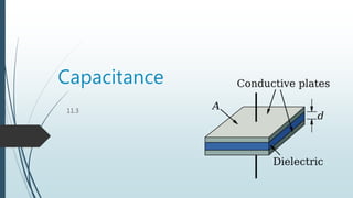
12. Dielectrics
A parallel plate capacitor has limitations as to the charge it can
hold. The capacitance is affected by the cross-sectional area of
the plates, the separation of the plates and the dielectric
properties of the medium between them. This is expressed in the
following equation:
13. The permittivity of free space is ε0.
And the dielectric material reduces the ratio of ε0/ ε because the
molecules in the material are polarized by the electric field. This
results in an opposing field.
14. Calculate
A 250 F capacitor will be manufactured using a dielectric
having a permittivity of 2.500 and circular plates having a
diameter of 1.80 cm.
Find the plate separation?
Is this proposal realistic?
15. Calculate
A 250 F capacitor will be manufactured using a dielectric
having a permittivity of 2.500 and circular plates having a
diameter of 1.80 cm.
Find the plate separation?
A=πd2/4 = π x0.0182/4 = 0.000254
d= A/C = 2.5 x 8.85x10-12x0.000254/250x10-6 = 2.25x10⁻¹¹
Is this proposal realistic?
No – the separation is smaller than the size of an atom.
16. Questions
Why is it important to keep the cross-sectional area of
the plates small?
What is the purpose of the dielectric?
Is there a force between the plates of a capacitor?
What do we use capacitors for?
TOK
17. Uses for capacitors
Smoothing voltages
Storing small amounts of energy
Tuning circuits
Filtering (dc from ac)
Timing circuits
18.
19. Charging capacitor
A capacitor can be charged, or discharged, when
placed in parallel with a resistor and a power
source. This type of circuit is referred to as an RC
circuit.
The resistance allows the time of the charging, or
discharging, to be controlled. The current time
graph (or pd time graph) will be exponential in
nature.
20. Time constant
The resulting equations are:
and
I = I0 e -t /
Where τ is the time constant = RC
q = q0 e -t /
V = V0 e -t /
21. Question
A 1.50-V cell is connected to a 275 F capacitor in the circuit
shown.
(a) Sketch a graph of the voltmeter reading after the switch is
closed.
(b) Sketch a graph of the ammeter reading after the switch is
closed.
22. Question-solution
A 1.50-V cell is connected to a 275 F capacitor in the circuit
shown.
(a) Sketch a graph of the voltmeter reading after the switch is
closed.
(b) Sketch a graph of the ammeter reading after the switch is
closed. V/V
t
1.50
I/A
t
MAX
23. Question
A 25 F capacitor is charged to 6.00 V. It is then discharged
through a 2.0 M resistor.
Find the instantaneous voltage at t = 1250 s.
Then find the instantaneous current using Ohm’s law.
24. Question
A 250 F capacitor is charged to 6.00 V. It is then discharged through a 2.0
M resistor.
Find the instantaneous voltage at t = 1250 s.
Use q0 = CV = 25 x 10-6 x 6 = 0.000125 C,
and = 2 x 106 x 250 x 10-6 =500 s.
Substitute t = 1250 s into V = V0 e -t / .
V = 6.00 e -1250 /500 = 0.49 V.
Then find the instantaneous current using Ohm’s law.
I = V / R
= 0.49 / 2.0106
= 2.4610 -7 A.