Redi-Rock Burt Lake Road Wall - Eagle West Precast
•
0 j'aime•175 vues

Learn how "Redi-Rock’s large unit size and weight combined with its interface shear capacity made the construction of the Burt Lake Road Wall a viable solution," in Cheboygan, Michigan.

Recommandé
Contenu connexe
Plus de Eagle West Cranes JB
Plus de Eagle West Cranes JB (20)
Dernier
Dernier (20)
Redi-Rock Burt Lake Road Wall - Eagle West Precast
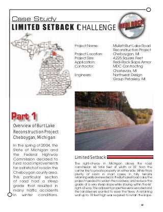
- 1. Case Study L I M I T E D S ET B A C K C H A L L E N G E Project Name: Mullett-Burt Lake Road Reconstruction Project Project Location: Cheboygan, MI Project Size: 4,225 Square Feet Application: Redi-Rock Slope Armor Contractor: MDC Contracting Charlevoix, MI Engineers: Northwest Design Group Petoskey, MI Part 1 Overview of Burt Lake Reconstruction Project Cheboygan, Michigan In the spring of 2004, the State of Michigan and the Federal Highway Commission decided to Limited Setback fund road improvements The right-of-way in Michigan allows the road for a stretch of road in the commission 66 total feet of width or 33’ from the center line to private property on either side. While this is Cheboygan county area. plenty of room in most cases, in hilly terrains This particular section retaining walls are needed. In the Burt Lake Road case, the of road had a steep project needed to widen the roadway and reduce the grade of a very steep slope while staying within the 66’ grade that resulted in right-of-way. The adjacent properties were wooded and many traffic accidents the landowners wanted to save the trees. A retaining in winter conditions. wall up to 18 feet high was required to retain the slope. 44
- 2. Potential solutions included Part 2 sheet piling, poured in place concrete and geo-grid reinforced Design Criteria and the segmental retaining walls. Redi-Rock Solution However, these solutions were not The modular block wall, can be desirable due to problems such analyzed as a rigid body as suggested by as excessive cost, inabliity to be AASHTO* (section 5.9) The net overturning constructed within the right-of-way, moment for the site specific conditions is and were not aesthetically pleasing. into the slope. Therefore, the wall behaves more like slope armor or cladding than a retaining wall. From an overturning Redi-Rock Solution perspective, the soil is actually supporting MDC Contracting proposed using the wall. Redi-Rock, a 2,500 pound modular 1) Sliding Resistance block with a 9” setback to create Interface shear between the a wall with a batter angle at 2V:1H modular units is a significant design requiring no geo-grid. The wall point. The shear loads are transferred needed to be buried up to between Redi-Rock units by a 10” 6 feet at the tallest part to shear knob-shear groove joint. This joint provide global stability and base has been non-destructively tested to sliding resistance. Redi-Rock’s to 9,000 pounds per foot. Theoretical large unit size and weight shear strength is significantly higher. combined with its interface shear capacity made the construction 2) Base Sliding between the wall and the soil of the Burt Lake Road Wall a viable Sliding resistance is frequently solution. Redi-Rock provided the the controlling criteria for tall following significant advantages. non-reinforced walls. Appropriately First, it provided a wall solution sized site specific foundations are within the limited space constraints. required to provide sliding resistance. Second, it is a cost effective These foundations may incorporate solution, fast and efficient to install, soil anchors or be buried sufficiently and required no easements. Third, deep enough to provide sliding resistance. Redi-Rock is a durable wet cast concrete unit that 3) Global Stability performs Stability of the soil well in the behind the wall must freeze-thaw also be checked for environment tall non-reinforced of northern walls. Increasing the Michigan. wall bury depth or Lastly, the foundation size are superior common methods aesthetic employed to address appearance global stability. of Redi- Rock. For more information on Redi-Rock Retaining Wall systems, please contact us at 866-222-8400 or on the web at www.redi-rock.com. * American Association of State Highway and Transportation Officials, Standard Specifications for Highway Bridges, 17th edition, Section 5.9