SlideShare une entreprise Scribd logo
1  sur  1
Télécharger pour lire hors ligne
ASSEMBLY INSTRUCTIONS FOR ROPE CUTTER TWINFAST® FOR SHAFT LINE
NOTICE DE MONTAGE POUR COUPE ORIN TWINFAST® SUR ARBRE D’HELICE
Fig.1 Fig. 2 Fig. 3 Fig. 4
 Clean the propeller shaft (3).
 Fit the rope cutter, with its guard (5) on, to the propeller shaft (3) taking care over the direction of the rope cutter (see diagrams).
 Position the rope cutter (2) between 6 and 10 mm from the stern tube (4) taking the propeller shaft slip into account (3) (connected to the engine power).
 Remove a protective split ring (5) so that you can tighten the fixing screw(s) and thus mark the propeller shaft (3).
 Unscrew the fixing screw(s) and replace the protective split ring (5).
 Remove the rope cutter (2) with its guard (5) on and make an indentation (using a drill bit) on the propeller shaft (3) over the mark(s) left by the screw(s).
 Replace the razor shaft (2) with its guard (5) on to the propeller shaft (3) repositioning it over the indentation(s).
 Remove a protective split ring (5) to gain access to the fixing screw(s).
 Place the screws with locking system (supplied in the kit) into the hole(s) tapped into the rope cutter (2).
 Tighten the fixing screw(s) using the spanner supplied in the kit.
 Replace the protective split ring (5).
REMEMBER TO REMOVE THE GUARD BEFORE LAUNCHING
When the boat is out of the water, replace the guard (5) on the rope cutter (2)
1. Nettoyer l’arbre d’hélice (3).
2. Monter le coupe orin, équipé de sa protection (5), sur l’arbre d’hélice (3) en prenant garde au sens du coupe orin (voir les schémas).
3. Positionner le coupe orin (2) entre 6 et 10 mm du tube d’étambot (4) en tenant compte du recul de l’arbre d’hélice (3) (lié à la puissance moteur).
4. Retirer une demi-coquille de protection (5) pour pouvoir serrer la(les) vis de fixation afin de marquer l’arbre d’hélice (3).
5. Desserrer la(les) vis de fixation et remettre la demi-coquille de protection (5).
6. Retirer le coupe orin (2) équipé de sa protection (5) et faire une empreinte (à l’aide d’un forêt) sur l’arbre d’hélice (3) sur la(les) marque(s) laissée(s) par la(les) vis.
7. Remonter le coupe orin (2) équipé de sa protection (5) sur l’arbre d’hélice (3) en le repositionnant sur l’(les) empreinte(s).
8. Retirer une demi-coquille de protection (5) pour pouvoir accéder à la(aux) vis de fixation.
9. Mettre du frein filet (fourni dans le kit) dans le(les) trou(s) taraudée(s) du coupe orin (2).
10. Serrer la(les) vis de fixation avec la clé fournie dans le kit.
11. Remettre la demi-coquille de protection (5).
PENSER A RETIRER LA PROTECTION AVANT LA MISE A L’EAU.
Lorsque le bateau et hors d’eau, remettre la protection (5) sur le coupe orin (2).
As ROPE CUTTER are sharp, BE
AWARE of the risk of INJURY, in
particular, the risk of CUTS
Le COUPE ORIN est COUPANT,
attention aux risques de
BLESSURES, en particulier aux
COUPURES
ESPAÑOL
 Limpiar el eje de la hélice (3)
 Montar el corta cabo, equipado con su protección (5), en el eje de la hélice (3) atendiendo al sentido del corte (ver esquemas)
 Colocar el corta cabo (2) entre 6 y 10 mm del tubo de codaste (4) teniendo en cuenta el retroceso del eje de la hélice (3) (según la potencia del motor)
 Retirar una semi-coquilla de protección (5) para poder apretar los tornillos de fijación para marcar el eje de la hélice (3)
 Dessapretar los tornillos de fijación y volver a poner la semi-coquilla de protección (5)
 Retirar el corta cabo (2) equipado con su protección (5) y hacer una señal (con una broca) en el eje de la hélice (3) sobre la marca dejada por los tornillos
 Volver a montar el corta cabo (2) equipado con su protección (5) en el eje de la hélice (3) volviéndolo a colocar sobre la señal
 Retirar una semi-coquilla de protección (5) para poder acceder a los tornillos de fijación
 Poner adhesivo (incluido en el kit) en el agujero de roca del corta cabo (2)
 Apretar los tornillos de fijación con la llave incluida en el kit
 Colocar la semi-coquilla de protección (5)
ANTES DE METER EN EL AGUA, RETIRAR LA PROTECCIÓN
Cuando el barco esté fuera del agua, poner la protección (5) en el corta cabo (2)
I TALI AN O
1. Pulire l'albero dell'elica (3).
2. Montare il taglia cavo, con la protezione (5), sull'albero dell'elica (3) facendo attenzione al senso del taglia cavo (vedere gli schemi).
3. Posizionare il taglia cavo (2) a 6-10 mm dall'anello del tubo (4), facendo attenzione al regresso dell'albero dell'elica (3) (legato alla potenza motore).
4. Togliere il semiguscio protettivo (5) per poter chiudere una o più viti di fissaggio e segnare l'albero dell'elica (3).
5. Svitare una o più viti di fissaggio e rimettere il semiguscio di protezione (5).
6. Togliere il taglia cavo (2) con la protezione (5) e fare un'impronta (con l'aiuto di una punta) sull'albero dell'elica (3) su uno o più segni lasciati da una o più viti.
7. Rimontare il taglia cavo (2) con la protezione (5) sull'albero dell'elica (3) posizionandolo nuovamente su una o più impronte.
8. Togliere il semiguscio di protezione (5) per poter accedere ad una o più viti di fissaggio.
9. Mettere il freno filetto (fornito nel kit) in uno o più fori filettati del taglia cavo (2).
10. Chiudere una o più viti di fissaggio con la chiave fornita nel kit.
11. Rimettere il semiguscio di protezione (5).
TOGLIERE LA PROTEZIONE PRIMA DI IMMERGERE IN ACQUA.
Quando l'imbarcazione è fuori dall'acqua, rimettere la protezione (5) sul taglia cavo (2).

Contenu connexe

Plus de emmanuelle bezzi

CHAISE A STRATIFIER BRONZE
CHAISE A STRATIFIER BRONZECHAISE A STRATIFIER BRONZE
CHAISE A STRATIFIER BRONZEemmanuelle bezzi
 
FRANCE HELICES en Corse du 14 au 17 novembre 2022
FRANCE HELICES en Corse du 14 au 17 novembre 2022FRANCE HELICES en Corse du 14 au 17 novembre 2022
FRANCE HELICES en Corse du 14 au 17 novembre 2022emmanuelle bezzi
 
MANUEL INSTALLATION PSS TYPE PRO 20 A 90 MM
MANUEL INSTALLATION PSS TYPE PRO 20 A 90 MM MANUEL INSTALLATION PSS TYPE PRO 20 A 90 MM
MANUEL INSTALLATION PSS TYPE PRO 20 A 90 MM emmanuelle bezzi
 
MANUEL INSTALLATION PSS TYPE A -27.10.2022.pdf
MANUEL INSTALLATION PSS TYPE A  -27.10.2022.pdfMANUEL INSTALLATION PSS TYPE A  -27.10.2022.pdf
MANUEL INSTALLATION PSS TYPE A -27.10.2022.pdfemmanuelle bezzi
 
REPARATION HELICE (80 x 100 cm) (2).pdf
REPARATION HELICE (80 x 100 cm) (2).pdfREPARATION HELICE (80 x 100 cm) (2).pdf
REPARATION HELICE (80 x 100 cm) (2).pdfemmanuelle bezzi
 
REPARATION HELICE 6 PALES
REPARATION HELICE 6 PALES REPARATION HELICE 6 PALES
REPARATION HELICE 6 PALES emmanuelle bezzi
 
press arab magazine France Helices_174.pdf
press arab magazine France Helices_174.pdfpress arab magazine France Helices_174.pdf
press arab magazine France Helices_174.pdfemmanuelle bezzi
 
REPARATION HELICE 4 PALES
REPARATION HELICE 4 PALES REPARATION HELICE 4 PALES
REPARATION HELICE 4 PALES emmanuelle bezzi
 
REPARATION HELICE 3 PALES BRONZE.pdf
REPARATION HELICE 3 PALES BRONZE.pdfREPARATION HELICE 3 PALES BRONZE.pdf
REPARATION HELICE 3 PALES BRONZE.pdfemmanuelle bezzi
 
REPARATION derive drive surface
REPARATION derive drive surfaceREPARATION derive drive surface
REPARATION derive drive surfaceemmanuelle bezzi
 

Plus de emmanuelle bezzi (20)

CHAISE A STRATIFIER BRONZE
CHAISE A STRATIFIER BRONZECHAISE A STRATIFIER BRONZE
CHAISE A STRATIFIER BRONZE
 
PROPSPEED FRANCE
PROPSPEED FRANCEPROPSPEED FRANCE
PROPSPEED FRANCE
 
PROPSPEED FRANCE
PROPSPEED FRANCEPROPSPEED FRANCE
PROPSPEED FRANCE
 
BAGUE HYDROLUBE
BAGUE HYDROLUBEBAGUE HYDROLUBE
BAGUE HYDROLUBE
 
FRANCE HELICES en Corse du 14 au 17 novembre 2022
FRANCE HELICES en Corse du 14 au 17 novembre 2022FRANCE HELICES en Corse du 14 au 17 novembre 2022
FRANCE HELICES en Corse du 14 au 17 novembre 2022
 
réparation hélice
réparation héliceréparation hélice
réparation hélice
 
bague hydrolube
bague hydrolubebague hydrolube
bague hydrolube
 
MANUEL INSTALLATION PSS TYPE PRO 20 A 90 MM
MANUEL INSTALLATION PSS TYPE PRO 20 A 90 MM MANUEL INSTALLATION PSS TYPE PRO 20 A 90 MM
MANUEL INSTALLATION PSS TYPE PRO 20 A 90 MM
 
MANUEL INSTALLATION PSS TYPE A -27.10.2022.pdf
MANUEL INSTALLATION PSS TYPE A  -27.10.2022.pdfMANUEL INSTALLATION PSS TYPE A  -27.10.2022.pdf
MANUEL INSTALLATION PSS TYPE A -27.10.2022.pdf
 
TIDES MARINE.pdf
TIDES MARINE.pdfTIDES MARINE.pdf
TIDES MARINE.pdf
 
bague hydrolube
bague hydrolubebague hydrolube
bague hydrolube
 
REPARATION HELICE (80 x 100 cm) (2).pdf
REPARATION HELICE (80 x 100 cm) (2).pdfREPARATION HELICE (80 x 100 cm) (2).pdf
REPARATION HELICE (80 x 100 cm) (2).pdf
 
Réparation d'hélices
Réparation d'hélicesRéparation d'hélices
Réparation d'hélices
 
REPARATION HELICE 6 PALES
REPARATION HELICE 6 PALES REPARATION HELICE 6 PALES
REPARATION HELICE 6 PALES
 
Réparation d'hélices
Réparation d'hélicesRéparation d'hélices
Réparation d'hélices
 
press arab magazine France Helices_174.pdf
press arab magazine France Helices_174.pdfpress arab magazine France Helices_174.pdf
press arab magazine France Helices_174.pdf
 
REPARATION HELICE 5 PALES
REPARATION HELICE 5 PALESREPARATION HELICE 5 PALES
REPARATION HELICE 5 PALES
 
REPARATION HELICE 4 PALES
REPARATION HELICE 4 PALES REPARATION HELICE 4 PALES
REPARATION HELICE 4 PALES
 
REPARATION HELICE 3 PALES BRONZE.pdf
REPARATION HELICE 3 PALES BRONZE.pdfREPARATION HELICE 3 PALES BRONZE.pdf
REPARATION HELICE 3 PALES BRONZE.pdf
 
REPARATION derive drive surface
REPARATION derive drive surfaceREPARATION derive drive surface
REPARATION derive drive surface
 

TWINFAST COUPE FILS DELOT.pdf

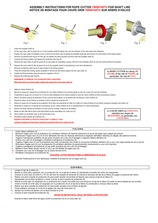
  • 1. ASSEMBLY INSTRUCTIONS FOR ROPE CUTTER TWINFAST® FOR SHAFT LINE NOTICE DE MONTAGE POUR COUPE ORIN TWINFAST® SUR ARBRE D’HELICE Fig.1 Fig. 2 Fig. 3 Fig. 4  Clean the propeller shaft (3).  Fit the rope cutter, with its guard (5) on, to the propeller shaft (3) taking care over the direction of the rope cutter (see diagrams).  Position the rope cutter (2) between 6 and 10 mm from the stern tube (4) taking the propeller shaft slip into account (3) (connected to the engine power).  Remove a protective split ring (5) so that you can tighten the fixing screw(s) and thus mark the propeller shaft (3).  Unscrew the fixing screw(s) and replace the protective split ring (5).  Remove the rope cutter (2) with its guard (5) on and make an indentation (using a drill bit) on the propeller shaft (3) over the mark(s) left by the screw(s).  Replace the razor shaft (2) with its guard (5) on to the propeller shaft (3) repositioning it over the indentation(s).  Remove a protective split ring (5) to gain access to the fixing screw(s).  Place the screws with locking system (supplied in the kit) into the hole(s) tapped into the rope cutter (2).  Tighten the fixing screw(s) using the spanner supplied in the kit.  Replace the protective split ring (5). REMEMBER TO REMOVE THE GUARD BEFORE LAUNCHING When the boat is out of the water, replace the guard (5) on the rope cutter (2) 1. Nettoyer l’arbre d’hélice (3). 2. Monter le coupe orin, équipé de sa protection (5), sur l’arbre d’hélice (3) en prenant garde au sens du coupe orin (voir les schémas). 3. Positionner le coupe orin (2) entre 6 et 10 mm du tube d’étambot (4) en tenant compte du recul de l’arbre d’hélice (3) (lié à la puissance moteur). 4. Retirer une demi-coquille de protection (5) pour pouvoir serrer la(les) vis de fixation afin de marquer l’arbre d’hélice (3). 5. Desserrer la(les) vis de fixation et remettre la demi-coquille de protection (5). 6. Retirer le coupe orin (2) équipé de sa protection (5) et faire une empreinte (à l’aide d’un forêt) sur l’arbre d’hélice (3) sur la(les) marque(s) laissée(s) par la(les) vis. 7. Remonter le coupe orin (2) équipé de sa protection (5) sur l’arbre d’hélice (3) en le repositionnant sur l’(les) empreinte(s). 8. Retirer une demi-coquille de protection (5) pour pouvoir accéder à la(aux) vis de fixation. 9. Mettre du frein filet (fourni dans le kit) dans le(les) trou(s) taraudée(s) du coupe orin (2). 10. Serrer la(les) vis de fixation avec la clé fournie dans le kit. 11. Remettre la demi-coquille de protection (5). PENSER A RETIRER LA PROTECTION AVANT LA MISE A L’EAU. Lorsque le bateau et hors d’eau, remettre la protection (5) sur le coupe orin (2). As ROPE CUTTER are sharp, BE AWARE of the risk of INJURY, in particular, the risk of CUTS Le COUPE ORIN est COUPANT, attention aux risques de BLESSURES, en particulier aux COUPURES ESPAÑOL  Limpiar el eje de la hélice (3)  Montar el corta cabo, equipado con su protección (5), en el eje de la hélice (3) atendiendo al sentido del corte (ver esquemas)  Colocar el corta cabo (2) entre 6 y 10 mm del tubo de codaste (4) teniendo en cuenta el retroceso del eje de la hélice (3) (según la potencia del motor)  Retirar una semi-coquilla de protección (5) para poder apretar los tornillos de fijación para marcar el eje de la hélice (3)  Dessapretar los tornillos de fijación y volver a poner la semi-coquilla de protección (5)  Retirar el corta cabo (2) equipado con su protección (5) y hacer una señal (con una broca) en el eje de la hélice (3) sobre la marca dejada por los tornillos  Volver a montar el corta cabo (2) equipado con su protección (5) en el eje de la hélice (3) volviéndolo a colocar sobre la señal  Retirar una semi-coquilla de protección (5) para poder acceder a los tornillos de fijación  Poner adhesivo (incluido en el kit) en el agujero de roca del corta cabo (2)  Apretar los tornillos de fijación con la llave incluida en el kit  Colocar la semi-coquilla de protección (5) ANTES DE METER EN EL AGUA, RETIRAR LA PROTECCIÓN Cuando el barco esté fuera del agua, poner la protección (5) en el corta cabo (2) I TALI AN O 1. Pulire l'albero dell'elica (3). 2. Montare il taglia cavo, con la protezione (5), sull'albero dell'elica (3) facendo attenzione al senso del taglia cavo (vedere gli schemi). 3. Posizionare il taglia cavo (2) a 6-10 mm dall'anello del tubo (4), facendo attenzione al regresso dell'albero dell'elica (3) (legato alla potenza motore). 4. Togliere il semiguscio protettivo (5) per poter chiudere una o più viti di fissaggio e segnare l'albero dell'elica (3). 5. Svitare una o più viti di fissaggio e rimettere il semiguscio di protezione (5). 6. Togliere il taglia cavo (2) con la protezione (5) e fare un'impronta (con l'aiuto di una punta) sull'albero dell'elica (3) su uno o più segni lasciati da una o più viti. 7. Rimontare il taglia cavo (2) con la protezione (5) sull'albero dell'elica (3) posizionandolo nuovamente su una o più impronte. 8. Togliere il semiguscio di protezione (5) per poter accedere ad una o più viti di fissaggio. 9. Mettere il freno filetto (fornito nel kit) in uno o più fori filettati del taglia cavo (2). 10. Chiudere una o più viti di fissaggio con la chiave fornita nel kit. 11. Rimettere il semiguscio di protezione (5). TOGLIERE LA PROTEZIONE PRIMA DI IMMERGERE IN ACQUA. Quando l'imbarcazione è fuori dall'acqua, rimettere la protezione (5) sul taglia cavo (2).