SlideShare une entreprise Scribd logo
1  sur  17
Télécharger pour lire hors ligne
610-917-0992 Fax: + 44 (0)1457-874-468
O & M Manual
E12-15
High Level NH3 Gas Transmiter
Home Office European Office
Analytical Technology, Inc. ATI (UK) Limited
6 Iron Bridge Drive Unit 1 & 2 Gatehead Business Park
Collegeville, PA 19426 Delph New Road, Delph
Phone: 800-959-0299 Saddleworth OL3 5DE
610-917-0991 Phone: +44 (0)1457-873-318
Fax: 610-917-0992 Fax: + 44 (0)1457-874-468
Email: sales@analyticaltechnology.com Email: sales@atiuk.com
Web: www.Analyticaltechnology.com
E12-15 IR Ammonia Transmitter
O & M Manual
4/16 - 2 -
TABLE OF CONTENTS
TABLE OF FIGURES ................................................................................................................ 2
SPECIFICATIONS..................................................................................................................... 3
INTRODUCTION ....................................................................................................................... 4
Features.....................................................................................................................................................4
MEASUREMENT PRINCIPLE................................................................................................... 5
INSTALLATION......................................................................................................................... 6
Warm-up..................................................................................................................................................12
Normal Operation ....................................................................................................................................12
Calibration................................................................................................................................................13
MAINTENANCE .......................................................................................................................14
SPARE PARTS LIST................................................................................................................15
TABLE OF FIGURES
FIGURE 1 - SENSOR DIMENSIONAL / CONNECTION DIAGRAM............................................................7
FIGURE 2 - SENSOR DIMENSIONAL DRAWING - FLOWCELL TYPE .....................................................8
FIGURE 3 - TYPICAL WIRING DIAGRAM E12-15 TO B14 RECEIVER .....................................................9
FIGURE 4 - TYP. DIAGRAM E12-15 TO 24V UNIVERSAL P/S TO B14 RECEIVER...............................10
FIGURE 5 - E12-15 W/12V TO 24V CONVERTER AND BATTERY BACKUP .........................................11
E12-15 IR Ammonia Transmitter
O & M Manual
4/16 - 3 -
SPECIFICATIONS
Detection Method: Diffusion
Optional sample draw
Output (analog): 4-20 mA (Source type), max. 1000 Ohm load at 24 VDC supply voltage
Response Time: T50 < 15 seconds
T90 < 30 seconds
Construction: Sensor housing is stainless steel. (SEC 5000)
Class 1, Division 1, Groups B, C and D
Ingress rating: NEMA 4X (IP66)
RFI/EMI Protection: Tested to operate correctly in the presence of a 5 watt radio operated
within 3 feet
Accuracy: +/- 3% LFL, 0 to 50% of full scale
+/- 5% LFL, 51 to 100% of full scale
Operating Temp. -40 to +70C at 0 to 99% RH (non-condensing)
Operating Voltage: 18 – 32 VDC
Power Consumption: Maximum 5.1 W
Current Draw: Average: 210 mA at 24 VDC
Peak: 400 mA
E12-15 IR Ammonia Transmitter
O & M Manual
4/16 - 4 -
INTRODUCTION
The E12-15 Infrared gas transmitter is a microprocessor based intelligent gas sensor that
continuously monitors ammonia gas in the % level up to the Lower Explosive Limit (LEL). It is ideally
suited for use in harsh environments and where the cost of required maintenance for conventional
catalytic sensors is prohibitive. The Infrared gas sensor will perform reliably in the presence of silicone
and other catalytic poisoning agents and can also operate in oxygen free environments or where high
background gas levels are present. There are no known poisons that affect this technology.
The E12-15 is a stand-alone device providing a continuous 4 to 20 mA output.
Features
 Requires no routine calibration to ensure proper operation.
 Continuous self-test automatically indicates a fault, with fail to safe operation.
 A multi-layered filtering system protects optics from dirt and water ingress.
 Straight optical path eliminates the need for reflective surfaces, such as mirrors or beam splitters.
 Performs well in the presence of high concentrations or constant background levels of hydrocarbons
and in oxygen depleted atmospheres.
 Immune to poisoning and etching.
 Standard 4 to 20 mA output (current source)
 Explosion proof housing designed for harsh environments.
 Smart Calibration AutoAC circuit.
E12-15 IR Ammonia Transmitter
O & M Manual
4/16 - 5 -
MEASUREMENT PRINCIPLE
The E12-15 gas transmitter uses infrared absorption technology for detecting Ammonia gas.
Gases absorb infrared light only at certain wavelengths. The concentration of a gas can be measured by
the difference of two channels (wavelengths), a reference and a measurement channel. The E12-15 uses
a collimated infrared light source that passes through a waveguide. At the end of the waveguide is a dual
channel receiver. The dual channel receiver measures the intensity of two specific wavelengths, one at
an absorption wavelength and another outside of the absorption wavelength. The gas concentration is
determined by a comparison of these two values.
Infrared Absorption Spectrum for Methane
The dual channel receiver is a single wafer, double filtered, dual receiver with an internal optical
barrier. The elements are perfectly matched resulting in overall stability and superior performance
throughout the entire temperature range. Using a dual channel receiver there is no need to use any
special lenses or beam splitters to achieve the different measurement bands.
Transmittance
Wavelength
100%
0%
Absorption
Band
Reference
Band
Dual Channel
Receiver
Infrared Light
Source
Waveguide
Window
Window
Waveguide
Collar
Wiring
Connections
Hydrophobic Filter
E12-15 IR Ammonia Transmitter
O & M Manual
4/16 - 6 -
INSTALLATION
The first step in the installation process is to establish a mounting location for the transmitter.
Select a location that is typical of the atmosphere to be monitored or close to the anticipated source of a
dangerous gas.
It is very important that the E12-15 be properly located to enable it to provide maximum
protection. The most effective number and placement of sensors vary depending on the conditions of the
application. When determining where to locate sensors the following factors should be considered.
 What are the characteristics of the gas that is to be detected? Is it lighter or heavier than air? If it is
lighter than air the sensor should be placed above the potential gas leak. Place the sensor close to
the floor for gases that are heavier than air or for vapors resulting from flammable liquid spills. Note
that air currents can cause a gas that is heavier than air to rise. In addition, if the temperature of the
gas is hotter than ambient air or mixed with gases that are lighter than air, it could also rise.
 How rapidly will the gas diffuse into the ambient air? Select a location for the sensor that is close to
the anticipated source of a gas leak.
 Wind or ventilation characteristics of the immediate area must also be considered. Movement of air
may cause gas to accumulate more heavily in one area than in another. The transmitter should be
placed in the areas where the most concentrated accumulation of gas is anticipated. For outdoor
applications with strong wind conditions, it may require the sensors to be mounted closer together
and on the down wind side, to the anticipated area of a gas leak. Also take into consideration for
indoor applications, the fact that many ventilation systems do not operate continuously.
 The sensor should be accessible for maintenance.
 Excessive heat or vibration can cause premature failure of any electronic device and should be
avoided if possible.
 Follow all national and local installation codes and practices.
The transmitter has a ¾” NPT threaded connector for mounting to a junction box. ATI can
provide a junction box with terminals for this purpose.
A user-supplied junction box can be used providing it has the appropriate sized NPT conduit
entries. The junction box must be suitable for use in the application and location in which it is being
installed. After the device has been installed, a calibration is required. Refer to the Calibration section of
this manual.
E12-15 IR Ammonia Transmitter
O & M Manual
4/16 - 7 -
Figure 1 - Sensor Dimensional / Connection Diagram
E12-15 IR Ammonia Transmitter
O & M Manual
4/16 - 8 -
1/8-27 NPT
2 MORE PORTS
LOCATED 180°
FROM THESE
3/4-14 NPT
7.00
6.20
2.72
.875
3.625
Figure 2 - Sensor Dimensional Drawing - Flowcell Type
E12-15 IR Ammonia Transmitter
O & M Manual
4/16 - 9 -
Figure 3 - Typical Wiring Diagram E12-15 to B14 Receiver
E12-15 IR Ammonia Transmitter
O & M Manual
4/16 - 10 -
Figure 4 - Typ. Diagram E12-15 to 24V Universal P/S to B14 Receiver
E12-15 IR Ammonia Transmitter
O & M Manual
4/16 - 11 -
Figure 5 - E12-15 w/12V to 24V Converter and Battery Backup
E12-15 IR Ammonia Transmitter
O & M Manual
4/16 - 12 -
Warm-up
When power is applied to the transmitter, it enters a one (1) minute warm-up mode. The output
current will be 0.8 mA during the warm up time period. At the end of the warm-up period with no faults
present, the transmitter automatically enters the normal operating mode (4 mA). If a fault is present after
warm-up, the transmitter current output will indicate a fault. See the following chart for fault code status.
Normal Operation
In the normal operating mode, the 4 to 20 mA signal levels correspond to the detected gas
concentration. The transmitter continuously checks for system faults or initiation of calibration and
automatically changes to the appropriate mode.
The 4 to 20 mA output of the E12-15 is a non-isolated current source.
Current Output and Corresponding Status
Current Output Status.
0-20 mA Normal measuring mode
0.6 mA Unit Fault
0.2 mA Reference channel fault
0.8 mA Unit warm up
1.0 mA Optics fault
1.2 mA Zero drift fault
1.6 mA Calibration fault
2.6 mA Analytical channel fault
2.0 mA Unit spanning
2.2 mA Unit zeroing
4.0 mA Zero gas level (0% LEL)
20 mA Full scale (100% LEL)
20.1- 23 mA Over-range (> 100% LEL)
E12-15 IR Ammonia Transmitter
O & M Manual
4/16 - 13 -
Calibration
The E12-15 is factory calibrated for zero and span. Unlike catalytic sensors it does not require
routine span gas calibration to ensure proper operation.
The unit must be spanned with cal gas only one time with the target gas. Typically this is done at
the factory, but it is possible to field span the device by connecting the unit to a computer and using a
software package provided by ATI. Please contact the factory for further details.
A typical field calibration only requires the use of zero air (or 99.99% nitrogen). If the sensor is
located in an area that is known to be free of ammonia then ambient air can be used as a zero reference.
If zero air is used for the calibration, there is a fitting on the bottom of the sensor for a 1/8” ID tubing
connection.
Before beginning calibration, use the Insulation Tube to cover outer cylinder holes and connect a
clean air source to the sensor’s calibration port for a minimum of 3 minutes. To enter into the calibration
mode, the calibration wire must be connected to common of the power supply (touch the white wire to the
black wire) for ten (10) seconds. Upon release, the sensor will automatically enter the zero calibration
routine. The electronics will automatically adjust the sensor’s signal to the new zero reference level.
During the zero calibration routine, the current output of the E12-15 will go to 2.2 mA. Although this can
be accomplished manually, installation of a switch (contact closure) can accomplish the zeroing
procedure. It is recommended that this switch be a momentary type switch to prevent it from
inadvertently being left in the calibrate position. If after 20 seconds the calibration lead has not been
removed from common, the transmitter will ignore the signal and continue operation as normal.
E12-15 IR Ammonia Transmitter
O & M Manual
4/16 - 14 -
MAINTENANCE
The E12-15 transmitter is continuously monitoring for gas concentrations and faults. If an optical
fault is indicated, first try to calibrate the device. If calibration does not correct the fault condition, try to
clean the device. The outer barrel (tube with two sets of holes) can be removed (unscrewed) to inspect
the cleanliness of the hydrophobic filter. The hydrophobic filter is a Teflon coated stainless steel mesh
that keeps moisture out of the optical path. A setscrew holds the filter to the housing. Once the
hydrophobic filter is removed, the internal waveguide tube should be inspected for cleanliness. The
waveguide and waveguide collar can be removed by inserting rigid tools such as Allen wrenches into one
hole of the waveguide and one hole of the collar. Turning the two tools in opposite directions will loosen
the waveguide, allowing the collar to be screwed down on to the waveguide until it can be removed from
the housing. This will allow the windows of the sensor to be cleaned.
Isopropyl alcohol and cotton tipped swab will provide the best results to clean the windows. Wipe
any residue or film left by the alcohol on the windows with a clean dry cotton swab. The internal electro
polished wave-guide tube can be cleaned the same way. Be careful not to leave any particles of the
cleaning swab in the waveguide. The waveguide holes can collect pieces of the cleaning swab. After
reassembling the unit (the waveguide and collar should be very tight to both ends of the housing after
installation. Once the unit is completely reassembled and power is reapplied, the transmitter must be
calibrated. Refer to the calibration section of this manual.
E12-15 IR Ammonia Transmitter
O & M Manual
4/16 - 15 -
SPARE PARTS LIST
Part Number Description
60-0059 Complete IR LEL Gas Transmitter
03-0182 Junction Box Assembly
Replacement Hydrophobic Filter
PC IR Link Kit
PRODUCT WARRANTY
Analytical Technology, Inc. (Manufacturer) warrants to the Customer that if any part(s) of the
Manufacturer's products proves to be defective in materials or workmanship within the earlier of 18
months of the date of shipment or 12 months of the date of start-up, such defective parts will be repaired
or replaced free of charge. Inspection and repairs to products thought to be defective within the warranty
period will be completed at the Manufacturer's facilities in Collegeville, PA. Products on which warranty
repairs are required shall be shipped freight prepaid to the Manufacturer. The product(s) will be returned
freight prepaid and allowed if it is determined by the manufacturer that the part(s) failed due to defective
materials or workmanship.
This warranty does not cover consumable items, batteries, or wear items subject to periodic
replacement including lamps and fuses.
Gas sensors, except oxygen sensors, are covered by this warranty, but are subject to inspection
for evidence of extended exposure to excessive gas concentrations. Should inspection indicate that
sensors have been expended rather than failed prematurely, the warranty shall not apply.
The Manufacturer assumes no liability for consequential damages of any kind, and the buyer by
acceptance of this equipment will assume all liability for the consequences of its use or misuse by the
Customer, his employees, or others. A defect within the meaning of this warranty is any part of any piece
of a Manufacturer's product which shall, when such part is capable of being renewed, repaired, or
replaced, operate to condemn such piece of equipment.
This warranty is in lieu of all other warranties (including without limiting the generality of the
foregoing warranties of merchantability and fitness for a particular purpose), guarantees, obligations or
liabilities expressed or implied by the Manufacturer or its representatives and by statute or rule of law.
This warranty is void if the Manufacturer's product(s) has been subject to misuse or abuse, or has
not been operated or stored in accordance with instructions or if the serial number has been removed.
Analytical Technology, Inc. makes no other warranty expressed or implied except as stated
above.
WATER QUALITY MONITORS
Dissolved Oxygen
Free Chlorine
Combined Chlorine
Total Chlorine
Residual Chlorine Dioxide
Potassium Permanganate
Dissolved Ozone
pH/ORP
Conductivity
Hydrogen Peroxide
Peracetic Acid
Dissolved Sulfide
Residual Sulfite
Fluoride
Dissolved Ammonia
Turbidity
Suspended Solids
Sludge Blanket Level
MetriNet Distribution Monitor
GAS DETECTION PRODUCTS
NH3 Ammonia
CO Carbon Monoxide
H2 Hydrogen
NO Nitric Oxide
O2 Oxygen
CO Cl2 Phosgene
Br2 Bromine
Cl2 Chlorine
ClO2 Chlorine Dioxide
F2 Fluorine
I2 Iodine
HX Acid Gases
C2H4O Ethylene Oxide
C2H6O Alcohol
O3 Ozone
CH4 Methane
(Combustible Gas)
H2O2 Hydrogen Peroxide
HCl Hydrogen Chloride
HCN Hydrogen Cyanide
HF Hydrogen Fluoride
H2S Hydrogen Sulfide
NO2 Nitrogen Dioxide
NOx Oxides of Nitrogen
SO2 Sulfur Dioxide
H2Se Hydrogen Selenide
B2H6 Diborane
GeH4 Germane
AsH3 Arsine
PH3 Phosphine
SiH4 Silane
HCHO Formaldehyde
C2H4O3 Peracetic Acid
DMA Dimethylamine

Contenu connexe

Similaire à E12-15-IR-High-Level-Ammonia-Gas-Transmitter O&M.pdf

Vibrating Fork Level Limit Switch for Solids.pdf
Vibrating Fork Level Limit Switch for Solids.pdfVibrating Fork Level Limit Switch for Solids.pdf
Vibrating Fork Level Limit Switch for Solids.pdf
Trumen Technologies Pvt. Ltd. India
 
CO/CO2 level indicator Seminar
CO/CO2 level indicator SeminarCO/CO2 level indicator Seminar
CO/CO2 level indicator Seminar
Ravi Teja S V
 
Vibrating Rod Level Switch for Solids.pdf
Vibrating Rod Level Switch for Solids.pdfVibrating Rod Level Switch for Solids.pdf
Vibrating Rod Level Switch for Solids.pdf
Trumen Technologies Pvt. Ltd. India
 

Similaire à E12-15-IR-High-Level-Ammonia-Gas-Transmitter O&M.pdf (20)

KwikSense Smart Digital Gas Transmitter
KwikSense Smart Digital Gas TransmitterKwikSense Smart Digital Gas Transmitter
KwikSense Smart Digital Gas Transmitter
 
EL300 multi channel water controller-tethys datasheet
EL300 multi channel water controller-tethys datasheetEL300 multi channel water controller-tethys datasheet
EL300 multi channel water controller-tethys datasheet
 
Drager Polytron 5700 Fixed Gas Detector - Spec Sheet
Drager Polytron 5700 Fixed Gas Detector - Spec SheetDrager Polytron 5700 Fixed Gas Detector - Spec Sheet
Drager Polytron 5700 Fixed Gas Detector - Spec Sheet
 
Drager Polytron 5720 Fixed Gas Detector - Spec Sheet
Drager Polytron 5720 Fixed Gas Detector - Spec SheetDrager Polytron 5720 Fixed Gas Detector - Spec Sheet
Drager Polytron 5720 Fixed Gas Detector - Spec Sheet
 
Vibrating Fork Level Limit Switch for Solids.pdf
Vibrating Fork Level Limit Switch for Solids.pdfVibrating Fork Level Limit Switch for Solids.pdf
Vibrating Fork Level Limit Switch for Solids.pdf
 
Sensepoint_Pro_pdf.pdf
Sensepoint_Pro_pdf.pdfSensepoint_Pro_pdf.pdf
Sensepoint_Pro_pdf.pdf
 
Ultrasonic level meter
Ultrasonic level meterUltrasonic level meter
Ultrasonic level meter
 
Vortex flow meter manual
Vortex flow meter manualVortex flow meter manual
Vortex flow meter manual
 
CO/CO2 level indicator Seminar
CO/CO2 level indicator SeminarCO/CO2 level indicator Seminar
CO/CO2 level indicator Seminar
 
Ds g-700
Ds g-700Ds g-700
Ds g-700
 
Executive summary
Executive summaryExecutive summary
Executive summary
 
13.Safety & navigation
13.Safety & navigation13.Safety & navigation
13.Safety & navigation
 
Vibrating Rod Point Level Switch for Solids India
Vibrating Rod Point Level Switch for Solids IndiaVibrating Rod Point Level Switch for Solids India
Vibrating Rod Point Level Switch for Solids India
 
Vibrating Rod Level Switch for Solids.pdf
Vibrating Rod Level Switch for Solids.pdfVibrating Rod Level Switch for Solids.pdf
Vibrating Rod Level Switch for Solids.pdf
 
Embedding Realtime Multilevel Gas Leakage Control System
Embedding Realtime Multilevel Gas Leakage Control SystemEmbedding Realtime Multilevel Gas Leakage Control System
Embedding Realtime Multilevel Gas Leakage Control System
 
Manual ponte rolante_im-pn-tx103-a01-en
Manual ponte rolante_im-pn-tx103-a01-enManual ponte rolante_im-pn-tx103-a01-en
Manual ponte rolante_im-pn-tx103-a01-en
 
RIVPF_GB_LOCAL
RIVPF_GB_LOCALRIVPF_GB_LOCAL
RIVPF_GB_LOCAL
 
80G FM Radar Level Meter Product Manual
80G FM Radar Level Meter Product Manual80G FM Radar Level Meter Product Manual
80G FM Radar Level Meter Product Manual
 
Megger Cable Fault Locators - Power Cable Fault Locators, Van mountable Solut...
Megger Cable Fault Locators - Power Cable Fault Locators, Van mountable Solut...Megger Cable Fault Locators - Power Cable Fault Locators, Van mountable Solut...
Megger Cable Fault Locators - Power Cable Fault Locators, Van mountable Solut...
 
Zigbee based intelligent helemet for coal miners ppt
Zigbee based intelligent helemet for coal miners pptZigbee based intelligent helemet for coal miners ppt
Zigbee based intelligent helemet for coal miners ppt
 

Plus de ENVIMART

Plus de ENVIMART (20)

Zinc Continuous Analysis from SEIBOLD-Wasser.pdf
Zinc Continuous Analysis from SEIBOLD-Wasser.pdfZinc Continuous Analysis from SEIBOLD-Wasser.pdf
Zinc Continuous Analysis from SEIBOLD-Wasser.pdf
 
Nickel Continuous Analysis from SEIBOLD-Wasser.pdf
Nickel Continuous Analysis from SEIBOLD-Wasser.pdfNickel Continuous Analysis from SEIBOLD-Wasser.pdf
Nickel Continuous Analysis from SEIBOLD-Wasser.pdf
 
Manganese Continuous Analysis from SEIBOLD-Wasser.pdf
Manganese Continuous Analysis from SEIBOLD-Wasser.pdfManganese Continuous Analysis from SEIBOLD-Wasser.pdf
Manganese Continuous Analysis from SEIBOLD-Wasser.pdf
 
Lead Continuous Analysis from SEIBOLD-Wasser.pdf
Lead Continuous Analysis from SEIBOLD-Wasser.pdfLead Continuous Analysis from SEIBOLD-Wasser.pdf
Lead Continuous Analysis from SEIBOLD-Wasser.pdf
 
Iron Manganese Continuous Analysis from SEIBOLD-Wasser.pdf
Iron Manganese Continuous Analysis from SEIBOLD-Wasser.pdfIron Manganese Continuous Analysis from SEIBOLD-Wasser.pdf
Iron Manganese Continuous Analysis from SEIBOLD-Wasser.pdf
 
Iron Continuous Analysis from SEIBOLD-Wasser.pdf
Iron Continuous Analysis from SEIBOLD-Wasser.pdfIron Continuous Analysis from SEIBOLD-Wasser.pdf
Iron Continuous Analysis from SEIBOLD-Wasser.pdf
 
Chromium Continuous Analysis from SEIBOLD-Wasser.pdf
Chromium Continuous Analysis from SEIBOLD-Wasser.pdfChromium Continuous Analysis from SEIBOLD-Wasser.pdf
Chromium Continuous Analysis from SEIBOLD-Wasser.pdf
 
Copper Zinc Continuous Analysis from SEIBOLD-Wasser.pdf
Copper Zinc Continuous Analysis from SEIBOLD-Wasser.pdfCopper Zinc Continuous Analysis from SEIBOLD-Wasser.pdf
Copper Zinc Continuous Analysis from SEIBOLD-Wasser.pdf
 
Copper Nickel Continuous Analysis from SEIBOLD-Wasser.pdf
Copper Nickel Continuous Analysis from SEIBOLD-Wasser.pdfCopper Nickel Continuous Analysis from SEIBOLD-Wasser.pdf
Copper Nickel Continuous Analysis from SEIBOLD-Wasser.pdf
 
Copper Continuous Analysis from SEIBOLD-Wasser.pdf
Copper Continuous Analysis from SEIBOLD-Wasser.pdfCopper Continuous Analysis from SEIBOLD-Wasser.pdf
Copper Continuous Analysis from SEIBOLD-Wasser.pdf
 
Cobalt Continuous Analysis from SEIBOLD-Wasser.pdf
Cobalt Continuous Analysis from SEIBOLD-Wasser.pdfCobalt Continuous Analysis from SEIBOLD-Wasser.pdf
Cobalt Continuous Analysis from SEIBOLD-Wasser.pdf
 
Cadmium Continuous Analysis from SEIBOLD-Wasser.pdf
Cadmium Continuous Analysis from SEIBOLD-Wasser.pdfCadmium Continuous Analysis from SEIBOLD-Wasser.pdf
Cadmium Continuous Analysis from SEIBOLD-Wasser.pdf
 
Arsenic Continuous Analysis from SEIBOLD-Wasser.pdf
Arsenic Continuous Analysis from SEIBOLD-Wasser.pdfArsenic Continuous Analysis from SEIBOLD-Wasser.pdf
Arsenic Continuous Analysis from SEIBOLD-Wasser.pdf
 
Aluminium Continuous Analysis from SEIBOLD-Wasser.pdf
Aluminium Continuous Analysis from SEIBOLD-Wasser.pdfAluminium Continuous Analysis from SEIBOLD-Wasser.pdf
Aluminium Continuous Analysis from SEIBOLD-Wasser.pdf
 
ATIs-B12-2-Wire-Gas-Transmitter-Product-Literature.pdf
ATIs-B12-2-Wire-Gas-Transmitter-Product-Literature.pdfATIs-B12-2-Wire-Gas-Transmitter-Product-Literature.pdf
ATIs-B12-2-Wire-Gas-Transmitter-Product-Literature.pdf
 
ATIs-B12-2-Wire-Gas-Transmitter-Support-Drawings.pdf
ATIs-B12-2-Wire-Gas-Transmitter-Support-Drawings.pdfATIs-B12-2-Wire-Gas-Transmitter-Support-Drawings.pdf
ATIs-B12-2-Wire-Gas-Transmitter-Support-Drawings.pdf
 
ATIs-B12-Wet-Gas-Detector-Product-Literature.pdf
ATIs-B12-Wet-Gas-Detector-Product-Literature.pdfATIs-B12-Wet-Gas-Detector-Product-Literature.pdf
ATIs-B12-Wet-Gas-Detector-Product-Literature.pdf
 
ATIs-B12-Wet-Gas-Detector-Support-Drawings.pdf
ATIs-B12-Wet-Gas-Detector-Support-Drawings.pdfATIs-B12-Wet-Gas-Detector-Support-Drawings.pdf
ATIs-B12-Wet-Gas-Detector-Support-Drawings.pdf
 
ATIs-B14-Gas-Alarm-Module-Product-Literature.pdf
ATIs-B14-Gas-Alarm-Module-Product-Literature.pdfATIs-B14-Gas-Alarm-Module-Product-Literature.pdf
ATIs-B14-Gas-Alarm-Module-Product-Literature.pdf
 
B12-2-Wire-Gas-Transmitter.pdf
B12-2-Wire-Gas-Transmitter.pdfB12-2-Wire-Gas-Transmitter.pdf
B12-2-Wire-Gas-Transmitter.pdf
 

Dernier

E Waste Management
E Waste ManagementE Waste Management
E Waste Management
Dr. Salem Baidas
 
young Whatsapp Call Girls in Delhi Cantt🔝 9953056974 🔝 escort service
young Whatsapp Call Girls in Delhi Cantt🔝 9953056974 🔝 escort serviceyoung Whatsapp Call Girls in Delhi Cantt🔝 9953056974 🔝 escort service
young Whatsapp Call Girls in Delhi Cantt🔝 9953056974 🔝 escort service
9953056974 Low Rate Call Girls In Saket, Delhi NCR
 
Training Of Trainers FAI Eng. Basel Tilapia Welfare.pdf
Training Of Trainers FAI Eng. Basel Tilapia Welfare.pdfTraining Of Trainers FAI Eng. Basel Tilapia Welfare.pdf
Training Of Trainers FAI Eng. Basel Tilapia Welfare.pdf
Basel Ahmed
 
Contact Number Call Girls Service In Goa 9316020077 Goa Call Girls Service
Contact Number Call Girls Service In Goa  9316020077 Goa  Call Girls ServiceContact Number Call Girls Service In Goa  9316020077 Goa  Call Girls Service
Contact Number Call Girls Service In Goa 9316020077 Goa Call Girls Service
sexy call girls service in goa
 

Dernier (20)

Booking open Available Pune Call Girls Yewalewadi 6297143586 Call Hot Indian...
Booking open Available Pune Call Girls Yewalewadi  6297143586 Call Hot Indian...Booking open Available Pune Call Girls Yewalewadi  6297143586 Call Hot Indian...
Booking open Available Pune Call Girls Yewalewadi 6297143586 Call Hot Indian...
 
Proposed Amendments to Chapter 15, Article X: Wetland Conservation Areas
Proposed Amendments to Chapter 15, Article X: Wetland Conservation AreasProposed Amendments to Chapter 15, Article X: Wetland Conservation Areas
Proposed Amendments to Chapter 15, Article X: Wetland Conservation Areas
 
E Waste Management
E Waste ManagementE Waste Management
E Waste Management
 
Alandi Road ( Call Girls ) Pune 6297143586 Hot Model With Sexy Bhabi Ready ...
Alandi Road ( Call Girls ) Pune  6297143586  Hot Model With Sexy Bhabi Ready ...Alandi Road ( Call Girls ) Pune  6297143586  Hot Model With Sexy Bhabi Ready ...
Alandi Road ( Call Girls ) Pune 6297143586 Hot Model With Sexy Bhabi Ready ...
 
young Whatsapp Call Girls in Delhi Cantt🔝 9953056974 🔝 escort service
young Whatsapp Call Girls in Delhi Cantt🔝 9953056974 🔝 escort serviceyoung Whatsapp Call Girls in Delhi Cantt🔝 9953056974 🔝 escort service
young Whatsapp Call Girls in Delhi Cantt🔝 9953056974 🔝 escort service
 
Booking open Available Pune Call Girls Budhwar Peth 6297143586 Call Hot Indi...
Booking open Available Pune Call Girls Budhwar Peth  6297143586 Call Hot Indi...Booking open Available Pune Call Girls Budhwar Peth  6297143586 Call Hot Indi...
Booking open Available Pune Call Girls Budhwar Peth 6297143586 Call Hot Indi...
 
Call Girls Magarpatta Call Me 7737669865 Budget Friendly No Advance Booking
Call Girls Magarpatta Call Me 7737669865 Budget Friendly No Advance BookingCall Girls Magarpatta Call Me 7737669865 Budget Friendly No Advance Booking
Call Girls Magarpatta Call Me 7737669865 Budget Friendly No Advance Booking
 
VIP Model Call Girls Bhosari ( Pune ) Call ON 8005736733 Starting From 5K to ...
VIP Model Call Girls Bhosari ( Pune ) Call ON 8005736733 Starting From 5K to ...VIP Model Call Girls Bhosari ( Pune ) Call ON 8005736733 Starting From 5K to ...
VIP Model Call Girls Bhosari ( Pune ) Call ON 8005736733 Starting From 5K to ...
 
Verified Trusted Kalyani Nagar Call Girls 8005736733 𝐈𝐍𝐃𝐄𝐏𝐄𝐍𝐃𝐄𝐍𝐓 Call 𝐆𝐈𝐑𝐋 𝐕...
Verified Trusted Kalyani Nagar Call Girls  8005736733 𝐈𝐍𝐃𝐄𝐏𝐄𝐍𝐃𝐄𝐍𝐓 Call 𝐆𝐈𝐑𝐋 𝐕...Verified Trusted Kalyani Nagar Call Girls  8005736733 𝐈𝐍𝐃𝐄𝐏𝐄𝐍𝐃𝐄𝐍𝐓 Call 𝐆𝐈𝐑𝐋 𝐕...
Verified Trusted Kalyani Nagar Call Girls 8005736733 𝐈𝐍𝐃𝐄𝐏𝐄𝐍𝐃𝐄𝐍𝐓 Call 𝐆𝐈𝐑𝐋 𝐕...
 
Call Girl Nagpur Roshni Call 7001035870 Meet With Nagpur Escorts
Call Girl Nagpur Roshni Call 7001035870 Meet With Nagpur EscortsCall Girl Nagpur Roshni Call 7001035870 Meet With Nagpur Escorts
Call Girl Nagpur Roshni Call 7001035870 Meet With Nagpur Escorts
 
Call On 6297143586 Pimpri Chinchwad Call Girls In All Pune 24/7 Provide Call...
Call On 6297143586  Pimpri Chinchwad Call Girls In All Pune 24/7 Provide Call...Call On 6297143586  Pimpri Chinchwad Call Girls In All Pune 24/7 Provide Call...
Call On 6297143586 Pimpri Chinchwad Call Girls In All Pune 24/7 Provide Call...
 
DENR EPR Law Compliance Updates April 2024
DENR EPR Law Compliance Updates April 2024DENR EPR Law Compliance Updates April 2024
DENR EPR Law Compliance Updates April 2024
 
Training Of Trainers FAI Eng. Basel Tilapia Welfare.pdf
Training Of Trainers FAI Eng. Basel Tilapia Welfare.pdfTraining Of Trainers FAI Eng. Basel Tilapia Welfare.pdf
Training Of Trainers FAI Eng. Basel Tilapia Welfare.pdf
 
Call Girls Budhwar Peth Call Me 7737669865 Budget Friendly No Advance Booking
Call Girls Budhwar Peth Call Me 7737669865 Budget Friendly No Advance BookingCall Girls Budhwar Peth Call Me 7737669865 Budget Friendly No Advance Booking
Call Girls Budhwar Peth Call Me 7737669865 Budget Friendly No Advance Booking
 
Call Girls Moshi Call Me 7737669865 Budget Friendly No Advance Booking
Call Girls Moshi Call Me 7737669865 Budget Friendly No Advance BookingCall Girls Moshi Call Me 7737669865 Budget Friendly No Advance Booking
Call Girls Moshi Call Me 7737669865 Budget Friendly No Advance Booking
 
VIP Model Call Girls Viman Nagar ( Pune ) Call ON 8005736733 Starting From 5K...
VIP Model Call Girls Viman Nagar ( Pune ) Call ON 8005736733 Starting From 5K...VIP Model Call Girls Viman Nagar ( Pune ) Call ON 8005736733 Starting From 5K...
VIP Model Call Girls Viman Nagar ( Pune ) Call ON 8005736733 Starting From 5K...
 
VIP Model Call Girls Wagholi ( Pune ) Call ON 8005736733 Starting From 5K to ...
VIP Model Call Girls Wagholi ( Pune ) Call ON 8005736733 Starting From 5K to ...VIP Model Call Girls Wagholi ( Pune ) Call ON 8005736733 Starting From 5K to ...
VIP Model Call Girls Wagholi ( Pune ) Call ON 8005736733 Starting From 5K to ...
 
Contact Number Call Girls Service In Goa 9316020077 Goa Call Girls Service
Contact Number Call Girls Service In Goa  9316020077 Goa  Call Girls ServiceContact Number Call Girls Service In Goa  9316020077 Goa  Call Girls Service
Contact Number Call Girls Service In Goa 9316020077 Goa Call Girls Service
 
Get Premium Hoskote Call Girls (8005736733) 24x7 Rate 15999 with A/c Room Cas...
Get Premium Hoskote Call Girls (8005736733) 24x7 Rate 15999 with A/c Room Cas...Get Premium Hoskote Call Girls (8005736733) 24x7 Rate 15999 with A/c Room Cas...
Get Premium Hoskote Call Girls (8005736733) 24x7 Rate 15999 with A/c Room Cas...
 
CSR_Module5_Green Earth Initiative, Tree Planting Day
CSR_Module5_Green Earth Initiative, Tree Planting DayCSR_Module5_Green Earth Initiative, Tree Planting Day
CSR_Module5_Green Earth Initiative, Tree Planting Day
 

E12-15-IR-High-Level-Ammonia-Gas-Transmitter O&M.pdf

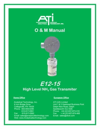
  • 1. 610-917-0992 Fax: + 44 (0)1457-874-468 O & M Manual E12-15 High Level NH3 Gas Transmiter Home Office European Office Analytical Technology, Inc. ATI (UK) Limited 6 Iron Bridge Drive Unit 1 & 2 Gatehead Business Park Collegeville, PA 19426 Delph New Road, Delph Phone: 800-959-0299 Saddleworth OL3 5DE 610-917-0991 Phone: +44 (0)1457-873-318 Fax: 610-917-0992 Fax: + 44 (0)1457-874-468 Email: sales@analyticaltechnology.com Email: sales@atiuk.com Web: www.Analyticaltechnology.com
  • 2. E12-15 IR Ammonia Transmitter O & M Manual 4/16 - 2 - TABLE OF CONTENTS TABLE OF FIGURES ................................................................................................................ 2 SPECIFICATIONS..................................................................................................................... 3 INTRODUCTION ....................................................................................................................... 4 Features.....................................................................................................................................................4 MEASUREMENT PRINCIPLE................................................................................................... 5 INSTALLATION......................................................................................................................... 6 Warm-up..................................................................................................................................................12 Normal Operation ....................................................................................................................................12 Calibration................................................................................................................................................13 MAINTENANCE .......................................................................................................................14 SPARE PARTS LIST................................................................................................................15 TABLE OF FIGURES FIGURE 1 - SENSOR DIMENSIONAL / CONNECTION DIAGRAM............................................................7 FIGURE 2 - SENSOR DIMENSIONAL DRAWING - FLOWCELL TYPE .....................................................8 FIGURE 3 - TYPICAL WIRING DIAGRAM E12-15 TO B14 RECEIVER .....................................................9 FIGURE 4 - TYP. DIAGRAM E12-15 TO 24V UNIVERSAL P/S TO B14 RECEIVER...............................10 FIGURE 5 - E12-15 W/12V TO 24V CONVERTER AND BATTERY BACKUP .........................................11
  • 3. E12-15 IR Ammonia Transmitter O & M Manual 4/16 - 3 - SPECIFICATIONS Detection Method: Diffusion Optional sample draw Output (analog): 4-20 mA (Source type), max. 1000 Ohm load at 24 VDC supply voltage Response Time: T50 < 15 seconds T90 < 30 seconds Construction: Sensor housing is stainless steel. (SEC 5000) Class 1, Division 1, Groups B, C and D Ingress rating: NEMA 4X (IP66) RFI/EMI Protection: Tested to operate correctly in the presence of a 5 watt radio operated within 3 feet Accuracy: +/- 3% LFL, 0 to 50% of full scale +/- 5% LFL, 51 to 100% of full scale Operating Temp. -40 to +70C at 0 to 99% RH (non-condensing) Operating Voltage: 18 – 32 VDC Power Consumption: Maximum 5.1 W Current Draw: Average: 210 mA at 24 VDC Peak: 400 mA
  • 4. E12-15 IR Ammonia Transmitter O & M Manual 4/16 - 4 - INTRODUCTION The E12-15 Infrared gas transmitter is a microprocessor based intelligent gas sensor that continuously monitors ammonia gas in the % level up to the Lower Explosive Limit (LEL). It is ideally suited for use in harsh environments and where the cost of required maintenance for conventional catalytic sensors is prohibitive. The Infrared gas sensor will perform reliably in the presence of silicone and other catalytic poisoning agents and can also operate in oxygen free environments or where high background gas levels are present. There are no known poisons that affect this technology. The E12-15 is a stand-alone device providing a continuous 4 to 20 mA output. Features  Requires no routine calibration to ensure proper operation.  Continuous self-test automatically indicates a fault, with fail to safe operation.  A multi-layered filtering system protects optics from dirt and water ingress.  Straight optical path eliminates the need for reflective surfaces, such as mirrors or beam splitters.  Performs well in the presence of high concentrations or constant background levels of hydrocarbons and in oxygen depleted atmospheres.  Immune to poisoning and etching.  Standard 4 to 20 mA output (current source)  Explosion proof housing designed for harsh environments.  Smart Calibration AutoAC circuit.
  • 5. E12-15 IR Ammonia Transmitter O & M Manual 4/16 - 5 - MEASUREMENT PRINCIPLE The E12-15 gas transmitter uses infrared absorption technology for detecting Ammonia gas. Gases absorb infrared light only at certain wavelengths. The concentration of a gas can be measured by the difference of two channels (wavelengths), a reference and a measurement channel. The E12-15 uses a collimated infrared light source that passes through a waveguide. At the end of the waveguide is a dual channel receiver. The dual channel receiver measures the intensity of two specific wavelengths, one at an absorption wavelength and another outside of the absorption wavelength. The gas concentration is determined by a comparison of these two values. Infrared Absorption Spectrum for Methane The dual channel receiver is a single wafer, double filtered, dual receiver with an internal optical barrier. The elements are perfectly matched resulting in overall stability and superior performance throughout the entire temperature range. Using a dual channel receiver there is no need to use any special lenses or beam splitters to achieve the different measurement bands. Transmittance Wavelength 100% 0% Absorption Band Reference Band Dual Channel Receiver Infrared Light Source Waveguide Window Window Waveguide Collar Wiring Connections Hydrophobic Filter
  • 6. E12-15 IR Ammonia Transmitter O & M Manual 4/16 - 6 - INSTALLATION The first step in the installation process is to establish a mounting location for the transmitter. Select a location that is typical of the atmosphere to be monitored or close to the anticipated source of a dangerous gas. It is very important that the E12-15 be properly located to enable it to provide maximum protection. The most effective number and placement of sensors vary depending on the conditions of the application. When determining where to locate sensors the following factors should be considered.  What are the characteristics of the gas that is to be detected? Is it lighter or heavier than air? If it is lighter than air the sensor should be placed above the potential gas leak. Place the sensor close to the floor for gases that are heavier than air or for vapors resulting from flammable liquid spills. Note that air currents can cause a gas that is heavier than air to rise. In addition, if the temperature of the gas is hotter than ambient air or mixed with gases that are lighter than air, it could also rise.  How rapidly will the gas diffuse into the ambient air? Select a location for the sensor that is close to the anticipated source of a gas leak.  Wind or ventilation characteristics of the immediate area must also be considered. Movement of air may cause gas to accumulate more heavily in one area than in another. The transmitter should be placed in the areas where the most concentrated accumulation of gas is anticipated. For outdoor applications with strong wind conditions, it may require the sensors to be mounted closer together and on the down wind side, to the anticipated area of a gas leak. Also take into consideration for indoor applications, the fact that many ventilation systems do not operate continuously.  The sensor should be accessible for maintenance.  Excessive heat or vibration can cause premature failure of any electronic device and should be avoided if possible.  Follow all national and local installation codes and practices. The transmitter has a ¾” NPT threaded connector for mounting to a junction box. ATI can provide a junction box with terminals for this purpose. A user-supplied junction box can be used providing it has the appropriate sized NPT conduit entries. The junction box must be suitable for use in the application and location in which it is being installed. After the device has been installed, a calibration is required. Refer to the Calibration section of this manual.
  • 7. E12-15 IR Ammonia Transmitter O & M Manual 4/16 - 7 - Figure 1 - Sensor Dimensional / Connection Diagram
  • 8. E12-15 IR Ammonia Transmitter O & M Manual 4/16 - 8 - 1/8-27 NPT 2 MORE PORTS LOCATED 180° FROM THESE 3/4-14 NPT 7.00 6.20 2.72 .875 3.625 Figure 2 - Sensor Dimensional Drawing - Flowcell Type
  • 9. E12-15 IR Ammonia Transmitter O & M Manual 4/16 - 9 - Figure 3 - Typical Wiring Diagram E12-15 to B14 Receiver
  • 10. E12-15 IR Ammonia Transmitter O & M Manual 4/16 - 10 - Figure 4 - Typ. Diagram E12-15 to 24V Universal P/S to B14 Receiver
  • 11. E12-15 IR Ammonia Transmitter O & M Manual 4/16 - 11 - Figure 5 - E12-15 w/12V to 24V Converter and Battery Backup
  • 12. E12-15 IR Ammonia Transmitter O & M Manual 4/16 - 12 - Warm-up When power is applied to the transmitter, it enters a one (1) minute warm-up mode. The output current will be 0.8 mA during the warm up time period. At the end of the warm-up period with no faults present, the transmitter automatically enters the normal operating mode (4 mA). If a fault is present after warm-up, the transmitter current output will indicate a fault. See the following chart for fault code status. Normal Operation In the normal operating mode, the 4 to 20 mA signal levels correspond to the detected gas concentration. The transmitter continuously checks for system faults or initiation of calibration and automatically changes to the appropriate mode. The 4 to 20 mA output of the E12-15 is a non-isolated current source. Current Output and Corresponding Status Current Output Status. 0-20 mA Normal measuring mode 0.6 mA Unit Fault 0.2 mA Reference channel fault 0.8 mA Unit warm up 1.0 mA Optics fault 1.2 mA Zero drift fault 1.6 mA Calibration fault 2.6 mA Analytical channel fault 2.0 mA Unit spanning 2.2 mA Unit zeroing 4.0 mA Zero gas level (0% LEL) 20 mA Full scale (100% LEL) 20.1- 23 mA Over-range (> 100% LEL)
  • 13. E12-15 IR Ammonia Transmitter O & M Manual 4/16 - 13 - Calibration The E12-15 is factory calibrated for zero and span. Unlike catalytic sensors it does not require routine span gas calibration to ensure proper operation. The unit must be spanned with cal gas only one time with the target gas. Typically this is done at the factory, but it is possible to field span the device by connecting the unit to a computer and using a software package provided by ATI. Please contact the factory for further details. A typical field calibration only requires the use of zero air (or 99.99% nitrogen). If the sensor is located in an area that is known to be free of ammonia then ambient air can be used as a zero reference. If zero air is used for the calibration, there is a fitting on the bottom of the sensor for a 1/8” ID tubing connection. Before beginning calibration, use the Insulation Tube to cover outer cylinder holes and connect a clean air source to the sensor’s calibration port for a minimum of 3 minutes. To enter into the calibration mode, the calibration wire must be connected to common of the power supply (touch the white wire to the black wire) for ten (10) seconds. Upon release, the sensor will automatically enter the zero calibration routine. The electronics will automatically adjust the sensor’s signal to the new zero reference level. During the zero calibration routine, the current output of the E12-15 will go to 2.2 mA. Although this can be accomplished manually, installation of a switch (contact closure) can accomplish the zeroing procedure. It is recommended that this switch be a momentary type switch to prevent it from inadvertently being left in the calibrate position. If after 20 seconds the calibration lead has not been removed from common, the transmitter will ignore the signal and continue operation as normal.
  • 14. E12-15 IR Ammonia Transmitter O & M Manual 4/16 - 14 - MAINTENANCE The E12-15 transmitter is continuously monitoring for gas concentrations and faults. If an optical fault is indicated, first try to calibrate the device. If calibration does not correct the fault condition, try to clean the device. The outer barrel (tube with two sets of holes) can be removed (unscrewed) to inspect the cleanliness of the hydrophobic filter. The hydrophobic filter is a Teflon coated stainless steel mesh that keeps moisture out of the optical path. A setscrew holds the filter to the housing. Once the hydrophobic filter is removed, the internal waveguide tube should be inspected for cleanliness. The waveguide and waveguide collar can be removed by inserting rigid tools such as Allen wrenches into one hole of the waveguide and one hole of the collar. Turning the two tools in opposite directions will loosen the waveguide, allowing the collar to be screwed down on to the waveguide until it can be removed from the housing. This will allow the windows of the sensor to be cleaned. Isopropyl alcohol and cotton tipped swab will provide the best results to clean the windows. Wipe any residue or film left by the alcohol on the windows with a clean dry cotton swab. The internal electro polished wave-guide tube can be cleaned the same way. Be careful not to leave any particles of the cleaning swab in the waveguide. The waveguide holes can collect pieces of the cleaning swab. After reassembling the unit (the waveguide and collar should be very tight to both ends of the housing after installation. Once the unit is completely reassembled and power is reapplied, the transmitter must be calibrated. Refer to the calibration section of this manual.
  • 15. E12-15 IR Ammonia Transmitter O & M Manual 4/16 - 15 - SPARE PARTS LIST Part Number Description 60-0059 Complete IR LEL Gas Transmitter 03-0182 Junction Box Assembly Replacement Hydrophobic Filter PC IR Link Kit
  • 16. PRODUCT WARRANTY Analytical Technology, Inc. (Manufacturer) warrants to the Customer that if any part(s) of the Manufacturer's products proves to be defective in materials or workmanship within the earlier of 18 months of the date of shipment or 12 months of the date of start-up, such defective parts will be repaired or replaced free of charge. Inspection and repairs to products thought to be defective within the warranty period will be completed at the Manufacturer's facilities in Collegeville, PA. Products on which warranty repairs are required shall be shipped freight prepaid to the Manufacturer. The product(s) will be returned freight prepaid and allowed if it is determined by the manufacturer that the part(s) failed due to defective materials or workmanship. This warranty does not cover consumable items, batteries, or wear items subject to periodic replacement including lamps and fuses. Gas sensors, except oxygen sensors, are covered by this warranty, but are subject to inspection for evidence of extended exposure to excessive gas concentrations. Should inspection indicate that sensors have been expended rather than failed prematurely, the warranty shall not apply. The Manufacturer assumes no liability for consequential damages of any kind, and the buyer by acceptance of this equipment will assume all liability for the consequences of its use or misuse by the Customer, his employees, or others. A defect within the meaning of this warranty is any part of any piece of a Manufacturer's product which shall, when such part is capable of being renewed, repaired, or replaced, operate to condemn such piece of equipment. This warranty is in lieu of all other warranties (including without limiting the generality of the foregoing warranties of merchantability and fitness for a particular purpose), guarantees, obligations or liabilities expressed or implied by the Manufacturer or its representatives and by statute or rule of law. This warranty is void if the Manufacturer's product(s) has been subject to misuse or abuse, or has not been operated or stored in accordance with instructions or if the serial number has been removed. Analytical Technology, Inc. makes no other warranty expressed or implied except as stated above.
  • 17. WATER QUALITY MONITORS Dissolved Oxygen Free Chlorine Combined Chlorine Total Chlorine Residual Chlorine Dioxide Potassium Permanganate Dissolved Ozone pH/ORP Conductivity Hydrogen Peroxide Peracetic Acid Dissolved Sulfide Residual Sulfite Fluoride Dissolved Ammonia Turbidity Suspended Solids Sludge Blanket Level MetriNet Distribution Monitor GAS DETECTION PRODUCTS NH3 Ammonia CO Carbon Monoxide H2 Hydrogen NO Nitric Oxide O2 Oxygen CO Cl2 Phosgene Br2 Bromine Cl2 Chlorine ClO2 Chlorine Dioxide F2 Fluorine I2 Iodine HX Acid Gases C2H4O Ethylene Oxide C2H6O Alcohol O3 Ozone CH4 Methane (Combustible Gas) H2O2 Hydrogen Peroxide HCl Hydrogen Chloride HCN Hydrogen Cyanide HF Hydrogen Fluoride H2S Hydrogen Sulfide NO2 Nitrogen Dioxide NOx Oxides of Nitrogen SO2 Sulfur Dioxide H2Se Hydrogen Selenide B2H6 Diborane GeH4 Germane AsH3 Arsine PH3 Phosphine SiH4 Silane HCHO Formaldehyde C2H4O3 Peracetic Acid DMA Dimethylamine