1. M.T.M. s.r.l.
Via La Morra, 1
12062 - Cherasco (Cn) - Italy
Tel. +39 0172 48681
Fax +39 0172 593113
http://www.brc.it/
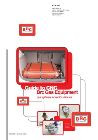
Guide to CNG
Brc Gas Equipment
gas systems for motor vehicles
UNI EN ISO
9001:2000
Certified
Company
90AV99001011 - N. 01 of 02.27.2004
2. 2 GUIDE TO CNG
1. GASEOUS FUELS Of course, they can’t be stocked intrinsic qualities, to the technologi-
neither in the open air, nor in con- cal progress, to the geographical
tainer with environmental tempera- growing of the markets and to the
ture or pressure. discover of big deposits in West
To increase its energy, with a Europe, Russia, North Africa and
same volume stocked, it’s neces- Middle East. Today, it’s the third
sary to compress or liquefy it, and world energetic source after oil and
then stock it in thermo-insulating coal: every year, we consume more
containers at a very low temperatu- than 2.400 billions cubic meters of
re (for CNG - 180 °C). it, namely the 23% of the world
Among the fuel classes, gathe- energetic request.
red according to their aggregation 1.1. COMBUSTIBLES NATU-
state in solid, liquid and gaseous RAL GAS In Italy, some big deposits have
fuels, these latter are the freest These words indicate all natural been found under the Padana Plain
from impurities, the most suitable to combustibles gases such as the alluvial layer, near Ravenna, in
supply burners, combustion cham- fossil, the marsh, the volcanic and some areas of South Italy and in
bers and furnaces, and they can the mine ones. Sicily.
easily mix with air in stoichiometric Although largely diffused on
or other required proportions. Earth, natural gas has been disco-
Being in phase with air, they can vered and used just in recent times.
easily create a complete combu- Natural gas became a largely
stion with a little air excess. But this used energetic source just after the
is the reason why they allow high ‘30s, that’s to say when develop-
combustion efficiency and high ment of pipes building and placing
flame temperatures. They are suita- technologies made possible use it
ble for long-distance transportation as an “alternative” to the “city gas”
by means of pipes, for a wide- coming from coal distillation. Since
spread distribution, and for the easy that, natural gas diffusion has
measure by single users. grown even more, thanks to its
Pict. 1
Reserves and
consumption
of natural gas
(Source SNAM)
415
710 6.500 640
6.500
Western
Europe
180 Eastern
North America
Europe
Middle
East 11.500
55
Asia and
8.000 Africa Oceania
130
Central and
South America
Reserves and
consumptions
of natural gas
Billion cubic meters
World consumptions 1999
2.400
World reserves at 1.1.2000
155.000
3. GUIDE TO CNG 3
2. CNG: C N G MA I N C H A R A C T E R I S TI C S tion (5%) is higher than the petrol
GENERAL Symbol: CH4 (1%) and the diesel oil (0,5%) one;
Volume mass: 0,7172 kg/m3 this helps avoiding possible fires
CHARACTERISTICS
Density related to air: 0,5546 after an accident.
Higher calorific power: 39,82 MJ/m3 Density and specific weight of
Lower calorific power: 35,89 MJ/m3 gaseous CNG are lower than the
Self-ignition temperature: 595 °C air ones (air = 1,29 kg/m3; CNG =
Limits of flammability with percentage 0,7172 kg/m3), so, in case of leaka-
volume in the air: ges, it tends to volatilize, rise and
• Lower 5% disperse in the atmosphere, without
CNG means COMPRESSED • Higher 15% stagnate in dangerous concentra-
NATURAL GAS. tions at the ground level.
We can consider natural gas as Thermic use of natural gas gives
only made up of methane (CH4), many advantages in comparison CNG is flammable like ALL
because the other hydrocarbons with the solid and liquid fuels: better fuels. So, it’s important to avoid
such as ethane, propane, butanes, flame adjustment, big combustion their handling near naked flames or
pentanes, carbon dioxide, a part of flexibility, absence of residuals and objects with a high temperature.
nitrogen and helium, are normally corrosive components in the exhau-
present in very low percentages. st gases.
In Italy, methane quantity pre- It’s mainly used in the domestic
sent in CNG changes in accordan- field, for producing electric energy
ce with its origin (pict. 2): the gas and for chemical transformations.
coming from Algeria has a low con- Unlike petrol and diesel oil, it
tent (just 83,66%), while in the doesn’t need complicated refining
national or Russian ones, we can processes to be extracted. Since its
find higher percentages (more than origin, it’s ready to be used as eco-
98%). This is the reason why we logic fuel.
usually identify Natural Gas with its CNG has the highest flash point,
main component, calling it “metha- compared to any other fuel. Its self-
ne”; but in this guide, we are going ignition temperature, in fact, is dou-
to call it CNG. ble (595 °C) than the liquid fuels
one, and its combustion concentra-
G AS N a t i o na l Ru ssia n D ut c h A lg er ia n Pict. 2
Composition and
A p p r o x i m at e c o m p o s i t i o n %m ol . % m o l. %m ol . % m o l. characteristics of
CNG distributed in
M e t h an e 99,62 98,25 92,66 83,66
Italy.
E th a n e 0,06 0,54 2,95 7,71
(abstract from
P ro pa ne 0,03 0,16 0,81 1,95 source SNAM).
I s o -B u ta n e 0,01 0,03 0,11 0,28
N - B u ta n e - 0,03 0,16 0,41
I s o -P e n ta n e - 0,01 0,03 0,08
N - P e nt a ne - 0,01 0,03 0,08
H e x a ne s + 0,01 0,01 0,05 0,07
C a r bon di ox i d e 0,03 0,08 0,89 0,20
N i t ro ge n 0,24 0,87 2,28 5,40
H e l i um - 0,01 0,03 0,16
C h a r a ct e r i s t i c s
P c s ( 1 ) k c a l/ S m 3 9.011 9.014 9.131 9.498
P cs ( 1 ) M J / S m 3 37,73 37,74 38,30 39,76
3
P c s ( 2 ) k c a l/ S m 8.113 8.118 8.234 8.583
3
P cs ( 2 ) M J / S m 33,97 33,99 34,47 35,94 (1) Higher calorific
power.
A v e r a g e m o l e c u l a r we i g h t 16,11 16,33 17,38 18,78
(2) Lower calorific
V o l u m e t r ic m a s s k g / S m 3 0,6826 0,6921 0,7369 0,7964 power.
4. 4 GUIDE TO CNG
3. CNG one. Therefore, we suggest you
IN AUTOTRACTION carefully realize the engine ordinary
maintenance. In this way, you will
(Technical aspects)
obtain all benefits of the CNG sup-
ply with the lowest costs.
CNG doesn’t need anti-detona-
ting additives because it has an
octane number higher than the
petrol one and equal to 120-125
(octane measures the anti-detona-
ting power of a fuel, that’s to say its
ability to avoid that mix ignition pro-
vokes a detonation instead of a little
combustion inside the cylinder).
This ability makes possible to have
higher performances than the petrol
ones in dedicated engines (espe-
cially planned for using CNG, so
with a higher compression ratio).
Combustion completeness insi-
de the explosion chamber and per-
fect thermic efficiency avoid incru-
stations, particulate dust, residual
deposits in the oil, and make possi-
ble longer maintenance gaps and
engine life.
CNG vehicles excel also for
easy maintenance; in fact, they
don’t need special and expensive
interventions. Thank to its proper-
ties, natural gas has a very clean
and complete combustion that
impedes formation of residuals and
incrustations, which could lead to
the engine bad working and to the
consumption increase in the midd-
le- and long-term. In fact, is a mat-
ter of fact that propellers of natural
gas vehicles have a longer life and
a more homogeneous efficiency
compared to the petrol and diesel
oil vehicle ones. Additional devices
of the CNG equipment don’t need
special maintenance, if vehicle is
submitted to each normal car servi-
ce suggested. Following the sugge-
sted maintenance, the check of
CNG supply can be made at a kilo-
metrical gap bigger than the petrol
5. GUIDE TO CNG 5
4. CNG than its quantity in absolute values, ved, such as production stations
IN AUTOTRACTION in order to establish its real noxiou- and battery disposal).
sness (see table in picture 3).
AND THE
It’s important to remember that
ENVIRONMENT In the USA, vehicles CNG sup- CNG doesn’t contain lead unlike
ply is the less polluting at all, “premium petrol” doesn’t contain
,
thanks to their very severe legisla- sulphur unlike diesel oil and conse-
tion about environment protection. quently emissions of Sulphur Oxide
Table in picture 4 (source Bosch) of diesel engines; it doesn’t contain
shows data detected by the PAHs (Polycyclic Aromatic
The traffic increase influences “California Air Resources Board” Hydrocarbons), very dangerous
more and more environment and centre, which compares emissions because the worst carcinogenic
energetic consumptions negatively. of engines supplied with unleaded agents, presents in the unleaded
Especially the transport sector is petrol and with other alternative and petrol.
responsible for emissions of carbon today’s fuels, for what concerns CO
oxide, nitrogen oxide, unbur nt (Carbon Oxide), HC (Unbur nt Graph in picture 5 (source
hydrocarbons, lead, benzene, car- Hydrocarbons) and NOx (Nitrogen Bosch) shows pollution reduction
bon bi-oxide, sulphurous anhydride Oxides). we can obtain with alternative fuels.
and particulate dust (diesel) in the So CNG, together with LPG, Pollution is calculated using the
environment. results the less polluting fuel, and “Californian system” that gives a
only two future “fuels” as hydrogen “bonus” to each fuel in accordance
Combustion is inevitably pollu- and electricity win it (but for these with its danger for the ozone.
ting. Emissions coming from it are fuels, big problems about environ-
connected to the fuel chemical and mental impact have still to be sol- At the end, we want to remem-
physical properties and to the fuel-
comburent mixture composition, but
Pict. 3
also to the combustion working and C om p ou n ds T ox i c i ty
to the environment characteristics. pa r a m e t e r s
Every product of combustion
CO Carbon Oxide 1
negatively influences air quality, but
it’s more important to know toxic HC Unburnt Hydrocarbons 60
degree of every single element, NOX Nitrogen Oxides 100
Pict. 4
Fu el CO HC NOx
CNG, together
with LPG, results
the less polluting
Unleaded petrol (3-way catalyst) 100 100 100 fuel, and only two
“future fuels” as
Actual Diesel 20,48 80,93 152,27 hydrogen and
electricity win it.
Diesel (with catalyst for NOx) 20,48 80,93 143,16
Petrol (with “lean burn” supply) 15,87 9,51 145,44 (Source Bosch -
Consorzio EcoGas)
Petrol (2-stroke engine catalyzed for NOx) 14,59 10,09 51,87
Ethanol 15,43 9,47 53,18
Methanol 14,51 10,92 51,92
L.P.G. (with 3-way catalyst) 13,62 9,56 49,08
C.N.G. (with 3-way catalyst) 13,66 10,02 50,89
Electric 0 0 0
Hydrogen 0 0 9,12
Actual Alternative LPG and
fuels fuels CNG
6. 6 GUIDE TO CNG
ber that CNG pollutes little becau- CO - Carbon
se: oxide
- combustion happens during
160 HC - Unburnt
the gaseous state, so being CNG a hydrocarbons
gas in its natural state, it suits better
140 NOx - Nitrogen
to this process assuring a more oxides
homogeneous mixture with no
120
heavy particulate dust,
- its higher thermodynamic cha- 100
racteristics make a better combu-
stion easier, 80
- there are no additives such as 60
lead, sulphur and aromatics.
40
Moreover, BRC Gas Equipment
proved that it’s possible to optimize 20
LPG combustion obtaining at the
same time better performances and 0
Petrol with
catalyst
Diesel
Diesel with
catalyst for NOx
“Lean Burn”
petrol
Petrol 2 stroke with
catalyst for NOx
Methanol
Ethanol
LPG or CNG
Electric
Hydrogen
less pollution.
In order to respect the more and
more sever laws about environ-
ment, some carburation control
devices have been realized, such
as the pioneering "BLITZ", “JUST” ,
Pict. 5 - Polluting emissions of the engines are obtained considering as 100 the emissions
and “SEQUENT” which, submitted
, values of unleaded petrol engine with catalyst.
to various and hard anti-polluting (Source Bosch - Consorzio EcoGas)
tests, have always given excellent
results about emissions and perfor- “JUST” device “JUST HEAVY” device “SEQUENT” device
with BRC ME reducer Skoda Octavia 2.0i - 85kW Ford Focus 1.8i 16V - 85kW
mances (pict. 6). Opel Agila 1.2i 16V - 55kW Directive 98/69/CE(B) - Euro IV Directive 98/69/CE(B) - Euro IV
Directive 98/69/CE(B) - Euro IV CNG G25 CNG G25
CNG G25
1,0 1,0 1,0
Range value
Test Result
0,659
0,393
0,22
0,10 0,10 0,10
0,071 0,08 0,071 0,08 0,08
0,042 0,052
Pict. 6 0,029
0,012
Resume diagram of some CO HC NOx CO HC NOx CO HC NOx
anti-polluting tests carried out
Emission values not multiplied by the wear factor
by BRC Gas Equipment
7. GUIDE TO CNG 7
5. CNG SPREAD lity, to industrial and technologic years program for natural gas deve-
IN AUTOTRACTION progresses and to economic and lopment, and addressed its interest
ecologic good reasons. Many to the international industry of assi-
governments have already actuated stance and programming. The
a precise energetic policy introdu- national oil company (NIOC -
cing this kind of fuel and supporting National Iranian Oil Company)
it with economic and fiscal incenti- wishes to use natural gas in all its
ves. territory in order to keep a high oil
On April 25th 2002, American exportation ability. Moreover, Iran
Senate approved for the first time, considers natural gas as a solution
5.1. CNG IN THE WORLD with a 88 votes against 11, an to partially solve the pollution pro-
energy law. This law includes incen- blem in Teheran and other cities
CNG for autotraction has quickly tives about taxes on vehicles sup-
increased its development all over plied with alternative fuels. CNG has also a very important
the world thanks to its big availabi- Iran started an ambitious 10- role in domestic, industrial and agri-
Pict. 7
Co u n tr y V eh i cl es F il li n g F i l li n g s t a t io n s F i l li n g La s t
c o nv e rti ed s t a t io n s u n d er p l an t s u p d a te Vehicles
to CNG co n s t r u ct i o n
converted to CNG
and filling stations
Argentina 951.842 1.068 98 - May 2003
Brazil 550.010 570 150 - June 2003 in the world
Italy 434.000 405 40 - May 2003
Pakistan 360.000 360 200 - June 2003 (Source: The GVR -
India 156.659 161 - - June 2003 Luglio 2003)
USA 130.000 1.300 - 3.271 May 2003
China 69.300 270 - - April 20003
Egypt 44.810 75 25 - May 2003
Venezuela 44.146 147 - - January 2003
Ukraine 41.000 130 - - June 2003
Russia 32.000 216 - 2 March 2003
Taiwan 24.000 12 - - February 2003
Canada 20.505 222 - 3.208 August 2001
Japan 16.561 224 - 606 May 2002
Bolivia 15.000 30 6 46 April 2003
Germany 15.000 330 500 450 April 2003
Bangladesh 14.015 15 25 - June 2003
New Zealand 12.000 109 - - March 2000
Colombia 9.126 32 12 - April 2003
Belarus 5.500 24 - - December 2001
France 4.550 105 - 100 October 2000
Trinidad & Tobago 4.000 12 4 - March 2003
Malesia 3.700 18 - - October 2000
Sweden 3.300 32 3 - January 2003
Chile 3.000 12 5 - April 2003
Indonesia 3.000 12 - - September 1996
Korea 2.612 33 7 - January 2003
Australia 2.104 127 - 55 July 2001
Mexico 2.000 4 2 - April 2003
Thailand 1.182 5 - - January 2003
Iran 1.000 3 500 - April 2003
Moldavia 800 87 - - December 2001
Spain 403 21 - 12 February 2003
Great Britain 400 40 20 40 April 2003
Turkey 400 2 - - April 2003
Belgium 300 5 - 60 February 2000
Czech Republic 300 16 - - June 2003
Holland 300 11 4 40 March 2003
Switzerland 279 27 10 50 February 2003
Austria 250 44 - 25 February 2003
Portugal 243 5 2 - May 2002
Poland 98 21 - 17 April 2003
Norway 88 4 - - April 2003
EIRE 81 2 - 6 September 2000
Finland 75 3 - 2 June 2003
Cuba 45 1 - - February 2001
Iceland 42 1 - - June 2003
Nigeria 28 2 - - May 1998
Luxemburg 25 5 - - June 1999
South Africa 22 1 - 4 January 2000
Uruguay 20 - - - December 2001
Denmark 5 1 - 3 February 2000
Singapore 4 1 - - February 2003
Total 2.931.680 6.388 1.613 7.997
8. 8 GUIDE TO CNG
cultural field. Pict. 8
Y ea r B i o- fu e l s Me th an e H y d ro g e n
Prospect of the
5.2. CNG IN EUROPE % % % European
Commission
European Commission propo- 2005 2 - - (Source: Metano &
Motori - October
sed a directive for promoting use of 2010 6 2 - 2002)
alternative fuels (bio-fuels, CNG,
2015 7 5 2
hydrogen) for transpor tation, to
comply with the energetic security 2020 8 10 5
schedule planned in November
2000 with perspectives up to 2020. builders introduced in their offer
Table in picture 8 shows hypothesis vehicles with current CNG and
about possible use of the alternati- petrol supply (bi-fuel) or CNG sup-
ve fuels mentioned above in place ply.
of oil products (petrol and diesel
oil). CNG has a big impor tance
from this point of view.
Some of the most impor tant
European cities (Helsinki, Athens,
Porto, etc.) adopted fleet of buses
supplied with CNG to reduce costs
and urban pollution.
All European Governments are
studying, or have already passed,
laws and development plans for
CNG in autotraction.
5.3. CNG IN ITALY
Italy, after Argentina and Brazil,
is the third country in the world for
number of CNG vehicles and the
first in Europe for number of service
stations, but their increase in
Germany and USA undermines this
record (see table in pict. 7).
CNG Italian sales network has
more than 400 filling stations
already operating, and many others
under construction, where refuelling
can be realized in less than 3 minu-
tes.
By now, there are still a few
CNG filling stations along the
motorways, but soon they’ll increa-
se, thanks to the further opening of
15 stations. In Italy, more than
400.000 vehicles are supplied with
natural gas, and this number inclu-
des urban buses, public or private
company fleet, taxi cabs and light
and heavy means for goods tran-
sportation.
Following new trends, many car
9. GUIDE TO CNG 9
CNG EQUIPMENT ried out by installer’s workshop, if tings,
required. CNG system doesn’t pro- - CNG Valve,
voke vehicle substantial changes, but - CNG Manometer.
it just needs some components to be
added: we’ll describe them in the fol- 6.2.1. REFUELLING COUPLING
lowing chapters.
Ever y CNG system needs a
6.2. COMPONENTS refuelling coupling to refuel the
COMMON TO ALL CNG cylinders.
EQUIPMENT There are many kinds of refuel-
6.1 LAWS IN FORCE ling couplings, according to the dif-
Most of components you need ferent countries, but work and
CNG equipment installation is to convert a petrol vehicle to CNG, safety characteristics are the same
widely diffused all over the world. normally the ones placed in the for each BRC model. There are two
There are many laws regulating this rear side, are common to every kind different versions of refuelling cou-
activity, some with national influence, of vehicle, namely to the carburet- plings:
other with a bigger one. Among the tor, the injection and the injection with female fitting for installa-
most impor tant laws, we find the with catalyst ones. tions combined with VMA3 CNG
regulation ECE ONU R110 part I, We’re going to describe now valve inside the engine compart-
establishing rules for CNG compo- functions and main features of the ment (pict. 9);
nents homologation, and part II esta- following components: with female fitting for wall leadth-
blishing rules about their installation. rough installations on the car
Norms ISO 15500 establish characte- - Refuelling coupling, bodywork (pict. 10).
ristics for components test; these - Cylinders Valves, For a wall leadthrough installa-
norms are applied where R110 is not - CNG Cylinders, tion, realize a hole where you wish
accepted. Norms ISO 15501 and ISO - High-pressure pipes and fit- to install the coupling on the
15502 instead, concer n CNG
systems installation on vehicles, and
tests to be carried out on them. Pict. 9
Today in Italy the R110 regulation “IMA5” refuelling
is in force for OEM installations (first coupling:
installation on
assembly), and Protocol n° 4043-
“VMA3E WP”
MOT2/C of 11.21.2002 is in force for “IMA5” refuelling
solenoid valve
coupling
“after market” installations.
Italy adopted amendments of
European Regulation N. 110, where
indications about approval of supply
devices for vehicles converted to
CNG are defined. Previous national “VMA3E WP”
laws, therefore, became “obsolete” as
, solenoid valve
articles 341 - 351 of Regulation for
accomplishment of Highway Code,
and various circulars previously emit- Pict. 10
ted by the Ministry of Transport. 6 8
“IMA5/P” refuelling
After introducing the regulation coupling:
4 7
wall leadthrough
R110, with prot. n. 4043-MOT2/C of installation
5
11.21.2002, norms for installing these
2
components on vehicles have been
3
defined. Provincial Offices of Land
Transport Department verify the com- 2
1
pliance of components installation
with laws and every system tightness
LEGEND
by submitting them to a hydraulic 1 = “IMA5/P” coupling; 2 = washers; 3 = cap; 4 = vehicle;
pressure of 300 bar. Test can be car- 5 = nut; 6 = locking ring; 7 = fitting; 8 = gas pipe.
10. 10 GUIDE TO CNG
bodywork, and fix it with the suita- Pict. 11
ble nut. Then, screw steel pipe to “IMA6/P” refuelling
the coupling with fitting and locking coupling:
example of
ring (pict. 11). installation
All couplings are made up of a into the
petrol filler
main body, where refuelling gun
has to be hooked. Inside the cou-
pling, there’s a non-return valve
stopping the gas flow after refuel-
ling. During the refuelling, pressure
of the gas coming in pushes shutter
down; then, once gas flow stopped,
it comes back to its previous posi-
tion thanks to a spring. A plastic
closing cap, present or not in accor- Pict. 12
dance with the refuelling coupling 1 9 LEGEND “VB A1”
position, protects it from possible 1 = cylinder; cylinder valve:
2 = valve body;
3 section view, instal-
foreign bodies. 3 = clamp;
led
4 = gasket
Refuelling point assembly doe- sleeve; on cylinder
8 5 = excess flow
sn’t influence the working principle device;
of CNG system in which it’s instal- 7 6 = vent hose
bursting disk and
led (it doesn’t need adjustments); thermic fuse;
however, it has to respect installa- 7 = ventilation breather;
2
8 = closing pivot;
tion norms in force in the country 4 5 6 9 = handle.
where it’s installed.
6.2.2. “VB A1” CYLINDER VALVE
“VB A1” cylinder valve was plan- Pict. 13
ned and produced by BRC to com- “VB A1”
bined cylinder valve traditional func- cylinder valve:
exploded view
tions with safety functions interna-
tionally required for this kind of
device. 1
BRC, on the basis of its expe-
rience in national and foreign 2
markets, realizes many versions of
“VB A1” cylinder valve, according to LEGEND
1 = “VB A1 valve”;
the laws in force in each country. 2 = Gasket sleeve;
Especially, the following func- 3 3 = Clamp
tions stay the same in each model:
- Cylinder refuelling, fuse. tion to the steel pipe in case of wall
- Cylinder supply, leadthrough couplings. With cou-
- Cylinder insulation by means “VB A1” cylinder valve is made plings not needing a wall leadthrou-
of a manual tap, up of a main body with a threaded gh installation (applied on the “VM
- Ventilation for gas-tight hou- fitting for connecting it to the cylin- A3” CNG valve), we apply a blank-
sing. der, and two threaded fittings for off plug on the last valve fitting not
connecting it to the high-pressure used.
The following safety devices can pipes. Normally, we use one of The CNG flow coming out from
be added to the standard model: these fittings for the connection to the cylinder is intercepted by the
- Excess flow valve, the refuelling point and to the engi- conical shutter realized by the pivot.
- Safety device for overpressure ne supply, and the other one for the If shutter is open, CNG flows
with bursting disk, connection to other cylinders. Last towards the engine through the hole
- Safety device with thermic valve fitting is used for the connec- perpendicular to the section plane.
11. GUIDE TO CNG 11
Through the same passages, but in However, you can close the gas ded for the European Regulation nr.
the opposite way, CNG flows during outlet thanks to the manual tap 110 applied in Italy with Prot. 4043-
the refuelling. situated on the valve in case of MOT2/C.
By turning clockwise the handle, emergency or maintenance.
shutter goes down and valve clo- 6.2.4.2. General instructions
ses. 6.2.4. CNG CYLINDERS Cylinders must be installed
inside the vehicle template, inclu-
6.2.2.1. Excess flow valve CNG cylinders are the biggest ded the vehicle rear side, and so
Excess flow valve reduces as additional element of the equipment that they result protected enough
much as possible CNG leakages and they are normally installed insi- from crashes. Near the cylinders,
from the cylinder in case of too high de the luggage compartment, and shar p edges must be absent.
flows due to anomalies, such as sometimes under the bodywork, Cylinders position in the template
disconnection or breaking of the under the flatcar, or on the sunroof. is not submitted to special orienta-
outlet pipe. Of course, cylinders have to tion bonds. We can install on the
comply with prescriptions of same vehicle one or more cylin-
6.2.2.2. Bursting disk European Regulation n. 110, or with ders equipped with one or more
Bursting disk is a security device any laws in force in the destination refuelling lines. For fixing cylin-
for overpressures. country. According to needs and ders to the vehicle, we have to
It has the task to intervene if spaces, one or more cylinders can use measured anchors resisting
pressure inside the cylinder over- be installed on the vehicle. to stresses due to a vehicle acce-
passes the setting value, and to We can easily say that cylinders lerations with full tank.
discharge all the cylinder contents. are one of the safest components Please make reference to the
of the whole vehicle. table in picture 15 to choose all
6.2.2.3. Thermic fuse Real experience, in fact, shows fixing clamps and nuts.
Thermic fuse is a safety device that, even in case of serious hard Cylinders position has to not
intervening in case of over-tempera- crashes, CNG cylinders are one of provoke friction while vehicle is
tures (in case of fire, for instance); it the few parts of the vehicle remai- running; so, it can be useful to
allows evacuating the cylinder con- ning complete. Even in case of insert some anti-sparkling and not
tents, avoiding so its explosion. pileup collision, cylinders don’t hygroscopic material among cylin-
change its shape; so, it’s completely ders, and between them and the
We can find the described three untrue the diffused preconception fixing system (pict. 16).
available versions individually or about cylinders danger. Cylinder valve/s must be pla-
together, according to the laws in ced in a position easy to reach.
force in the destination country. 6.2.4.1. Installation Petrol tank and CNG cylinders
Main body can have the shape Before going on with the cylin- don’t have to touch, but rather be
you can see in picture 12, or the ders fixing, it’s necessary to install well separated.
one shown in picture 13. on them respective cylinder valves
This latter has a square ridge described in the previous para- 6.2.4.3. Installations under
allowing tight the cylinder valve on graph. the bodywork or under
the cylinder itself, without needing To describe CNG cylinders the flatcar
any special wrenches. installation, we’ll follow what provi- Cylinders must be suitably
6.2.3. “VB S1” (E13 110R) Pict. 14
CYLINDER VALVE “VB S1”
cylinder valve
“VB S1” valve (pict. 14) is the
evolution of the “VB A1” one. It has
all the characteristics of this latter,
but it adds a shut-off solenoid valve
directly inserted on its body.
BRC ECUs suitably pilot the
solenoid valve, stopping so the gas
flow towards the engine in case of
accident or accidental shutdown.
12. 12 GUIDE TO CNG
insulated from silencers and
exhaust gas ducts by means of a C y l i n de r/ s Rings, plate s or
n om i n a l t wo th r ee s u pp or t s f or N ut s
metal sheet, or of material with
c ap aci ty c lam p s c lam p s fi x i ng t o th e d iam e ter
the same characteristics and at (C) c a r b od y
least 1 mm thick.
Minimum distance bet ween
cylinders and ground cannot be
litres (mm) (mm) (mm)
shor ter than the one bet ween
vehicle and ground (in the table, C ≤ 100 30 x 2,5 30 x 1,5 30 x 6 M12
you can find minimum values 100 ≤ C ≤ 150 50 x 2,5 50 x 2 50 x 6 M14
fixed by the Italian Prot. 4043
Pict. 15 - Resume table of minimum dimensions and characteristics required for clamps, nuts
MOT2/C). and supports for fixing cylinders, in accordance with the Prot. 4043-MOT2/C.
6.2.4.4. Installations on the
Pict. 16
sunroof Steel pipe VBS1 valve
Cylinders must be protected from Installation of
CNG cylinder
sunbeams by suitable containers inside the luggage
with pierced walls avoiding the gas compartment:
Breather
insulation and
accumulation. This shield has to ventilation
cover 180° at least. Placing cylin- Cylinder
ders to the bodywork or on the sun-
roof, it’s necessary to follow the
mass placing and subdivision crite-
ria indicated in the vehicle use and
maintenance booklet (table CUNA
Vent hoses
NC001-51).
closed spaces, Prot. 4043-MOT2/C with a pressure of roughly 20 bar
6.2.4.5. Installations inside the orders to create t wo fur ther air inside the cylinders.
rear luggage compartment with intakes, with a inside diameter not
ventilation system lower than 25 mm. They must be 6.2.5. HIGH-PRESSURE PIPES
If cylinders have been placed done on one side of the compart- AND FITTINGS
inside the rear luggage compart- ment, as high as possible. It’s
ment, it’s necessary to realize a sui- necessary to protect the two air With the words “high-pressure
table ventilation assuring that, in intakes in order to avoid that lugga- pipes” we mean pipes connecting
,
case of leakages or other anoma- ge compar tment could obstruct valves with possible refuelling cou-
lies, CNG could flow towards the them, and being careful with always plings, cylinder valves among them-
vehicle outside, avoiding so its keep a good air circulation. selves, cylinder valve to the shut-off
accumulation in dangerous and not valve of engine compartment, and
suitable areas. This ventilation can 6.2.4.6. Assembly general shut-off valve to the reducer.
be realized as shown in picture 16 warnings This pipe, normally made of
and 17, by making two holes con- Before realizing holes or breaks unsoldered steel, is suitable for a
necting the luggage compartment in the bodywork, be careful with no working pressure of 330 bar, and it
with the outside, and inserting here damage pipes, cables, tanks and can be bended with suitable tools if
breathers and vent hoses. The pas- other elements. Before effecting the needed.
sing hole on the valves body assu- tanks full refuelling, check the pre- Unsoldered steel pipe used in
res ventilation on each valve. Prot. sence of leakages with soap water the high-pressure part is not sub-
4043 MOT2/C establishes the mitted to approval but, however, it
breather inside diameter minimum V eh ic le M i n i m um has to comply with requirements of
measure at 30 mm. Breathers and I n t e rn a t i o na l di s ta n c e European Regulation n. 110.
c a t e g or y fr o m gr o un d
vent hoses are normally used for Pipe is connected to the different
(m m )
steel high-pressure pipes passage devices (cylinder valves, refuelling
(pictures 16 and 17). couplings, shut-off valve, reducer)
If, eventually, installation inside M2, M3, N2, N3 200 by means of suitable pipe-fittings
the luggage compartment creates M1, N1, L4, L5 155 (pict. 19, detail of steel pipe fitting).
13. GUIDE TO CNG 13
For fixing pipe to the car Pict. 17
bodywork is better to respect pre- Installation of
scriptions in force in the different CNG cylinder
inside the luggage
Countries, considering that it must compartment:
be fixed at the bottom of the vehi- ventilation
breathers
cle, far away from the exhaust pipe
assembly
and from vehicle strengthening
points, at a regular distance by
using suitable clamps with self-tap-
ping screws. Connections, where
subjected to vibrations, must be Steel pipes
made by coil or elastic spirals (pic.
20).
6.2.6. “VM A3” CNG VALVE Pict. 18
“VM A3” CNG valve is a device Example of
planned and produced by BRC to installation of
CNG cylinder
intercept CNG on the high-pressure inside the luggage
line, normally between cylinders compartment
(Citroën Xsara
and reducer. Generally, “VM A3” is Picasso)
installed in the engine compart-
ment, together with a quick cou-
pling for CNG refuelling.
BRC, on the basis of its expe-
rience in national and foreign
markets, realizes two versions of
“VM A3”:
- “VM A3/R” CNG valve with
manual tap. Pict. 19
- “VM A3/E” CNG electro-assi- 4
High-pressure
sted valve. pipe
6.2.6.1. “VM A3/R” CNG valve with
tap 6
“VM A3/R” (pict. 21) is made up 2
1
of a brass pressed main body (1).
5 4
On the body itself, there are the two
3
opposite clutches for connection to
the high-pressure pipes, cylinders LEGEND
1 = “VBS1” cylinder valve; 2 = gasket sleeve; 3 = clamp;
side and reducer side, and the clut- 4 = gas pipe; 5 = fitting; 6 = locking ring.
ches for manual tap on one side
and for refuelling coupling on the
other side. Pict. 20
As you can see in picture 21, High-pressure
“VM A3/R” allows refuelling the pipe:
elastic spiral
cylinders, if combined with the
refuelling coupling, and insulating
the part of the system downstream
the cylinders (refuelling coupling
and pressure reducer) closing the
manual tap.
The handle allows moving the
shutter.
14. 14 GUIDE TO CNG
6.2.6.2. “VM A3/E” CNG valve Pict. 21
with solenoid valve “VM A3/R”
As you can see in pictures 21 CNG valve:
exploded view
and 22, “VM A3/E” keeps the same
standard functions of the manual
tap version, being obtained from
the same brass pressed, the same
shape too. The only difference is the
presence of a solenoid valve in
place of the manual tap. This diffe-
rence allows insulating the part of
the system downstream the cylin-
ders (refuelling coupling and/or
pressure reducer according to the
version) during every vehicle shut-
down and ever y changeover to
petrol, if suitably piloted by the
ECUs.
LEGEND
1 = “VM A3” valve body; 2 = OR 2062; 3 = nut for pivot; 4 = pivot slide bush;
5 = SR 007 anti-extrusion ring; 6 = OR 2015; 7 = tap group pivot; 8 = 7/32”
ball; 9 = M16x0,75 fitting; 10 = valve handle; 11 = csk allen screw M4x10; 12
= cap; 20 = M12x1 fitting; 21 = locking ring; 22 = bracket; 23 1/2” gas nut; 24
= “IMA5” refuelling coupling.
Pict. 22
“VM A3/E” WP
CNG valve:
combined with
“IMA6” coupling
15. GUIDE TO CNG 15
6.2.7. CNG MANOMETER Pict. 23
CNG manometer:
Being CNG stocked in tanks at exploded view of
assembly on
its gaseous state, fuel level is calcu- gas fitting at
lated in accordance with pressure “Genius.M” reducer
inlet
coming out from the tank.
This task is carried out by a
needle manometer, placed on the
reducer inlet fitting (pictures 23 and
24).
It gives indication about tank
outlet pressure, and so about auto-
nomy remained.
Visual data given by the mano-
meter can be sent to the BRC
ECUs by joining the suitable con-
nector.
Fuel level, so, will be displayed
into the passenger compartment
too, on the ECU LED bar of the
system installed.
Pict. 24
CNG manometer:
example of
assembly on
Tecno.M reducer
16. 16 GUIDE TO CNG
As we already said in § 6.2, task to stop original fuel flow during
mechanical and electric compo- the gas mode.
nents situated downstream the
manometer change according to 6.3.1. PETROL SOLENOID VALVE
the vehicle original supply, which AND PETROL NON-RETURN VALVE
can be a carburettor, an injection, a
catalyzed injection, or a superchar- As already said in the previous
ged supply. paragraph, petrol solenoid valve is
Moreover, each kind of supply a device allowing the petrol flow
needs some special precautions to interruption when car works with
give a good vehicle working. CNG supply.
It’s made up of a shutter moved
6.3. THE CARBURETTOR by a magnetic coil and by two fit- Pict. 26 - Petrol solenoid valve
VEHICLE tings, an inlet and an outlet ones.
Solenoid valve has also an fixed with the coil upright, far away
CNG conversion and compo- emergency device allowing the from “dangerous” parts of engine
nents kind and position of a carbu- manual reset of petrol passage in compartment. Anyway, its position
rettor vehicle are substantially the case of problems with the wiring might allow reaching the reset devi-
same of the ones indicated in pictu- system. ce.
re 25. CNG, coming from the tank, Petrol solenoid valve (pict. 26) is Moreover, it’s important to verify
by means of a high-pressure pipe closed at rest and it opens when if on carburettor there’s a by-pass
and intercepted by “VMA3” reaches
, current passes through it. It must be pipe for petrol coming back to the
the pneumatic or electro-assisted installed in the engine compartment tank. In this case, insert on this pipe
reducer-vaporizer. Here, thanks to between petrol pump and carburet- a petrol non-return valve. For
the water coming from the engine tor. It shows an arrow indicating the obtaining a correct installation of
coolant equipment, it gets warm. right petrol running direction in the two devices, we suggest to fol-
On carburettor vehicles, a spe- order to simplify its assembly. low instructions given by picture 27.
cial “petrol solenoid valve” has the Petrol solenoid valve must be
Changeover
ECU
Coil
FUSE
Reducer
Petrol solenoid valve Mixer
Adjusting
screw
“VMA3/E”
CNG valve
Pict. 25
Components
Engine “VB A1” layout of
valve
CNG equipment
CNG cylinder on carburettor
vehicles
17. GUIDE TO CNG 17
6.3.2. TRADITIONAL REDUCER
Gaseous CNG, after overcoming
the “VMA3” CNG valve arrives to
the reducer that can be considered
the real equipment “lung” not only
,
Pump Original
from a technical point of view, By-pass
Petrol SV
Tank Carburettor
carrying out a primary role.
A) DON’T INSERT THE PETROL NON-RETURN VALVE
It adjusts pressure to a value
near the atmospheric one, making
fuel available for the engine intake.
Reducer lets pressure down
through three reduction stages:
- first stage lets the pressure
coming from the tank down from
220-250 bar to 5-6 bar.
Pump
- second stage brings pressure Petrol SV
Tank Carburettor
coming from the first one to 1,5 - 2
bar. B) DON’T INSERT THE PETROL NON-RETURN VALVE
- third stage reduces pressure to
a value near the atmospheric one.
In order to avoid its freezing for Petrol non-return valve
the abrupt gas expansion, reducer
is warmed using the engine coolant
water, suitably derived.
Reducer must be installed verti- Pump
Petrol SV
Tank
cally, with diaphragms parallel to
Carburettor
the vehicle running direction. It C) INSERT THE PETROL NON-RETURN VALVE
must be installed in a place easy to
reach in order to carrying out adju-
stment and maintenance. The hole PICT. 27 - Installation of Petrol Solenoid valve and Petrol non-return valve on carburettor
vehicles.
on the cap of reducer second stage
must stay free, so that diaphragm Pict. 28
not touching the gas is always at “BRC MP”
pneumatic
the environmental pressure.
reducer
Special attention must be paid to
the reducer heating system. -Cut
the water pipes going to the heating
system of passenger compartment
and connect them with some “T” fit-
tings to the reducer pipe-holders.
Connect water delivery to the redu-
cer “IN” inlet fitting, and water back-
flow to the reducer “OUT” outlet
(picture 29).
This is a very important connec-
tion because engine coolant liquid
brings inside the reducer heat
necessary to warm CNG after the
abrupt pressure reduction. device, while in case of engine tly adjust the reducer, however, it’s
In the Pneumatic reducer, LPG accidental or voluntary shutdown, necessary to follow instruction you
necessary to start the vehicle is vacuum lack impedes LPG rea- can find in every pack.
supplied by an electro-pneumatic ching the engine. In order to correc- Moreover, for the vehicle correct
18. 18 GUIDE TO CNG
working, we want to remember that Pict. 29
it’s necessary to block thermostat CNG reducer:
blade, in order to close hot air water circuit
intake, orienting the frontal intake
towards lower or rear side of the
OUT
vehicle.
IN
6.3.3. MIXER CNG
reducer
This device, situated down- Engine
stream the reducer, realizes the
right air-fuel mixture.
Mixer for carburettor vehicles
can be realized by using the carbu-
rettor Venturi or by creating on it an
independent Venturi.
To the first family belong:
- dual-purpose system (nozzle
or clutch), consisting in a pipe Pict. 30
inserted by drilling carburettor,
CNG reducer:
- fork system, consisting in one
BRC vacuum for
or more pipes inserted into the car- pneumatic
burettor without drill it, reducers
Intake
- separate Venturi system.
manifold
To the second family belong: CNG
- "classic" mixers, installed reducer
upstream the Venturi and whose
position changes in accordance
with vehicle, Engine
- plate mixers, installed above
the throttle body, under the air filter
box.
Exhaust
manifold
6.3.3.1. Dual-purpose system
This solution (pict. 31), can give
the best results if well done, but it
cannot be realized on every kind of
carburettor and it can seriously Pict. 31
damage carburettor if not well done. Dual purpose
Moreover, it requires much time and mixer
(with clutch)
experience to be realized.
The choice of drilling position is
conditioned by the necessity to
place connection as in picture 32.
Gas inlet must be made so that the
clutch higher generatrix remains a
little under the narrow section of
Venturi pipe (2-3 mm); generally,
this position coincides with the car-
burettor separate Venturi extremity.
Once the right position found,
pay the best attention with avoiding
interception of petrol while drilling.
19. GUIDE TO CNG 19
Clutch, blunted at 45°, will have Pict. 32
to be screwed into the carburettor
Dual purpose
so that the clutch centre overpas- mixer
ses carburettor axis for some milli- (with clutch):
installation
metres. Then, clutch tight must be
assured by using chemical products
or a nut. Vacuum
Gas inlet
6.3.3.2. Fork system Pict. 33
For sure, this solution (pict. 33) Fork mixer
is easier than the previous one. The
only precaution to adopt is slightly
trim the starter throttle body to allow
its working.
In this case too, you have to pay
attention with leaving a fork extre-
mity long enough to reach 2-3 mm
under the narrow section of Venturi
pipe (if too long, you have to shor-
ten it). Gas flow pipes don’t have to
pass through the air filtering ele-
ment, but only through the air filter
box (normally in plastic) (pict. 34). Fork mixer Pict. 34
Fork mixer:
installation
Gas inlet
Vacuum
20. 20 GUIDE TO CNG
6.3.3.3. Separate Venturi system Pict. 35
Separate Venturi mixer (pict. 35) fol- Separate Venturi
lows substantially the same princi- mixer
ple of fork system. Generally it’s
less economic, as it’s realized to
satisfy special requirements of a
specific vehicle. This system allows
sometimes avoiding the starters
throttle bodies trimming.
6.3.3.4. “Classic” mixers
They represent another good solu- Pict. 36
tion, because they allow a very “Classic”
quick assembly. Normally, they’re clutch mixer
installed on the air pipe coupling.
Classic mixers can be both of clut-
ch (pict. 36) and corollary (pict. 37)
type, in accordance with the vehicle
characteristics.
Pict. 37
“Classic”
corollary mixer
Pict. 38
6.3.3.5. Plate mixers
They’re installed on the throttle Plate mixer
body. In most of cases, it’s neces-
sary to lift up the air filter box and
fix mixer on the throttle body with
screws you’ll find in the pack.
These mixers, thanks to its little
overall dimension, allow a good
working and a very quick assembly
(pict. 38).
21. GUIDE TO CNG 21
6.3.4. WIRING SYSTEM ON
CARBURETTOR VEHICLE
Green Orange Possible
reserve
On this kind of vehicle, it’s possi- sensor
Grey Brown +12V
ble to install both a changeover under key
switch with manual “star ter”
White
(pict.39) and an ECU with automa- Ground
tic “starter” (pict. 40).
In the first case, during the star-
ting up, it’s necessary to manually
Petrol solenoid
activate a changeover switch button valve
that, thanks to its connection to the “BRC MP”
CNG reducer
solenoid valve situated on the
pneumatic reducer, allows the pas-
sage of a defined gas quantity to
start up the vehicle. “Safety” func-
tion is obtained thanks to the
vacuum realized on the intake Ground
manifold (pict. 30). “VMA3/E”
CNG valve T100
In the second case, instead, an GAS/PETROL
electronic circuit manages the pro- CHANGEOVER
SWITCH
cedure and an electronic stage of
rpm reading allows the Safety func-
tion.
Connections, anyway, are extre-
mely easy, and following instruc- Fig. 39 - General connection diagram of “T100” changeover switch with manual starter, with
tions contained in the packs is “BRC MP” pneumatic reducer.
enough to correctly install and adju-
st the device.
Green Brown +12V
7,5A
under key
+ - Grey Black
Ground
Coil White
Ground
Petrol solenoid
Ground
valve
“BRC ME”
CNG reducer Possible
White/Black reserve
or resistive
sensor
Ground
“VMA3/E”
CNG valve
Possible cable for
connection to the
Hall level sensors
Bristol
Pict. 40
General connection diagram of “Bristol” ECU
with automatic starter, with electroassisted
reducer “BRC ME”