1. 16 14 000 Replacing fuel gauge
Core activity
(-) Removing seat
Use the ignition key to unlock the seat lock and hold the lock in this
position.
Remove the seat.
Place the seat, upholstered side down, on a clear surface.
(-) Removing battery cover
Remove 2 screws (1).
Remove the battery cover.
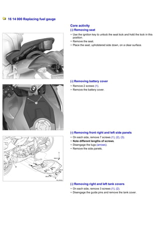
(-) Removing front right and left side panels
On each side, remove 7 screws (1), (2), (3).
Note different lengths of screws.
Disengage the lugs (arrows).
Remove the side panels.
(-) Removing right and left tank covers
On each side, remove 3 screws (1), (2).
Disengage the guide pins and remove the tank cover.
2. (-) Draining fuel tank
Warning
Fuel is flammable and a hazard to health.
Observe all applicable safety regulations.
Drain the fuel tank, using the commercially available special tool.
(-) Removing fuel tank
Disconnect overflow hose (1).
Remove screws (2) and carefully lift the fuel tank.
Disconnect quick-action coupling (3) and remove the fuel line.
Disconnect plugs of fuel pump (4) and fuel gauge (5).
Disconnect fuel tank breather hose (6) from the fuel-pump flange.
Lift the fuel tank up to remove.
(-) Removing fuel-tank cap and centre tank cover
Remove screws (1).
Remove the fuel-tank cap and the centre tank cover.
(-) Disengaging fuel-level sensor from fuel filler pipe
Carefully guide the fuel filler pipe out of the fuel tank.
Disengage the fuel-level sensor from retainer (1).
3. (-) Removing fuel pump unit
Remove the union nut with the pin wrench for fuel-tank ring (No. 16 1
021).
Attention
Failure to follow the correct procedure for removing the fuel pump can
damage the gasket at the fuel-pump flange, resulting in leaks
When removing the fuel pump, do not lever against the flange of the
pump unit.
Use the lug (arrow) to remove the fuel-pump unit from the fuel tank.
Carefully remove the fuel-pump unit with sealing ring, taking particular
care with the intake strainer.
Disconnect plug (1).
Open hose clamp (2) with pliers (No. 17 5 500) and disconnect the
breather hose.
(-) Replacing fuel-level sensor
Remove the corrugated hose shroud from the cable.
Remove the old fuel-level sensor from the fuel tank.
The new fuel-level sensor has to be calibrated when dry.
Connect the new fuel-level sensor to the fuel-pump unit while it is
removed from the fuel tank.
Connect the fuel-pump unit while still removed to the motorcycle.
Preparation for initialising/calibrating new parts
Precondition
Engine switched off.
Prop the motorcycle in such a way that it cannot move while
initialisation/calibration is in progress.
Motorcycle's battery is fully charged.
4. Note
Do not attempt to perform work of any other kind on the motorcycle while
programming/coding are in progress.
Switch off all electrical consumers.
Attention
Programming/coding is aborted if the voltage in the on-board system
drops below 12.6 volts.
Connect the charger to the battery.
Connect charger (No. 61 1 581) with cables (No. 61 1 582) to the
battery. While initialisation/calibration is in progress, do not connect or
disconnect the charger.
Connecting BMW Motorrad diagnostic system to motorcycle
Note
See the Instructions for Use supplied with the BMW Motorrad Group
Tester One for detailed information on initial startup, installation of the
operating system, diagnosis software and hardware periphery of the
GT1.
Connect BMW Motorrad battery charger (No. 61 1 581), (No. 61 1
582) to the motorcycle.
Begin by switching on the BMW Motorrad diagnostic system and wait
for it to power up.
The "Start Diagnosis" screen appears
From this point on, follow the instructions issued by the BMW
Motorrad diagnostic system.
Perform diagnosis. Rectify faults, if found, before starting
initialisation/calibration.
Start initialisation/calibration with the CIP program and follow the
instructions issued by the BMW Motorrad diagnostic system.
Disconnecting BMW Motorrad diagnostic system from the
motorcycle
Close all diagnostic programs and switch off the ignition.
Disconnect the BMW Motorrad diagnostic system from the motorcycle
and screw the cap onto the diagnosis plug.
Disconnect the BMW Motorrad battery charger from the motorcycle.
5. Lower the new fuel-level sensor into the left half of the fuel tank,
making sure that the clip is in the recess (detail).
Slip the cable into the corrugated hose shroud and route it to the
aperture for the pump.
(-) Securing fuel-level sensor to fuel filler pipe
Connect the breather hose and secure hose clamp (1) with pliers (No.
17 5 500).
Engage fuel-level sensor (2) in the retainer.
Carefully insert the fuel filler pipe into the fuel tank, making sure that
breather hole (1) is correctly positioned.
Introduce the bottom end of the fluid-level sensor into the left tank
pocket and route the plug and the breather hose to the opening for the
pump unit.
(-) Installing fuel-tank cap and centre tank cover
Position the centre tank cover on the fuel tank.
Make sure that the sealing ring is seated correctly under the fuel filler
pipe.
Hold the fuel filler cap in position and install screws (1).
Tightening torques
Fuel filler cap to fuel tank
M5 X 30 5 Nm
6. (-) Installing fuel pump unit
Check the sealing ring for damage; replace if necessary.
Grease the gasket at the seating face for the union nut.
Consumables/lubricants
Tyre mounting paste Assembly paste 36 32 1 239
263, 36 32 1
239 264
Position the sealing ring on the fuel tank.
Connect the breather hose and secure hose clamp (2) with pliers (No.
17 5 500).
Connect plug (1).
Carefully insert the fuel-pump unit into the fuel tank.
Install the union nut with the pin wrench for fuel-tank ring (No. 16 1
021).
Tightening torques
Pump unit to fuel tank
Sheet-metal screw cap 35 Nm
(-) Installing the fuel tank
Connect fuel tank breather hose (6) to the fuel-pump flange.
Connect plugs for fuel pump (4) and fuel gauge (5).
Check O-ring of quick-release coupling (3) for damage.
Attention
Lightly touching the latching pin of the female connector can cause the
connector to latch. If this happens and force is applied in an attempt to
close the male and female elements of the quick-action coupling,
damage to the O-rings can result, and the O-rings will leak.
Make sure that the latch is open/pressed when you connect the two
elements of the quick-action couplings in the fuel lines.
Open the latch on female coupling (3) of the fuel line and, applying
light pressure, press the male adapter into the female coupling until it
7. engages with an audible click.
Connect overflow hose (1) to the safety valve.
Position the fuel tank in the motorcycle.
Install screws (2) with spacing bushings and rubber washers.
Tightening torques
Fuel tank to retaining bridge, rear
M8 X 60 13 Nm
(-) Disconnecting BMW Motorrad diagnostic system from the
motorcycle
Close all diagnostic programs and switch off the ignition.
Disconnect the BMW Motorrad diagnostic system from the motorcycle
and screw the cap onto the diagnosis plug.
Disconnect the BMW Motorrad battery charger from the motorcycle.
(-) Filling fuel tank
Warning
Fuel is flammable and a hazard to health.
Observe all applicable safety regulations.
Fill the fuel tank with fuel.
Consumables/lubricants
Super Plus (premium), unleaded High-compression
98 octane (RON) fuel engines
(-) Installing front right and left side panels
Hold the side panels in position.
Engage the lugs (arrows).
On each side, install 7 screws (1), (2), (3).
Note different lengths of screws.
(-) Installing right and left tank covers
8. Make sure that heat insulator (1) is correctly positioned on the right-
hand side.
Engage the guide pins (arrows) and install the side panel.
On each side, install 3 screws (1), (2).
Note different lengths of screws.
(-) Installing battery cover
Install the battery cover.
Install 2 screws (1).
(-) Installing seat
Always make sure that cable (1) is correctly routed and clipped into
holder (2).
Engage the seat in the holder at the front.