SlideShare une entreprise Scribd logo
1  sur  40
1
CHAPTER I
AUTOMATION USING PLC’s-INTRODUCTION
Any industrial process or system basically involves various operations executed in a
particular sequence. If the operations are monitored and controlled by one or more people, it
is known as Manual control.
In case of automation the operations are carried out automatically, using sensors for
monitoring and electronic controllers for controlling. So the system runs automatically once it
is switched on.
As an example for automation a simple water filling system is explained this finds
wide application and can be implemented in every house.
In house we get municipal water (Manjeera) which will be first filled in the underground tank
generally called the Sump. From sump the water has to be pumped to the overhead tank
(OHT) from which the water is distributed to various outlets (taps). Whenever the ‘OHT’ is
empty we have to switch on the motor to pump the water from sump and we also have to
switch off the motor when tank is filled.
Before we switch on the motor we should see whether there is sufficient water in the
sump or else the motor will burn. There are two sensors S1 & S2 are fixed at the OHT to
sense the high and low level respectively. One sensor S3 to sense the minimum water level to
be maintained in the sump to pump water.
The automatic system monitors the sensors and switches the motor on whenever OHT
is empty (minimum level) sensed through sensor S2. The motor switches on only when
sufficient water is there in the sump sensed through sensor S3. The motor switches off
automatically when the tank is filled sensed through sensor S1.
S1
S2
Over-head tank
Motor
Fig 1.1: Automatic water filling system
S3
Sump
2
CHAPTER II
PROGRAMMABLE LOGIC CONTROLLERS (PLC’s)
A programmable controller is an industrial computer in which control devices such as
limit switches, push buttons, providing incoming control signals into the unit. The user
program also directs the PLC on how to control field devices like motors, starters, pilot lights
and solenoids.
A formal definition of a PLC comes from the National Electrical Manufactures
Association (NEMA)
“A Programmable logic controller is a digitally operated electronic system, designed
for use in an industrial environment, which uses a programmable memory for the internal
storage of user –oriented instructions for implementing specific functions such as logic,
sequencing, timing, counting and arithmetic to control, to digital or analog inputs and
outputs, various types of machines of process. Both the PLC and its associative peripherals
are designed so that they can be easily integrated into an industrial control system and easily
used in all their indented functions.
2.1 Use of PLC
The PLC is the tool that provides the control for an automated process. Automation will
help a manufacturing facility to:
1. Gain complete control of the manufacturing process.
2. Achieve constancy in manufacturing.
3. Improve quality and accuracy.
4. Working difficult or hazardous environment.
5. Increase productivity.
6. Shorten the time to market.
7. Lower the cost of quality, scrap, and rework.
8. Offer greater product variety.
9. Quickly change over from product to another.
10. Control inventory.
3
2.2Hard-wired Control Systems
In an industrial environment, electrical controls of many systems are generally wired
with relays and are usually called relay control.
The wiring between the control elements, such as sensors, solenoids etc., through
relays define the control “program”. Any modification to the “program” involves rewiring the
circuit. Therefore a hard-wired control system is constructed only after its program has been
defined.
Hard-wired controls are difficult to modify, when production requirements change
regularly. As an example, consider the relay control circuit shown in figure below:
Fig2.1: Relay control Fig2.2: PLC control
The Input Section consists of switches and sensors. The input devices transfer the
signals to the processing section. The Processing Section, which consists of relay coils and
contacts, determines the relationship between the inputs received and the output required. The
processed signals are transferred to the output section, where the output devices such as
solenoids, lamps or motors are driven.
+
K1
K2
+
LAMP
PB2PB1
K1 K2
INPUT
SECTION
24v
OUTPUT
SECTION
PROCESSING
SECTION
+
K1
K1
K2
PB2PB1
K2
I2
O1
+
LAMP
I1
PROGRAM
IF I1
AND I2
THEN SET O1
OTHERWISE RESET O1
PLC
24v
5v
4
2.3 Programmable Control Systems
An alternative to the hard-wired control system is the programmable control system.
In the system, a freely programmable electronic controller called Programmable Logic
Controller (PLC) replaces the function of relay portion of the hard-wired control. Figure- 2
depicts the concept of PLC Control as a replacement of relay coil and relay contacts of the
hard-wired control.
The PLC has an input section with a number of inputs designed to accept analog or
digital signals from switches and sensors.
The processor receives the input signals and processes the instructions in the program
with the status of the inputs and sends signals to drive the outputs. The program is written by
the user with aid of a PC or Programming Device and is downloaded in the Controller’s
program memory. The programs are written in the programming language like Ladder
Diagram or Statement List or Function Block Diagram with aid of the Programming software
specific to the PLC. The processor executes the program.
The PLC has an output section with a number of analog or digital outputs to drive the
output devices with its analog or digital signals.
PLCs are available in the market with fixed I/O design or modular design. Some of
the leading manufacturers of PLC are: Allen Bradley, Siemens, Mitsubishi, General Electric,
Omron, ABB, Fanuc etc.
2.4 Comparison of PLCs and Relays
Table 2.1: Comparison of PLC’s and Relays
CHARACTERISTIC PLC RELAY
Construction Easy to program Time consuming
Capable of complicated
Operations
Yes No
Ease of changing the
Control sequence
Very simple Very difficult
5
Physical size Very compact Bulky
Maintenance Excellent, PLCs rarely fail Poor, if large number of
contacts and coils have to
be maintained
2.5 Structure of PLC
A PLC is essentially a microcomputer with hardware, firmware and software. The
hardware consists of the actual device technology i.e. the PCBs, ICs, wires, battery, housing
etc. The firmware is the software part, which is permanently installed and supplied by the
PLC manufacturer. This includes the Operating System, which is generally stored in Read-
only-memory (ROM) or in the EPROM. The software is the user program written by the PLC
user. User programs are usually installed in the RAM (Random Access Memory), where they
can be easily modified.
Fig6 shows the fundamental design of a microcomputer. The PLC hardware is based
on a bus system. A bus system is a number of electrical lines divided into Address, data and
Control lines. The Address lines are used to select the address of a connected bus station. The
data lines are to transmit the required information. The control lines are necessary to activate
the correct bus station
Controlbus
Data bus
Address bus
Microprocessor
CPU
ROM
Operating
System
RAM
Program &
Data
Input
Module
Output
Module
Fig 2.3: Fundamental design of a microcomputer
6
2.6 System Components
The programmable logic controller consists essentially of the input modules, central
processing unit, program memory, output modules and power supply modules.
The inputs supplied by the switches/sensors are passed on to the central processing
unit through input modules. The signals generated by the central processing unit are prepared
by the output modules and passed onto the actuators.
The program is written by using an external programming device (PG) or a PC and
transferred (downloaded) into the program memory. A programming Device (PG) is a hand
held micro-computer with special compact design, suitable for industrial use.
2.6.1 Power Supply
The power supply is necessary to convert 120/230 V AC voltages to 24 V DC
required for the logic circuits of the processor and for the internal power required for the I/O
Acknowledge
ments (Limit
Switches &
Sensors)
Control
elements
(Pushbuttons
Switches)
Input
Modules Central
Processing
Unit
Output
Modules
Final
Control
Elements
Relays,
Solenoid
valves,
Lamps
etc.
Program
Memory
PLC
Power
Supply
Fig 2.4: Block diagram of a PLC
Programming
Device
7
modules. The power supply can be a separate unit or an integral part of the processor
depending on the manufacturer.
2.6.2 Input/output Section
The Input/output section consists of input and output modules. The input section
converts input voltages of 0 – 24 V DC or 120 – 240 V AC from discrete input devices to
low-level DC voltages (typically 5V) that the processor uses internally to represent status or
condition.
The input section can also convert 4 – 20 mA input signals to low-level DC signals
for the processor. Similarly the output section changes low-level DC signals from the
processor to 120 – 240 V AC or 24 V DC voltages required to operate the discrete output
devices.
The I/O section can be divided into two categories, namely fixed I/O and modular I/O.
The fixed I/O type has built-in inputs and outputs along with power supply and CPU. In the
modular I/O type, plug–in type units called I/O modules or signal modules (SMs) are added
as per the control requirement. Analog modules are used to process analog signals and digital
modules are used to process digital signals. The maximum number of I/Os that can be used is
PLC or CPU specific.
Analog input modules convert electrical signals corresponding to process values (e. g.
temperature) into digital values that can be processed by the CPU and analog output modules
convert digital values from the CPU into analog manipulated variables.
2.6.3 Input Modules
The function of an input module is to convert incoming signals into signals which can be
processed by the PLC and pass these to the central processing unit.
8
The input module contains an error voltage recognition facility, which is activated,
when the input voltage exceeds specified tolerance limits. A trigger circuit with signal delay
ensures that momentary interference peaks are suppressed. Opto-couplers separate internal
and external circuits so that interference is not able to penetrate the PLC through conductive
lines. The input modules also contain LEDs which indicate the status of the input signal.
2.6.4 Output Modules
The function of an output module is to convert the PLC signals into signal suitable for
the actuators
Fig 2.6: Block diagram of output module
Output
signal
Opto-coupler
Amplifier
Short-circuit
monitoring
Signal
from the
CPU
Signal to
processing
unit
Error voltage
detection Signal delay
Opto-coupler
Input
signal
Fig 2.5: Block diagram of input module
9
The opto-couplers are used to isolate the CPU signals from the external circuits in
order that no interference is received through conductive connections. The output signals
need to be amplified so that the final control elements and actuators which require additional
current can be directly connected to the output. The short-circuit-monitoring facility is to
protect the CPU from any short-circuit in the output.
2.6.5 Central Processing Unit
The CPU is the decision-maker or the brain of the system. It is a micro-processor
based system designed to execute the user programs. It can perform various arithmetic
functions, data manipulation and communication between local input/output section,
remotely located I/O sections and/or other networked PLCs.
2.7 Software
The processor of the programmable controller executes the application program
written by the user with the aid of a PC or a PG and stored in controller’s program memory.
The user programs are written with the programming software suitable for the specific PLC.
For example, STEP 5 or STEP 7 is the programming software for the Siemens PLCS and RS
Logic 500 is the programming software for the Allen Bradley PLCs.
ALU
Accumulator
Command register
Program Counter
Arithmetic unit Control unit
Control
bus Controlbus
Address bus
Data bus
Fig 2.7: Block diagram of CPU
10
Table 2.2: STEP 7 three methods of representation can be used to translate a program
into user program.
Ladder Diagram (LAD) Graphical representation of control task using relay
symbology.
Function Block Diagram (FBD) Graphical representation of control task using logic
boxes familiar from Boolean algebra.
Statement List (STL) Textual representation of control task using
mnemonic abbreviations.
2.8 Programming in general
The PLC programming language called “Ladder Diagram” uses symbolic
representation of switches and output devices to describe the operation of the system. The
Ladder Diagram (LAD) has two vertical sides. The left side is assumed to be connected to the
positive voltage source and right side to the zero volt. Between these vertical sides are the
horizontal current paths or rungs. Symbols representing various program elements such as
contacts and coils etc. are placed on the rungs in accordance with the operating sequence.
2.8.1 NO contact and NC contact (LAD)
LAD has two kinds of contacts for scanning bit operands:
 NO contact &
 NC contact
11
Table 2.3: Symbols of NO and NC
Normally open contact
(NO)
Scans for signal state “1”
Normally closed contact
(NC)
Scans for signal state “0”
2.8.1.1NO contact (LAD):
 Power flows through the NO contact, if the scanned “binary operand” has the
signal state “1”.
Fig 2.8: NO contact
PB1
K1
“0”
“0”
How an NO Contactworks?
K1
“1”
“1”
PB1
Activated
12
2.8.1.2 NC contact
For example, figures (a) and (b) shows the connections to control a lamp (L)
connected to the output with address Q 0.0 using two pushbuttons PB1 and PB2 connected to
the inputs with addresses I 0.0 and I 0.1 either in AND logic or in the OR logic. The
programs written in Ladder logic are also shown.
+
PB2PB1
24v
+
LAMP
PLC
+
PB2PB1
24v
+ LAMP
PLC
Fig 2.9: AND logic Fig 2.10: OR logic
13
Chapter III
SIEMENS PLCs
The concept of fully integrated automation describes a revolutionary new way of
combining the worlds of manufacturing and process engineering. All hardware and software
components are integrated into one single system: ‘SIMATIC’
The name SIMATIC was used as the synonym for SIEMENS programmable
controllers of S5 family. Now, the name ‘SIMATIC’ stands for fully integrated automation.
This complete integration is made possible by the universal compatibility offered by the
SIMATIC S7 system.
SIMATIC S7 consists of the following three types of programmable logic controllers
classified according to their performance range.
SIMATIC S7 200 SIMATIC S7 200 is a compact micro PLC designed for
application having the lowest performance range.
SIMATIC S7 300 SIMATIC S7 300 is a modular mini controller designed for
applications having intermediate performance range.
SIMATIC S7 400 SIMATIC S7 400 is designed for applications having a high
performance range.
Fig 3.1: Simatic Programmable controllers
14
3.1 SIMATIC S7 300 Programmable Controllers
An S7 – 300 Programmable Controller is made up of the following hardware components:
Table 3.1: Hardware components of S7-300
Racks
Accommodate the modules and connect them to each other.
Power Supply
module (PS)
Provides the internal supply voltages. Converts the power system
voltage (230V AC) to 24 V DC for S7 300 and for external loads.
Central
Processing Unit
(CPU)
Stores and processes the user program. Supplies the S7 300
backplane bus with 5V; communicates with other nodes in an MPI
network via the MPI interface.
Interface
Modules (IMs)
Connects the racks to one another.
Signal Modules
(SMs)
Adapt the signals from the system to the internal signal level or
control actuators via digital or analog signals.
Function
Modules (FMs)
Execute complex or time-critical and memory intensive processes
independently of the CPU, for example positioning or closed-loop
control.
Communication
Processors (CPs)
Establish the connection to subsidiary networks (subnets).
Subnets
Connect Programmable Controllers to each other or to other
devices.
PROFIBUS bus
cable with bus
connector
Interconnects stations on an MPI or PROFIBUS subnet.
15
3.2 System Memory
System memory contains the addresses that are accessed through the program.
Addresses may be, for example, inputs used to scan the signal states of PBs/ Limit switches,
or outputs.
The system memory on a CPU contains the following address areas:
Table 3.2: Symbols of address areas in CPU
Inputs I Images of digital input modules
Outputs Q Images of digital output modules
Bit memory M Stores of information accessible throughout
the whole program
Timers T Locations used to implement waiting and
monitoring times
Counters C Locations for up and down counting
Temporary local data L Locations used as dynamic intermediate
buffers (L stacks)
16
CHAPTER IV
BASIC PROCEDURE USING STEP 7
Step 7 projects can be created in two different orders:
Fig 4.1: Basic procedure for creating programs
4.1 Projects in STEP 7
In STEP 7, a project contains all the programs and data necessary for an automation
solution, regardless of the number of CPUs involved and how they are networked. Thus, a
project is not just limited to a user program used for a particular programmable module;
instead, it contains several user programs used for many programmable modules, which are
all stored together under a common project name.
With STEP 7, a system can be structured into projects. A project contains the entire
database for an automation solution. Creating a project or project structure is an essential
prerequisite for working with STEP 7
Designing the solution to the automation task
Creating a project
Configuring the hardware
Transferring the program to the CPU and debugging
Creating a program
Creating a program
Configuring the hardware
Option 2Option 1
17
Fig 4.2: Simatic manager
4.2 Project structure
A project structure can also be created easily using the project wizard as explained below:
 The default setting starts the STEP 7 Wizard, which assists you when creating a STEP
7 project. The project structure is used to store and arrange all the data and programs
in order.
 In the preview you can toggle the view of the project structure being created on and
off. To move to the next dialog box, click next.
 Select the appropriate CPU (say, CPU 313C-2DP, CPU 314 etc.).
 Every CPU has certain properties, say with regard to its memory configuration or
address areas etc. That is reason for selecting the CPU before starting the program.
 The MPI address (Multipoint Interface) is required in order for the CPU to
communicate with the programming device or PC. The default setting for the MPI
address is 2.
 Select the Organization Block OB1.
 OB1 represents the highest programming level and organizes other blocks in the S7
program.
 Select one of the programming languages: Ladder Logic (LAD), Statement List
(STL), or Function Block Diagram (FBD).
 The programming languages can be changed at a later stage.
 Double-click to select the suggested name in the “project name” field, say “Getting
started”.
18
 Click Make to generate the new project. The SIMATIC Manager will open with the
window for the Getting started” project
 If you create project without the STEP 7 Wizard, you must create each directory
within the project yourself.
Fig 4.3: Project structure
4.3 Working with Symbol Editor
Navigate in the project window until S7 Program (1) is reached. Double-click to open
the Symbols component and the symbol table is opened. The symbol table currently only
consists of the predefined Organization Block (OB1). Click the Cycle execution and
19
overwrite it with “Main Program”. Enter “PB_1” and the corresponding address, say I4.0 in
row 2.Complete the entries by pressing Enter. Similarly complete the entries in row 3 & 4
with PB_2 and LAMP along with their addresses respectively. In this way symbolic names
can be assigned to all the absolute addresses of the inputs and outputs in the program.
4.4 Programming a series circuit in Ladder Logic
In the following section, the steps to program a series circuit (AND) in Ladder Logic
(LAD) are explained.
In the same way, insert a second normally open (NO) contact and a coil from the tool
bar. The addresses of the NO contacts and the coil are still missing in the series circuit.
Enter the symbolic name “PB_2” for the second NO contact and “LAMP” for the coil.
Save the block, if there are no more symbols shown in red. Symbols are shown red, if they do
not exist in the symbol table, or if there is a syntax error.
 Select the current
path for the first
element.
 Click the NO contact
in the tool bar.
 Click the ??.? Sign and
enter the symbolic
name “PB_1”.
 Confirm with Enter.
20
You can also insert the symbolic name directly from the symbol table. Click the?Sign
and then the menu command Insert > Symbol. Scroll through the pull-down list until you
reach the corresponding name and select it. The symbolic name is added automatically.
21
CHAPTER V
INTRODUCTION TO PNEUMATICS
5.1 Pneumatics – Definition
The study of pneumatics deals with systems operated with air or other gaseous media.
The term “pneumatics” is derived from the Greek “pneuma”, meaning wind or breath. Hence
pneumatics may be defined as the study of movement of air. Pneumatics is concerned with
the use of compressed gaseous fluids to provide power or to control power.
5.2 Compressed air for transmitting power
Fig 5.1: A simplified pneumatic system
A simplified pneumatic system with only three blocks is given in figure 2.1. In
industry, the pneumatic medium generally used for transmitting power is the highly
compressible air. Since gaseous substances are compressible in ratios of reduction in volume
to increase in pressure, a compressor is used as a source of energy. The compressed air is
then prepared or treated in several stages to remove various contaminants present in it and
stored in a tank called receiver tank. Other factors of concern at this stage are the distribution
of air, regulation of pressure and lubrication of compressed air.
The compressed air medium is then used to do work in a controlled manner by being
allowed to expand back to the atmospheric pressure. The work done in this expansion is
transmitted to a load surface such as a piston or a vane, which will be moved by the
Power source
(Compressor)
Control
Valve
Actuator
(Cylinder)
Compressed airAir
22
expanding air with force equal to the pressure acting on the surface area (Force = Pressure x
Area).
The function of a pneumatic system can be summed up in the following simple terms:
Applying a force to a gaseous fluid like air and transmitting pneumatic pressure throughout
the fluid and converting the stored energy back into mechanical force before work can be
done.
5.3 Use of Pneumatics for automation
As explained above Pneumatics is basically energy system i.e. compressed air
converted to force and displacement to get work done. But the widely used energy is
electrical energy. So the question arises why electrical energy can’t be used for automation. It
can definitely be used, but the basic motion we get is rotational and when we require linear
motion, we have to convert rotary motion to linear by mechanical conversion. But in case of
Pneumatics the basic motion is linear and high speeds in the range of 4.5m/sec to 6m/sec can
be achieved. Hence Pneumatics is used widely for low cost automation.
Pneumatics finds application in industry sectors ranging from automotive
manufacturing to on-board commercial vehicles, from rail applications to printing and
textiles, from food packaging to process industries, from the electronic sector to medical care
and in thousands of other specialised industries.
5.4 Pneumatic system structure
A pneumatic system can be broken down into a number of levels representing
hardware and signal flow. The various levels form a control path for signal flow from the
signal (input) side to the work (output) side.
23
Fig 5.2: Pneumatic system structure
5.5 Energy supply ( )
Air in a pneumatic system must be clean and dry to reduce wear, at the required pressure
(regulated) and perhaps lubricated.
5.6 Pneumatic Actuators
The actuator group includes various types of linear and rotary actuators of varying size and
construction. Actuators can be broken down into the following groups:
Linear Actuators
 Single acting cylinder
 Double acting cylinder
Rotary Actuators
 Vane type
 Air motors
ACTUATING DEVICES
(OUTPUTS)
PROCESSING ELEMENTS
(PROCESSOR SIGNALS)
INPUT ELEMENTS
(INPUT SIGNALS)
ENERGY SUPPLY
(SOURCE)
FINAL CONTROL
ELEMENT
24
5.6.1 Single acting cylinder
With single acting cylinders, compressed air is applied on only one side of the piston
face. The other side is open to atmosphere. The cylinders can perform work in only one
direction. The return movement of the piston is effected by the application of an external
force or by a built-in spring as shown in figure below.
Fig 5.3: single acting cylinder
5.6.2 Double acting cylinder
With double acting cylinders, compressed air is applied on both sides of the piston
face. The cylinders can perform work in both directions as shown in figure below.
Fig 5.4: Double acting cylinder
5.6.3 Rotary actuator
The rotary actuator is compact with high torque ratings. The force is transmitted to the
drive shaft by a rotary vane. The range of angular movement is adjustable with end stops. The
angle can be adjusted between 0 º and 180 º.
Symbols
25
Table 5.1: symbols of types of cylinders
Single acting cylinder
Double acting cylinder
Rotary actuator
5.7 Pneumatic valves
A valve is used as a power valve for supply of working air to the actuator. A valve is also
used to alter, generate or cancel signals for the purpose of sensing, processing and
controlling. Valves can be divided into a number of groups according to their function:
 Directional control valve
 Non-return valve
 Flow control valve
 Pressure control valve
The directional control valve controls the passage of air signals by generating, canceling
or redirecting signals.
5.7.1 Representation of valves
A valve is described by:
 Number of ports -2 way, 3 way, 4 way, 5 way etc.
 Number of positions -2 positions, 3 positions etc.
 Method of actuation -Manual, Mechanical, Pneumatic, Electrical.
 Method of return actuation -spring returns etc.
26
Table 5.2: Representation of valves
3/2 directional control valve
(Normally closed)
3/2 directional control valve
(Normally open)
4/2 directional control valve
5/2 directional control valve
5.7.1.1 Flow control valve
Flow control valves (Throttle valves) influence the
volumetric flow of the compressed air, in both directions.
Fig5.5: flow control valve
5.7.1.2 Throttle relief valve
This is also called one-way flow control valve. In this valve air flow is throttled in one
direction only and the air can flow only through regulated cross-section. In the opposite
direction, the air can flow freely through the open check valve are used for speed regulated of
pneumatic cylinders.
Fig 5.6: Throttle relief valve
No. of ports
No. of positions
27
CHAPTER VI
ELECTRO-PNEMATICS
Electro-pneumatics is the result of integration of pneumatic and electrical
technologies. In such a system the electrical signals in the control part have to be
converted into actions by the pneumatic power part. The control part may consist of
sensors and pushbuttons for providing input signals. This information is passed to the
processing device such as a relay for processing the received signals. The processor
then drives the output stage of the system through the solenoid valves. The solenoid
valve is electrically actuated with a pneumatic output which is connected to the
actuator.
Table 6.1: System components
ACTUATORS
CONTROL
ELEMENTS
PROCESSORS
SENSORS
ENERGY SUPPLY
6.1 Solenoid
If a conductor is formed into the shape of one turn of coil and a current is
passed through it, an electromotive force (EMF) is generated. By increasing the
number of turns, the magnetic field is strengthened and the EMF is increased. The
EMF is greatly increased, if the wire is formed around an iron core. There is an
interesting property for the solenoid which is used in solenoid valves to get the
actuating force. An iron core which is displaced from the centre of the coil has the
28
tendency to move towards the centre of the coil when a current is drawn through the
coil, thus providing a linear motion. This linear motion can be used to actuate the
solenoid
Fig 6.1: Solenoid
6.2 Switches and pushbuttons
A switch is a device for making a circuit or breaking a circuit. A switch is primarily
distinguished by the type of contact:
Table 6.2: Switches
Normally open contact
(NO)
On actuation, enables energy flow
Normally closed contact
(NC)
On actuation, disables energy flow
Change-over contact
(CO)
A combination of NO and NC contacts
Soft iron core
29
6.2.1 Reed switch
Reed switches are also known as magnetically actuated proximity switches. In
its basic form the reed switch has a contact pair fused into an inert gas filled tube and
encapsulated in epoxy resin.
Reed switches are commonly used to sense the positions of pneumatic
cylinder piston rods and angle of rotation of the shaft in rotary actuators.
Fig 6.2: Reed switch
30
CHAPTER VII
AUTOMATIC STAMPING UNIT
Prefabricated parts are stamped automatically on a special pneumatic unit as
shown below. The parts are pushed form feed magazine into operating position
against a stop by Feed Cylinder 1 where they are clamped. Stamping Cylinder 2 then
extends slowly and stamps the part. After stamping, cylinder 2 & cylinder 1 return
one after the other. The parts are ejected (pushed in to the out bin) by the Ejector
Cylinder 3 and then returns back.
Fig 7.1: Automatic stamping unit
Cylinder 3
Cylinder 2
Cylinder 1
31
7.1 Construction
The system consists of three cylinders, namely
i. Feed cylinder or clamping cylinder
ii. Stamping cylinder
iii. Eject cylinder.
These cylinders (special cylinders with a magnetic band on the piston) have
Reed switch sensors fixed on them. Reed switches are also known as magnetically
actuated proximity switches. Each cylinder is with 2 reed switch sensors, one at the
piston side S1, other at Rod side S2, likewise S3, S4 for stamping cylinder and S5, S6
for the Eject cylinder respectively. Each cylinder is driven by the double solenoid
valve. As shown in the figure each valve has two coils. When we apply 24V to the
coil Y1, Y3, Y5 the valve changes its position and allows the air compressed air from
P to A port through which the air enters piston side port of the cylinder. At the same
time the rod side port of the cylinder which is connected to port B of the valve, is
routed to exhaust port S through inner path of the valve and air is released to exhaust
from the cylinder. Hence the cylinder piston along with rod moves forward and
known as forward stroke.
Similarly when the voltage signal is applied to Y2, Y4, and Y6 the valve
changes its position and allows the air from P to B port and releases air from port A
through exhaust port R. Hence piston moves back along with Rod is known as Return
stroke.
7.2 Control circuit
The control is implemented through a 6 step sequence as explained below.
Step1: Feed cylinder forward stroke A+, the cylinder brings the component to be
stamped from the feed magazine and clamps (holding the component tightly against
wall on the opposite side as shown in figure).
Step2: Stamping cylinder forward stroke B+, the stamping cylinder rod mounted
vertically comes down and stamps the component.
32
Step3: Stamping cylinder backward stroke B-, the stamping cylinder rod goes back to
home position.
Step4: Feed cylinder backward strike A-. The feed cylinder rod goes back to home
position leaving the stamped component.
Step5: Eject cylinder forward C+. The eject cylinder moves forward and pushes the
stamped component in the out bin.
Step6: Eject cylinder backward strike C-. The cylinder goes back to the home
position.
Fig 7.2: Displacement-step diagram Table 7.1: Assignment list
Clamping
Cylinder
A
1
0
Feed
Cylinder
B
1
0
Ejector
Cylinder
C
1
0
PB1 I0.0
PB2 I0.1
S1 I1.0
S2 I1.1
S3 I1.2
S4 I1.3
S5 I1.4
S6 I1.5
Y1 Q0.0
Y2 Q0.1
Y3 Q0.2
Y4 Q0.3
Y5 Q0.4
Y6 Q0.5
33
7.3 Ladder program explanation
The type of program used in PLC is ladder program. The control ladder
program contains 6 networks for 6 steps in serial order as mentioned above (6 steps).
Each network contains only memory element i.e. nothing but set/reset flip-flop.
Network 1:
Set control: A+
On the set side we have 2 NO contacts first contact activated by start button
and 2nd contact activated by sensor S5 which senses the backward stroke of eject
cylinder. This is the last step C- in the 6 step sequence. By checking this so we are
making sure that the previous cycle is completed. This has to be done essentially
before starting ,because sometimes the system may stop in the middle of the sequence
either due to mechanical problem (due to misalignment of sensors) or due to electrical
or pneumatic power failure. The system should not start unless previous cycle is
completed for safety reasons. So the system has to be brought back to initial state.
This is done by giving Mechanical Reset (MR) to bring back all the cylinders to home
position, followed by electronic Reset(ER) to bring back all the memory elements to
reset condition low state.
So when start button is pressed and S5 is activated by eject cylinder completing back
stroke C-, the signal passes to set side of memory M0.0 and sets it i.e. makes output
Q0.0 high and drives feed cylinder to forward strike.(A+)
Reset control:
This is activated by the NO contact driven by M0.1 i.e. when the next step is
activated. So step1 memory is reset when step2 memory is set. This is necessary as
once feed cylinder makes forward stroke, the output has to be switched back to low
state, for 2 reasons. Firstly to bring back the initial condition for next cycle and
secondly to allow backward stroke A- when the particular o/p is activated. The 2nd
‘NO’ in parallel is activated by ‘Electronic reset input’ (PB1) which is used to reset
all the outputs to initial condition to start a fresh cycle.
34
Network 2:
Set control: B+
This is driven by 2 NO contacts. 1st NO contact is activated by M0.0 i.e. when
previous step is executed. This makes sure that the sequence is maintained properly.
The 2ndNO is activated by S2 which is activated only when feed cylinder forward
stroke is executed successfully.
So only when previous step output is activated AND sensor S2 activated by execution
of forward stroke by feed cylinder, the signal passes to SET side of M0.1 and sets
output HIGH and drives Q0.2, and forward stroke of stamping cylinder B+ is
executed.
Reset control:
This is activated when the next step output M0.2 is activated in the sequence
or when the electronic reset push button (PB2-I0.1) is pressed.
Network 3:
Set control: B-
when the previous step outputM0.1 is activated and sensor S4 is activated by
forward stroke of the stamping cylinder, the signal passes to set side of M0.2 and
sets it high drives Q0.3 i.e. executing B- return stroke of stamping cylinder.
Reset control:
This is activated when the next step output M0.3 is activated in the sequence or when
the electronic reset push button (PB2-I0.1) is pressed.
Network 4:
Set control: A-
Activated when the previous output M0.2is actuated and sensor S3 is activated
by backward stroke of the stamping cylinder, the signal passes to set side of M0.3 and
sets it high, drives Q0.1 i.e. executing A- return stroke of clamping cylinder.
Reset control:
This is activated when the next step output M0.4 is activated in the sequence
or when the electronic reset push button (PB2-I0.1) is pressed.
35
Network 5:
Set control: C+
Activated when the previous output M0.3 is activated and sensor S1 is
activated by backward stroke of the clamping cylinder, the signal passes to set side of
M0.4 and sets it high, drives Q0.4 i.e. executing C+ Forward stroke of Eject
cylinder.
Reset control:
This is activated when the next step output M0.5 is activated in the sequence
or when the electronic reset push button (PB2-I0.1) is pressed.
Network 6:
Set control C-:
Activated when the previous output M0.4 is activated and sensor S6 is
activated by forward stroke of the eject cylinder, the signal passes to set side of M0.5
and sets it high drives Q0.5 i.e. executing C- return stroke of eject cylinder.
Reset control:
This is activated when the next step output M0.0 is activated in the sequence
or when the Mechanical Reset push button (PB3-I0.2) is pressed.
MR: PB3 (I 0.2)
Mechanical Reset is given to SET side of all Memory elements that control
Return stroke of all cylinders. So all the cylinders execute return stroke and the
mechanical system attains initial state.
ER: PB2 (I 0.1)
Electronic Reset is used to bring back all the memory elements to reset
condition low state and the electronic control system attains initial state.
36
7.4 Pneumatic circuit
Fig 7.3: Pneumatic circuit
For speed
control
Double
solenoid
37
Fig 7.4: PLC software circuit 1
Start I0.0 S5
M0.1
Q0.0
M0.0
ER
M0.1 S2
M0.2
ER
M0.1
M0.1 S4
Q0.2
M0.2
M0.3
Q0.3
M0.4
M0.2
ER
M0.3
Q0.1
ER
S3
38
Fig 7.5: PLC software circuit 2
M0.3
M0.5
S1 Q0.4
M0.4
ER
S6
M0.5
M0.4
M0.0
Q0.5
ER
39
CONCLUSIONS
P L C systems have within the industrial process and as such have established
a strong presence in modern industry. Continuous development of pneumatic power
technology has significantly expanded and increased the applications of PLC to many
areas hitherto unknown for adopting pneumatics. Among many applications and users
of PLC along with pneumatic systems are:
Aircraft manufacturers
Cement plants
Chemical plants
Coal mines
Cotton mills
Dairies
Distilleries
Forge shops
Foundries and steel mills
Oil refineries
40

Contenu connexe

Tendances

PLC and SCADA training.
PLC and SCADA training.PLC and SCADA training.
PLC and SCADA training.Ishank Ranjan
 
PLC based load managment
PLC based load managmentPLC based load managment
PLC based load managmentmanishkumarm
 
automation slides,plc,scada,HMI
automation slides,plc,scada,HMIautomation slides,plc,scada,HMI
automation slides,plc,scada,HMIBOSCH
 
De-Inking Plant Final Tower Control using SIEMENS PLC(report
De-Inking Plant Final Tower Control using SIEMENS PLC(reportDe-Inking Plant Final Tower Control using SIEMENS PLC(report
De-Inking Plant Final Tower Control using SIEMENS PLC(reportabdullah s
 
Parking Control System using PLC
Parking Control System using PLCParking Control System using PLC
Parking Control System using PLCZunAib Ali
 
Basic plc-programming-e book_Reliance High Tech Ltd
Basic plc-programming-e book_Reliance High Tech LtdBasic plc-programming-e book_Reliance High Tech Ltd
Basic plc-programming-e book_Reliance High Tech LtdMarsus Marsus
 
PLC Circuit Design And Basic Programming By Manish kumar
PLC Circuit Design And Basic Programming By Manish kumarPLC Circuit Design And Basic Programming By Manish kumar
PLC Circuit Design And Basic Programming By Manish kumarmanishkumarm
 

Tendances (20)

PLC and SCADA training.
PLC and SCADA training.PLC and SCADA training.
PLC and SCADA training.
 
Basic PLC
Basic PLCBasic PLC
Basic PLC
 
Basic plc
Basic plcBasic plc
Basic plc
 
PLC presentation
PLC presentationPLC presentation
PLC presentation
 
PLC, by Mohamed Al-Emam, Session 1
PLC, by Mohamed Al-Emam, Session 1PLC, by Mohamed Al-Emam, Session 1
PLC, by Mohamed Al-Emam, Session 1
 
PLC based load managment
PLC based load managmentPLC based load managment
PLC based load managment
 
Basic plc
Basic plcBasic plc
Basic plc
 
automation slides,plc,scada,HMI
automation slides,plc,scada,HMIautomation slides,plc,scada,HMI
automation slides,plc,scada,HMI
 
Programmable logic controllers
Programmable logic controllersProgrammable logic controllers
Programmable logic controllers
 
Basic PLC
Basic PLCBasic PLC
Basic PLC
 
Presentaton on Plc & Scada
Presentaton on Plc & ScadaPresentaton on Plc & Scada
Presentaton on Plc & Scada
 
Basic plc
Basic plcBasic plc
Basic plc
 
Basic plc
Basic plcBasic plc
Basic plc
 
Basic plc
Basic plcBasic plc
Basic plc
 
De-Inking Plant Final Tower Control using SIEMENS PLC(report
De-Inking Plant Final Tower Control using SIEMENS PLC(reportDe-Inking Plant Final Tower Control using SIEMENS PLC(report
De-Inking Plant Final Tower Control using SIEMENS PLC(report
 
Parking Control System using PLC
Parking Control System using PLCParking Control System using PLC
Parking Control System using PLC
 
Basic plc-programming-e book_Reliance High Tech Ltd
Basic plc-programming-e book_Reliance High Tech LtdBasic plc-programming-e book_Reliance High Tech Ltd
Basic plc-programming-e book_Reliance High Tech Ltd
 
Plc
PlcPlc
Plc
 
PLC Circuit Design And Basic Programming By Manish kumar
PLC Circuit Design And Basic Programming By Manish kumarPLC Circuit Design And Basic Programming By Manish kumar
PLC Circuit Design And Basic Programming By Manish kumar
 
Q gx developer_e
Q gx developer_eQ gx developer_e
Q gx developer_e
 

En vedette (11)

Presentación1
Presentación1Presentación1
Presentación1
 
ROAD-SHOW.pptx-01
ROAD-SHOW.pptx-01ROAD-SHOW.pptx-01
ROAD-SHOW.pptx-01
 
Presentación1
Presentación1Presentación1
Presentación1
 
Día 18 de mayo de la revolución de david y manuel
Día 18 de mayo de la revolución de david y manuelDía 18 de mayo de la revolución de david y manuel
Día 18 de mayo de la revolución de david y manuel
 
PTF original logo
PTF original logoPTF original logo
PTF original logo
 
DERECHO AGRARIO
DERECHO AGRARIODERECHO AGRARIO
DERECHO AGRARIO
 
Anannya Patra_CV
Anannya Patra_CVAnannya Patra_CV
Anannya Patra_CV
 
CV
CVCV
CV
 
Volume Morto Nunca Mais
Volume Morto Nunca MaisVolume Morto Nunca Mais
Volume Morto Nunca Mais
 
Acertando suas Contas
Acertando suas ContasAcertando suas Contas
Acertando suas Contas
 
Hana's grainger resume march 2016
Hana's grainger resume march 2016Hana's grainger resume march 2016
Hana's grainger resume march 2016
 

Similaire à documentation (1)

Industrial Automation EMERSON EDUARDO RODRIGUES
Industrial Automation EMERSON EDUARDO RODRIGUESIndustrial Automation EMERSON EDUARDO RODRIGUES
Industrial Automation EMERSON EDUARDO RODRIGUESEMERSON EDUARDO RODRIGUES
 
R22EM807_PAVAN.D_PLC.pptx
R22EM807_PAVAN.D_PLC.pptxR22EM807_PAVAN.D_PLC.pptx
R22EM807_PAVAN.D_PLC.pptxBCGowtham1
 
Programmable Logic Controller Training Day 1 to 3.pptx
Programmable Logic Controller  Training Day 1 to 3.pptxProgrammable Logic Controller  Training Day 1 to 3.pptx
Programmable Logic Controller Training Day 1 to 3.pptxdmckinseyrecruitment
 
Basic plc
Basic plcBasic plc
Basic plcmnamky
 
EE415 LT 1.pptxDFHDFHDFHHFDDFHFDHDFHDFHF
EE415 LT 1.pptxDFHDFHDFHHFDDFHFDHDFHDFHFEE415 LT 1.pptxDFHDFHDFHHFDDFHFDHDFHDFHF
EE415 LT 1.pptxDFHDFHDFHHFDDFHFDHDFHDFHF2013471
 
1 introduction to plc and its programming-1
1 introduction to plc and its programming-11 introduction to plc and its programming-1
1 introduction to plc and its programming-1VishalGupta969
 
Plc (PROGRAMMABLE LOGIC CONTROLLER)
Plc (PROGRAMMABLE LOGIC CONTROLLER)Plc (PROGRAMMABLE LOGIC CONTROLLER)
Plc (PROGRAMMABLE LOGIC CONTROLLER)Urval Chotalia
 
Implementation of T-Junction Traffic Light Control System Using Simatic S7-20...
Implementation of T-Junction Traffic Light Control System Using Simatic S7-20...Implementation of T-Junction Traffic Light Control System Using Simatic S7-20...
Implementation of T-Junction Traffic Light Control System Using Simatic S7-20...IJERA Editor
 
Introduction to PLC
Introduction to PLCIntroduction to PLC
Introduction to PLCVeerakumar S
 

Similaire à documentation (1) (20)

Industrial Automation EMERSON EDUARDO RODRIGUES
Industrial Automation EMERSON EDUARDO RODRIGUESIndustrial Automation EMERSON EDUARDO RODRIGUES
Industrial Automation EMERSON EDUARDO RODRIGUES
 
R22EM807_PAVAN.D_PLC.pptx
R22EM807_PAVAN.D_PLC.pptxR22EM807_PAVAN.D_PLC.pptx
R22EM807_PAVAN.D_PLC.pptx
 
plc introduction
plc introductionplc introduction
plc introduction
 
Basic PLC.ppt
Basic PLC.pptBasic PLC.ppt
Basic PLC.ppt
 
Programmable Logic Controller Training Day 1 to 3.pptx
Programmable Logic Controller  Training Day 1 to 3.pptxProgrammable Logic Controller  Training Day 1 to 3.pptx
Programmable Logic Controller Training Day 1 to 3.pptx
 
Plc notes
Plc notesPlc notes
Plc notes
 
Basics of plc
Basics of plcBasics of plc
Basics of plc
 
Basic plc
Basic plcBasic plc
Basic plc
 
Basic plc
Basic plcBasic plc
Basic plc
 
Plc
PlcPlc
Plc
 
EE415 LT 1.pptxDFHDFHDFHHFDDFHFDHDFHDFHF
EE415 LT 1.pptxDFHDFHDFHHFDDFHFDHDFHDFHFEE415 LT 1.pptxDFHDFHDFHHFDDFHFDHDFHDFHF
EE415 LT 1.pptxDFHDFHDFHHFDDFHFDHDFHDFHF
 
I012455457
I012455457I012455457
I012455457
 
Unit - 1.pptx
Unit - 1.pptxUnit - 1.pptx
Unit - 1.pptx
 
1 introduction to plc and its programming-1
1 introduction to plc and its programming-11 introduction to plc and its programming-1
1 introduction to plc and its programming-1
 
UNIT-IV.ppt
UNIT-IV.pptUNIT-IV.ppt
UNIT-IV.ppt
 
PLCandSCADA.pdf
PLCandSCADA.pdfPLCandSCADA.pdf
PLCandSCADA.pdf
 
Plc (PROGRAMMABLE LOGIC CONTROLLER)
Plc (PROGRAMMABLE LOGIC CONTROLLER)Plc (PROGRAMMABLE LOGIC CONTROLLER)
Plc (PROGRAMMABLE LOGIC CONTROLLER)
 
Implementation of T-Junction Traffic Light Control System Using Simatic S7-20...
Implementation of T-Junction Traffic Light Control System Using Simatic S7-20...Implementation of T-Junction Traffic Light Control System Using Simatic S7-20...
Implementation of T-Junction Traffic Light Control System Using Simatic S7-20...
 
Introduction to PLC
Introduction to PLCIntroduction to PLC
Introduction to PLC
 
PLC operation part 1
PLC operation part 1PLC operation part 1
PLC operation part 1
 

documentation (1)

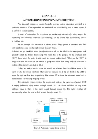
  • 1. 1 CHAPTER I AUTOMATION USING PLC’s-INTRODUCTION Any industrial process or system basically involves various operations executed in a particular sequence. If the operations are monitored and controlled by one or more people, it is known as Manual control. In case of automation the operations are carried out automatically, using sensors for monitoring and electronic controllers for controlling. So the system runs automatically once it is switched on. As an example for automation a simple water filling system is explained this finds wide application and can be implemented in every house. In house we get municipal water (Manjeera) which will be first filled in the underground tank generally called the Sump. From sump the water has to be pumped to the overhead tank (OHT) from which the water is distributed to various outlets (taps). Whenever the ‘OHT’ is empty we have to switch on the motor to pump the water from sump and we also have to switch off the motor when tank is filled. Before we switch on the motor we should see whether there is sufficient water in the sump or else the motor will burn. There are two sensors S1 & S2 are fixed at the OHT to sense the high and low level respectively. One sensor S3 to sense the minimum water level to be maintained in the sump to pump water. The automatic system monitors the sensors and switches the motor on whenever OHT is empty (minimum level) sensed through sensor S2. The motor switches on only when sufficient water is there in the sump sensed through sensor S3. The motor switches off automatically when the tank is filled sensed through sensor S1. S1 S2 Over-head tank Motor Fig 1.1: Automatic water filling system S3 Sump
  • 2. 2 CHAPTER II PROGRAMMABLE LOGIC CONTROLLERS (PLC’s) A programmable controller is an industrial computer in which control devices such as limit switches, push buttons, providing incoming control signals into the unit. The user program also directs the PLC on how to control field devices like motors, starters, pilot lights and solenoids. A formal definition of a PLC comes from the National Electrical Manufactures Association (NEMA) “A Programmable logic controller is a digitally operated electronic system, designed for use in an industrial environment, which uses a programmable memory for the internal storage of user –oriented instructions for implementing specific functions such as logic, sequencing, timing, counting and arithmetic to control, to digital or analog inputs and outputs, various types of machines of process. Both the PLC and its associative peripherals are designed so that they can be easily integrated into an industrial control system and easily used in all their indented functions. 2.1 Use of PLC The PLC is the tool that provides the control for an automated process. Automation will help a manufacturing facility to: 1. Gain complete control of the manufacturing process. 2. Achieve constancy in manufacturing. 3. Improve quality and accuracy. 4. Working difficult or hazardous environment. 5. Increase productivity. 6. Shorten the time to market. 7. Lower the cost of quality, scrap, and rework. 8. Offer greater product variety. 9. Quickly change over from product to another. 10. Control inventory.
  • 3. 3 2.2Hard-wired Control Systems In an industrial environment, electrical controls of many systems are generally wired with relays and are usually called relay control. The wiring between the control elements, such as sensors, solenoids etc., through relays define the control “program”. Any modification to the “program” involves rewiring the circuit. Therefore a hard-wired control system is constructed only after its program has been defined. Hard-wired controls are difficult to modify, when production requirements change regularly. As an example, consider the relay control circuit shown in figure below: Fig2.1: Relay control Fig2.2: PLC control The Input Section consists of switches and sensors. The input devices transfer the signals to the processing section. The Processing Section, which consists of relay coils and contacts, determines the relationship between the inputs received and the output required. The processed signals are transferred to the output section, where the output devices such as solenoids, lamps or motors are driven. + K1 K2 + LAMP PB2PB1 K1 K2 INPUT SECTION 24v OUTPUT SECTION PROCESSING SECTION + K1 K1 K2 PB2PB1 K2 I2 O1 + LAMP I1 PROGRAM IF I1 AND I2 THEN SET O1 OTHERWISE RESET O1 PLC 24v 5v
  • 4. 4 2.3 Programmable Control Systems An alternative to the hard-wired control system is the programmable control system. In the system, a freely programmable electronic controller called Programmable Logic Controller (PLC) replaces the function of relay portion of the hard-wired control. Figure- 2 depicts the concept of PLC Control as a replacement of relay coil and relay contacts of the hard-wired control. The PLC has an input section with a number of inputs designed to accept analog or digital signals from switches and sensors. The processor receives the input signals and processes the instructions in the program with the status of the inputs and sends signals to drive the outputs. The program is written by the user with aid of a PC or Programming Device and is downloaded in the Controller’s program memory. The programs are written in the programming language like Ladder Diagram or Statement List or Function Block Diagram with aid of the Programming software specific to the PLC. The processor executes the program. The PLC has an output section with a number of analog or digital outputs to drive the output devices with its analog or digital signals. PLCs are available in the market with fixed I/O design or modular design. Some of the leading manufacturers of PLC are: Allen Bradley, Siemens, Mitsubishi, General Electric, Omron, ABB, Fanuc etc. 2.4 Comparison of PLCs and Relays Table 2.1: Comparison of PLC’s and Relays CHARACTERISTIC PLC RELAY Construction Easy to program Time consuming Capable of complicated Operations Yes No Ease of changing the Control sequence Very simple Very difficult
  • 5. 5 Physical size Very compact Bulky Maintenance Excellent, PLCs rarely fail Poor, if large number of contacts and coils have to be maintained 2.5 Structure of PLC A PLC is essentially a microcomputer with hardware, firmware and software. The hardware consists of the actual device technology i.e. the PCBs, ICs, wires, battery, housing etc. The firmware is the software part, which is permanently installed and supplied by the PLC manufacturer. This includes the Operating System, which is generally stored in Read- only-memory (ROM) or in the EPROM. The software is the user program written by the PLC user. User programs are usually installed in the RAM (Random Access Memory), where they can be easily modified. Fig6 shows the fundamental design of a microcomputer. The PLC hardware is based on a bus system. A bus system is a number of electrical lines divided into Address, data and Control lines. The Address lines are used to select the address of a connected bus station. The data lines are to transmit the required information. The control lines are necessary to activate the correct bus station Controlbus Data bus Address bus Microprocessor CPU ROM Operating System RAM Program & Data Input Module Output Module Fig 2.3: Fundamental design of a microcomputer
  • 6. 6 2.6 System Components The programmable logic controller consists essentially of the input modules, central processing unit, program memory, output modules and power supply modules. The inputs supplied by the switches/sensors are passed on to the central processing unit through input modules. The signals generated by the central processing unit are prepared by the output modules and passed onto the actuators. The program is written by using an external programming device (PG) or a PC and transferred (downloaded) into the program memory. A programming Device (PG) is a hand held micro-computer with special compact design, suitable for industrial use. 2.6.1 Power Supply The power supply is necessary to convert 120/230 V AC voltages to 24 V DC required for the logic circuits of the processor and for the internal power required for the I/O Acknowledge ments (Limit Switches & Sensors) Control elements (Pushbuttons Switches) Input Modules Central Processing Unit Output Modules Final Control Elements Relays, Solenoid valves, Lamps etc. Program Memory PLC Power Supply Fig 2.4: Block diagram of a PLC Programming Device
  • 7. 7 modules. The power supply can be a separate unit or an integral part of the processor depending on the manufacturer. 2.6.2 Input/output Section The Input/output section consists of input and output modules. The input section converts input voltages of 0 – 24 V DC or 120 – 240 V AC from discrete input devices to low-level DC voltages (typically 5V) that the processor uses internally to represent status or condition. The input section can also convert 4 – 20 mA input signals to low-level DC signals for the processor. Similarly the output section changes low-level DC signals from the processor to 120 – 240 V AC or 24 V DC voltages required to operate the discrete output devices. The I/O section can be divided into two categories, namely fixed I/O and modular I/O. The fixed I/O type has built-in inputs and outputs along with power supply and CPU. In the modular I/O type, plug–in type units called I/O modules or signal modules (SMs) are added as per the control requirement. Analog modules are used to process analog signals and digital modules are used to process digital signals. The maximum number of I/Os that can be used is PLC or CPU specific. Analog input modules convert electrical signals corresponding to process values (e. g. temperature) into digital values that can be processed by the CPU and analog output modules convert digital values from the CPU into analog manipulated variables. 2.6.3 Input Modules The function of an input module is to convert incoming signals into signals which can be processed by the PLC and pass these to the central processing unit.
  • 8. 8 The input module contains an error voltage recognition facility, which is activated, when the input voltage exceeds specified tolerance limits. A trigger circuit with signal delay ensures that momentary interference peaks are suppressed. Opto-couplers separate internal and external circuits so that interference is not able to penetrate the PLC through conductive lines. The input modules also contain LEDs which indicate the status of the input signal. 2.6.4 Output Modules The function of an output module is to convert the PLC signals into signal suitable for the actuators Fig 2.6: Block diagram of output module Output signal Opto-coupler Amplifier Short-circuit monitoring Signal from the CPU Signal to processing unit Error voltage detection Signal delay Opto-coupler Input signal Fig 2.5: Block diagram of input module
  • 9. 9 The opto-couplers are used to isolate the CPU signals from the external circuits in order that no interference is received through conductive connections. The output signals need to be amplified so that the final control elements and actuators which require additional current can be directly connected to the output. The short-circuit-monitoring facility is to protect the CPU from any short-circuit in the output. 2.6.5 Central Processing Unit The CPU is the decision-maker or the brain of the system. It is a micro-processor based system designed to execute the user programs. It can perform various arithmetic functions, data manipulation and communication between local input/output section, remotely located I/O sections and/or other networked PLCs. 2.7 Software The processor of the programmable controller executes the application program written by the user with the aid of a PC or a PG and stored in controller’s program memory. The user programs are written with the programming software suitable for the specific PLC. For example, STEP 5 or STEP 7 is the programming software for the Siemens PLCS and RS Logic 500 is the programming software for the Allen Bradley PLCs. ALU Accumulator Command register Program Counter Arithmetic unit Control unit Control bus Controlbus Address bus Data bus Fig 2.7: Block diagram of CPU
  • 10. 10 Table 2.2: STEP 7 three methods of representation can be used to translate a program into user program. Ladder Diagram (LAD) Graphical representation of control task using relay symbology. Function Block Diagram (FBD) Graphical representation of control task using logic boxes familiar from Boolean algebra. Statement List (STL) Textual representation of control task using mnemonic abbreviations. 2.8 Programming in general The PLC programming language called “Ladder Diagram” uses symbolic representation of switches and output devices to describe the operation of the system. The Ladder Diagram (LAD) has two vertical sides. The left side is assumed to be connected to the positive voltage source and right side to the zero volt. Between these vertical sides are the horizontal current paths or rungs. Symbols representing various program elements such as contacts and coils etc. are placed on the rungs in accordance with the operating sequence. 2.8.1 NO contact and NC contact (LAD) LAD has two kinds of contacts for scanning bit operands:  NO contact &  NC contact
  • 11. 11 Table 2.3: Symbols of NO and NC Normally open contact (NO) Scans for signal state “1” Normally closed contact (NC) Scans for signal state “0” 2.8.1.1NO contact (LAD):  Power flows through the NO contact, if the scanned “binary operand” has the signal state “1”. Fig 2.8: NO contact PB1 K1 “0” “0” How an NO Contactworks? K1 “1” “1” PB1 Activated
  • 12. 12 2.8.1.2 NC contact For example, figures (a) and (b) shows the connections to control a lamp (L) connected to the output with address Q 0.0 using two pushbuttons PB1 and PB2 connected to the inputs with addresses I 0.0 and I 0.1 either in AND logic or in the OR logic. The programs written in Ladder logic are also shown. + PB2PB1 24v + LAMP PLC + PB2PB1 24v + LAMP PLC Fig 2.9: AND logic Fig 2.10: OR logic
  • 13. 13 Chapter III SIEMENS PLCs The concept of fully integrated automation describes a revolutionary new way of combining the worlds of manufacturing and process engineering. All hardware and software components are integrated into one single system: ‘SIMATIC’ The name SIMATIC was used as the synonym for SIEMENS programmable controllers of S5 family. Now, the name ‘SIMATIC’ stands for fully integrated automation. This complete integration is made possible by the universal compatibility offered by the SIMATIC S7 system. SIMATIC S7 consists of the following three types of programmable logic controllers classified according to their performance range. SIMATIC S7 200 SIMATIC S7 200 is a compact micro PLC designed for application having the lowest performance range. SIMATIC S7 300 SIMATIC S7 300 is a modular mini controller designed for applications having intermediate performance range. SIMATIC S7 400 SIMATIC S7 400 is designed for applications having a high performance range. Fig 3.1: Simatic Programmable controllers
  • 14. 14 3.1 SIMATIC S7 300 Programmable Controllers An S7 – 300 Programmable Controller is made up of the following hardware components: Table 3.1: Hardware components of S7-300 Racks Accommodate the modules and connect them to each other. Power Supply module (PS) Provides the internal supply voltages. Converts the power system voltage (230V AC) to 24 V DC for S7 300 and for external loads. Central Processing Unit (CPU) Stores and processes the user program. Supplies the S7 300 backplane bus with 5V; communicates with other nodes in an MPI network via the MPI interface. Interface Modules (IMs) Connects the racks to one another. Signal Modules (SMs) Adapt the signals from the system to the internal signal level or control actuators via digital or analog signals. Function Modules (FMs) Execute complex or time-critical and memory intensive processes independently of the CPU, for example positioning or closed-loop control. Communication Processors (CPs) Establish the connection to subsidiary networks (subnets). Subnets Connect Programmable Controllers to each other or to other devices. PROFIBUS bus cable with bus connector Interconnects stations on an MPI or PROFIBUS subnet.
  • 15. 15 3.2 System Memory System memory contains the addresses that are accessed through the program. Addresses may be, for example, inputs used to scan the signal states of PBs/ Limit switches, or outputs. The system memory on a CPU contains the following address areas: Table 3.2: Symbols of address areas in CPU Inputs I Images of digital input modules Outputs Q Images of digital output modules Bit memory M Stores of information accessible throughout the whole program Timers T Locations used to implement waiting and monitoring times Counters C Locations for up and down counting Temporary local data L Locations used as dynamic intermediate buffers (L stacks)
  • 16. 16 CHAPTER IV BASIC PROCEDURE USING STEP 7 Step 7 projects can be created in two different orders: Fig 4.1: Basic procedure for creating programs 4.1 Projects in STEP 7 In STEP 7, a project contains all the programs and data necessary for an automation solution, regardless of the number of CPUs involved and how they are networked. Thus, a project is not just limited to a user program used for a particular programmable module; instead, it contains several user programs used for many programmable modules, which are all stored together under a common project name. With STEP 7, a system can be structured into projects. A project contains the entire database for an automation solution. Creating a project or project structure is an essential prerequisite for working with STEP 7 Designing the solution to the automation task Creating a project Configuring the hardware Transferring the program to the CPU and debugging Creating a program Creating a program Configuring the hardware Option 2Option 1
  • 17. 17 Fig 4.2: Simatic manager 4.2 Project structure A project structure can also be created easily using the project wizard as explained below:  The default setting starts the STEP 7 Wizard, which assists you when creating a STEP 7 project. The project structure is used to store and arrange all the data and programs in order.  In the preview you can toggle the view of the project structure being created on and off. To move to the next dialog box, click next.  Select the appropriate CPU (say, CPU 313C-2DP, CPU 314 etc.).  Every CPU has certain properties, say with regard to its memory configuration or address areas etc. That is reason for selecting the CPU before starting the program.  The MPI address (Multipoint Interface) is required in order for the CPU to communicate with the programming device or PC. The default setting for the MPI address is 2.  Select the Organization Block OB1.  OB1 represents the highest programming level and organizes other blocks in the S7 program.  Select one of the programming languages: Ladder Logic (LAD), Statement List (STL), or Function Block Diagram (FBD).  The programming languages can be changed at a later stage.  Double-click to select the suggested name in the “project name” field, say “Getting started”.
  • 18. 18  Click Make to generate the new project. The SIMATIC Manager will open with the window for the Getting started” project  If you create project without the STEP 7 Wizard, you must create each directory within the project yourself. Fig 4.3: Project structure 4.3 Working with Symbol Editor Navigate in the project window until S7 Program (1) is reached. Double-click to open the Symbols component and the symbol table is opened. The symbol table currently only consists of the predefined Organization Block (OB1). Click the Cycle execution and
  • 19. 19 overwrite it with “Main Program”. Enter “PB_1” and the corresponding address, say I4.0 in row 2.Complete the entries by pressing Enter. Similarly complete the entries in row 3 & 4 with PB_2 and LAMP along with their addresses respectively. In this way symbolic names can be assigned to all the absolute addresses of the inputs and outputs in the program. 4.4 Programming a series circuit in Ladder Logic In the following section, the steps to program a series circuit (AND) in Ladder Logic (LAD) are explained. In the same way, insert a second normally open (NO) contact and a coil from the tool bar. The addresses of the NO contacts and the coil are still missing in the series circuit. Enter the symbolic name “PB_2” for the second NO contact and “LAMP” for the coil. Save the block, if there are no more symbols shown in red. Symbols are shown red, if they do not exist in the symbol table, or if there is a syntax error.  Select the current path for the first element.  Click the NO contact in the tool bar.  Click the ??.? Sign and enter the symbolic name “PB_1”.  Confirm with Enter.
  • 20. 20 You can also insert the symbolic name directly from the symbol table. Click the?Sign and then the menu command Insert > Symbol. Scroll through the pull-down list until you reach the corresponding name and select it. The symbolic name is added automatically.
  • 21. 21 CHAPTER V INTRODUCTION TO PNEUMATICS 5.1 Pneumatics – Definition The study of pneumatics deals with systems operated with air or other gaseous media. The term “pneumatics” is derived from the Greek “pneuma”, meaning wind or breath. Hence pneumatics may be defined as the study of movement of air. Pneumatics is concerned with the use of compressed gaseous fluids to provide power or to control power. 5.2 Compressed air for transmitting power Fig 5.1: A simplified pneumatic system A simplified pneumatic system with only three blocks is given in figure 2.1. In industry, the pneumatic medium generally used for transmitting power is the highly compressible air. Since gaseous substances are compressible in ratios of reduction in volume to increase in pressure, a compressor is used as a source of energy. The compressed air is then prepared or treated in several stages to remove various contaminants present in it and stored in a tank called receiver tank. Other factors of concern at this stage are the distribution of air, regulation of pressure and lubrication of compressed air. The compressed air medium is then used to do work in a controlled manner by being allowed to expand back to the atmospheric pressure. The work done in this expansion is transmitted to a load surface such as a piston or a vane, which will be moved by the Power source (Compressor) Control Valve Actuator (Cylinder) Compressed airAir
  • 22. 22 expanding air with force equal to the pressure acting on the surface area (Force = Pressure x Area). The function of a pneumatic system can be summed up in the following simple terms: Applying a force to a gaseous fluid like air and transmitting pneumatic pressure throughout the fluid and converting the stored energy back into mechanical force before work can be done. 5.3 Use of Pneumatics for automation As explained above Pneumatics is basically energy system i.e. compressed air converted to force and displacement to get work done. But the widely used energy is electrical energy. So the question arises why electrical energy can’t be used for automation. It can definitely be used, but the basic motion we get is rotational and when we require linear motion, we have to convert rotary motion to linear by mechanical conversion. But in case of Pneumatics the basic motion is linear and high speeds in the range of 4.5m/sec to 6m/sec can be achieved. Hence Pneumatics is used widely for low cost automation. Pneumatics finds application in industry sectors ranging from automotive manufacturing to on-board commercial vehicles, from rail applications to printing and textiles, from food packaging to process industries, from the electronic sector to medical care and in thousands of other specialised industries. 5.4 Pneumatic system structure A pneumatic system can be broken down into a number of levels representing hardware and signal flow. The various levels form a control path for signal flow from the signal (input) side to the work (output) side.
  • 23. 23 Fig 5.2: Pneumatic system structure 5.5 Energy supply ( ) Air in a pneumatic system must be clean and dry to reduce wear, at the required pressure (regulated) and perhaps lubricated. 5.6 Pneumatic Actuators The actuator group includes various types of linear and rotary actuators of varying size and construction. Actuators can be broken down into the following groups: Linear Actuators  Single acting cylinder  Double acting cylinder Rotary Actuators  Vane type  Air motors ACTUATING DEVICES (OUTPUTS) PROCESSING ELEMENTS (PROCESSOR SIGNALS) INPUT ELEMENTS (INPUT SIGNALS) ENERGY SUPPLY (SOURCE) FINAL CONTROL ELEMENT
  • 24. 24 5.6.1 Single acting cylinder With single acting cylinders, compressed air is applied on only one side of the piston face. The other side is open to atmosphere. The cylinders can perform work in only one direction. The return movement of the piston is effected by the application of an external force or by a built-in spring as shown in figure below. Fig 5.3: single acting cylinder 5.6.2 Double acting cylinder With double acting cylinders, compressed air is applied on both sides of the piston face. The cylinders can perform work in both directions as shown in figure below. Fig 5.4: Double acting cylinder 5.6.3 Rotary actuator The rotary actuator is compact with high torque ratings. The force is transmitted to the drive shaft by a rotary vane. The range of angular movement is adjustable with end stops. The angle can be adjusted between 0 º and 180 º. Symbols
  • 25. 25 Table 5.1: symbols of types of cylinders Single acting cylinder Double acting cylinder Rotary actuator 5.7 Pneumatic valves A valve is used as a power valve for supply of working air to the actuator. A valve is also used to alter, generate or cancel signals for the purpose of sensing, processing and controlling. Valves can be divided into a number of groups according to their function:  Directional control valve  Non-return valve  Flow control valve  Pressure control valve The directional control valve controls the passage of air signals by generating, canceling or redirecting signals. 5.7.1 Representation of valves A valve is described by:  Number of ports -2 way, 3 way, 4 way, 5 way etc.  Number of positions -2 positions, 3 positions etc.  Method of actuation -Manual, Mechanical, Pneumatic, Electrical.  Method of return actuation -spring returns etc.
  • 26. 26 Table 5.2: Representation of valves 3/2 directional control valve (Normally closed) 3/2 directional control valve (Normally open) 4/2 directional control valve 5/2 directional control valve 5.7.1.1 Flow control valve Flow control valves (Throttle valves) influence the volumetric flow of the compressed air, in both directions. Fig5.5: flow control valve 5.7.1.2 Throttle relief valve This is also called one-way flow control valve. In this valve air flow is throttled in one direction only and the air can flow only through regulated cross-section. In the opposite direction, the air can flow freely through the open check valve are used for speed regulated of pneumatic cylinders. Fig 5.6: Throttle relief valve No. of ports No. of positions
  • 27. 27 CHAPTER VI ELECTRO-PNEMATICS Electro-pneumatics is the result of integration of pneumatic and electrical technologies. In such a system the electrical signals in the control part have to be converted into actions by the pneumatic power part. The control part may consist of sensors and pushbuttons for providing input signals. This information is passed to the processing device such as a relay for processing the received signals. The processor then drives the output stage of the system through the solenoid valves. The solenoid valve is electrically actuated with a pneumatic output which is connected to the actuator. Table 6.1: System components ACTUATORS CONTROL ELEMENTS PROCESSORS SENSORS ENERGY SUPPLY 6.1 Solenoid If a conductor is formed into the shape of one turn of coil and a current is passed through it, an electromotive force (EMF) is generated. By increasing the number of turns, the magnetic field is strengthened and the EMF is increased. The EMF is greatly increased, if the wire is formed around an iron core. There is an interesting property for the solenoid which is used in solenoid valves to get the actuating force. An iron core which is displaced from the centre of the coil has the
  • 28. 28 tendency to move towards the centre of the coil when a current is drawn through the coil, thus providing a linear motion. This linear motion can be used to actuate the solenoid Fig 6.1: Solenoid 6.2 Switches and pushbuttons A switch is a device for making a circuit or breaking a circuit. A switch is primarily distinguished by the type of contact: Table 6.2: Switches Normally open contact (NO) On actuation, enables energy flow Normally closed contact (NC) On actuation, disables energy flow Change-over contact (CO) A combination of NO and NC contacts Soft iron core
  • 29. 29 6.2.1 Reed switch Reed switches are also known as magnetically actuated proximity switches. In its basic form the reed switch has a contact pair fused into an inert gas filled tube and encapsulated in epoxy resin. Reed switches are commonly used to sense the positions of pneumatic cylinder piston rods and angle of rotation of the shaft in rotary actuators. Fig 6.2: Reed switch
  • 30. 30 CHAPTER VII AUTOMATIC STAMPING UNIT Prefabricated parts are stamped automatically on a special pneumatic unit as shown below. The parts are pushed form feed magazine into operating position against a stop by Feed Cylinder 1 where they are clamped. Stamping Cylinder 2 then extends slowly and stamps the part. After stamping, cylinder 2 & cylinder 1 return one after the other. The parts are ejected (pushed in to the out bin) by the Ejector Cylinder 3 and then returns back. Fig 7.1: Automatic stamping unit Cylinder 3 Cylinder 2 Cylinder 1
  • 31. 31 7.1 Construction The system consists of three cylinders, namely i. Feed cylinder or clamping cylinder ii. Stamping cylinder iii. Eject cylinder. These cylinders (special cylinders with a magnetic band on the piston) have Reed switch sensors fixed on them. Reed switches are also known as magnetically actuated proximity switches. Each cylinder is with 2 reed switch sensors, one at the piston side S1, other at Rod side S2, likewise S3, S4 for stamping cylinder and S5, S6 for the Eject cylinder respectively. Each cylinder is driven by the double solenoid valve. As shown in the figure each valve has two coils. When we apply 24V to the coil Y1, Y3, Y5 the valve changes its position and allows the air compressed air from P to A port through which the air enters piston side port of the cylinder. At the same time the rod side port of the cylinder which is connected to port B of the valve, is routed to exhaust port S through inner path of the valve and air is released to exhaust from the cylinder. Hence the cylinder piston along with rod moves forward and known as forward stroke. Similarly when the voltage signal is applied to Y2, Y4, and Y6 the valve changes its position and allows the air from P to B port and releases air from port A through exhaust port R. Hence piston moves back along with Rod is known as Return stroke. 7.2 Control circuit The control is implemented through a 6 step sequence as explained below. Step1: Feed cylinder forward stroke A+, the cylinder brings the component to be stamped from the feed magazine and clamps (holding the component tightly against wall on the opposite side as shown in figure). Step2: Stamping cylinder forward stroke B+, the stamping cylinder rod mounted vertically comes down and stamps the component.
  • 32. 32 Step3: Stamping cylinder backward stroke B-, the stamping cylinder rod goes back to home position. Step4: Feed cylinder backward strike A-. The feed cylinder rod goes back to home position leaving the stamped component. Step5: Eject cylinder forward C+. The eject cylinder moves forward and pushes the stamped component in the out bin. Step6: Eject cylinder backward strike C-. The cylinder goes back to the home position. Fig 7.2: Displacement-step diagram Table 7.1: Assignment list Clamping Cylinder A 1 0 Feed Cylinder B 1 0 Ejector Cylinder C 1 0 PB1 I0.0 PB2 I0.1 S1 I1.0 S2 I1.1 S3 I1.2 S4 I1.3 S5 I1.4 S6 I1.5 Y1 Q0.0 Y2 Q0.1 Y3 Q0.2 Y4 Q0.3 Y5 Q0.4 Y6 Q0.5
  • 33. 33 7.3 Ladder program explanation The type of program used in PLC is ladder program. The control ladder program contains 6 networks for 6 steps in serial order as mentioned above (6 steps). Each network contains only memory element i.e. nothing but set/reset flip-flop. Network 1: Set control: A+ On the set side we have 2 NO contacts first contact activated by start button and 2nd contact activated by sensor S5 which senses the backward stroke of eject cylinder. This is the last step C- in the 6 step sequence. By checking this so we are making sure that the previous cycle is completed. This has to be done essentially before starting ,because sometimes the system may stop in the middle of the sequence either due to mechanical problem (due to misalignment of sensors) or due to electrical or pneumatic power failure. The system should not start unless previous cycle is completed for safety reasons. So the system has to be brought back to initial state. This is done by giving Mechanical Reset (MR) to bring back all the cylinders to home position, followed by electronic Reset(ER) to bring back all the memory elements to reset condition low state. So when start button is pressed and S5 is activated by eject cylinder completing back stroke C-, the signal passes to set side of memory M0.0 and sets it i.e. makes output Q0.0 high and drives feed cylinder to forward strike.(A+) Reset control: This is activated by the NO contact driven by M0.1 i.e. when the next step is activated. So step1 memory is reset when step2 memory is set. This is necessary as once feed cylinder makes forward stroke, the output has to be switched back to low state, for 2 reasons. Firstly to bring back the initial condition for next cycle and secondly to allow backward stroke A- when the particular o/p is activated. The 2nd ‘NO’ in parallel is activated by ‘Electronic reset input’ (PB1) which is used to reset all the outputs to initial condition to start a fresh cycle.
  • 34. 34 Network 2: Set control: B+ This is driven by 2 NO contacts. 1st NO contact is activated by M0.0 i.e. when previous step is executed. This makes sure that the sequence is maintained properly. The 2ndNO is activated by S2 which is activated only when feed cylinder forward stroke is executed successfully. So only when previous step output is activated AND sensor S2 activated by execution of forward stroke by feed cylinder, the signal passes to SET side of M0.1 and sets output HIGH and drives Q0.2, and forward stroke of stamping cylinder B+ is executed. Reset control: This is activated when the next step output M0.2 is activated in the sequence or when the electronic reset push button (PB2-I0.1) is pressed. Network 3: Set control: B- when the previous step outputM0.1 is activated and sensor S4 is activated by forward stroke of the stamping cylinder, the signal passes to set side of M0.2 and sets it high drives Q0.3 i.e. executing B- return stroke of stamping cylinder. Reset control: This is activated when the next step output M0.3 is activated in the sequence or when the electronic reset push button (PB2-I0.1) is pressed. Network 4: Set control: A- Activated when the previous output M0.2is actuated and sensor S3 is activated by backward stroke of the stamping cylinder, the signal passes to set side of M0.3 and sets it high, drives Q0.1 i.e. executing A- return stroke of clamping cylinder. Reset control: This is activated when the next step output M0.4 is activated in the sequence or when the electronic reset push button (PB2-I0.1) is pressed.
  • 35. 35 Network 5: Set control: C+ Activated when the previous output M0.3 is activated and sensor S1 is activated by backward stroke of the clamping cylinder, the signal passes to set side of M0.4 and sets it high, drives Q0.4 i.e. executing C+ Forward stroke of Eject cylinder. Reset control: This is activated when the next step output M0.5 is activated in the sequence or when the electronic reset push button (PB2-I0.1) is pressed. Network 6: Set control C-: Activated when the previous output M0.4 is activated and sensor S6 is activated by forward stroke of the eject cylinder, the signal passes to set side of M0.5 and sets it high drives Q0.5 i.e. executing C- return stroke of eject cylinder. Reset control: This is activated when the next step output M0.0 is activated in the sequence or when the Mechanical Reset push button (PB3-I0.2) is pressed. MR: PB3 (I 0.2) Mechanical Reset is given to SET side of all Memory elements that control Return stroke of all cylinders. So all the cylinders execute return stroke and the mechanical system attains initial state. ER: PB2 (I 0.1) Electronic Reset is used to bring back all the memory elements to reset condition low state and the electronic control system attains initial state.
  • 36. 36 7.4 Pneumatic circuit Fig 7.3: Pneumatic circuit For speed control Double solenoid
  • 37. 37 Fig 7.4: PLC software circuit 1 Start I0.0 S5 M0.1 Q0.0 M0.0 ER M0.1 S2 M0.2 ER M0.1 M0.1 S4 Q0.2 M0.2 M0.3 Q0.3 M0.4 M0.2 ER M0.3 Q0.1 ER S3
  • 38. 38 Fig 7.5: PLC software circuit 2 M0.3 M0.5 S1 Q0.4 M0.4 ER S6 M0.5 M0.4 M0.0 Q0.5 ER
  • 39. 39 CONCLUSIONS P L C systems have within the industrial process and as such have established a strong presence in modern industry. Continuous development of pneumatic power technology has significantly expanded and increased the applications of PLC to many areas hitherto unknown for adopting pneumatics. Among many applications and users of PLC along with pneumatic systems are: Aircraft manufacturers Cement plants Chemical plants Coal mines Cotton mills Dairies Distilleries Forge shops Foundries and steel mills Oil refineries
  • 40. 40