Enerpac Hydraulic Equipment
•
0 j'aime•31 vues

We also sell and supply hydraulic equipment, and are distributors for a wide range leading brands including as Enerpac and Tangye.

Recommandé
Recommandé
Contenu connexe
Tendances
Tendances (20)
Similaire à Enerpac Hydraulic Equipment
Similaire à Enerpac Hydraulic Equipment (20)
Plus de Hi Press Hydrualics Ltd
Plus de Hi Press Hydrualics Ltd (19)
Dernier
Dernier (20)
Enerpac Hydraulic Equipment
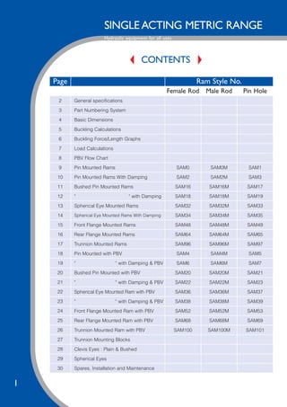
- 1. SINGLE ACTING METRIC RANGE Hydraulic equipment for all uses 1 CONTENTS Page Ram Style No. Female Rod Male Rod Pin Hole 2 General specifications 3 Part Numbering System 4 Basic Dimensions 5 Buckling Calculations 6 Buckling Force/Length Graphs 7 Load Calculations 8 PBV Flow Chart 9 Pin Mounted Rams SAM0 SAM0M SAM1 10 Pin Mounted Rams With Damping SAM2 SAM2M SAM3 11 Bushed Pin Mounted Rams SAM16 SAM16M SAM17 12 " " with Damping SAM18 SAM18M SAM19 13 Spherical Eye Mounted Rams SAM32 SAM32M SAM33 14 Spherical Eye Mounted Rams With Damping SAM34 SAM34M SAM35 15 Front Flange Mounted Rams SAM48 SAM48M SAM49 16 Rear Flange Mounted Rams SAM64 SAM64M SAM65 17 Trunnion Mounted Rams SAM96 SAM96M SAM97 18 Pin Mounted with PBV SAM4 SAM4M SAM5 19 " " with Damping & PBV SAM6 SAM6M SAM7 20 Bushed Pin Mounted with PBV SAM20 SAM20M SAM21 21 " " with Damping & PBV SAM22 SAM22M SAM23 22 Spherical Eye Mounted Ram with PBV SAM36 SAM36M SAM37 23 " " with Damping & PBV SAM38 SAM38M SAM39 24 Front Flange Mounted Ram with PBV SAM52 SAM52M SAM53 25 Rear Flange Mounted Ram with PBV SAM68 SAM68M SAM69 26 Trunnion Mounted Ram with PBV SAM100 SAM100M SAM101 27 Trunnion Mounting Blocks 28 Clevis Eyes : Plain & Bushed 29 Spherical Eyes 30 Spares, Installation and Maintenance
- 2. SINGLE ACTING METRIC RANGE Hydraulic equipment for all uses GENERAL SPECIFICATIONS 2 This catalogue covers our range of Standard Single Acting Metric rams. These rams utilise a welded construction and are ideal for heavy industrial use. Combined with our company policy of 100% product testing and years of experience, we produce a comparatively low cost product on short lead times with no compromise on quality. This catalogue covers only a small part of the wide range of rams that we produce, if you require a product not listed, or to a modified specification please contact the sales office who will be happy to advise you. Options available on request include:- Stainless steel piston rods, marine specification, telescopic, spring return, low friction and chemically resistant seals, limit switches, position transducers and two pack epoxy paint finish. NOTE 1 Maximum pressure rating should not be exceeded, allowance must be made for pulsation and pressure peaks. The customer must ensure that damping pressures do not exceed the maximum pressure rating. NOTE 2 For use with other fluids please contact our sales office. To ensure that testing is carried out with the correct grade of fluid and that all materials are compatible, please state the fluid type when making an order. If no fluid type is specified mineral oil will be assumed. The information contained in the publication is for guidance only . We reserve the right to make changes without notice. The responsibility for checking calculations, formulae, graphs and tables lies with the customer. The vendor will accept no responsibility for any loss or accident howsoever caused. Certified drawings are available on request. Maximum pressure rating (see note 1) 207 Bar (3000 PSI) Test pressure 310 Bar (4500 PSI) Maximum rod velocity 0.5 m/s Fluid temperature range -10 to +90 degrees C Ambient temperature range -10 to +90 degrees C Filtration requirement 25 micron abs, (recommended min.) Fluid specification Mineral Oil DIN51524+51525 HL, H-LP & HV ISO HM (see note 2) Fluid viscosity 5 to 200 cSt Rod finish 20 micron hard chromium plate min Ra.=0.4
- 3. SINGLE ACTING METRIC RANGE Hydraulic equipment for all uses 3 PART NUMBERING SYSTEM Single Acting Metric ram style How our part numbering system works: example: 100-70-SAM0-0250 BORE & ROD DIAMETER in mm 25 - 19 = 25mm bore, 19mm rod 32 - 25 = 32mm bore, 25mm rod 40 - 28 = 40mm bore, 28mm rod 50 - 40 = 50mm bore, 40mm rod 63 - 40 = 63mm bore, 40mm rod 80 - 50 = 80mm bore, 50mm rod 100 - 70 = 100mm bore, 70mm rod 125 - 90 = 125mm bore, 90mm rod STROKE in mm Refer to data sheets and buckling calculations for maximum values. WITHOUT PBV WITH PBV Type of Mounting Male Rod End Female Rod End Pinhole In Rod End Male Rod End Female Rod End Pinhole In Rod End Pin Mounted SAM0M SAM0 SAM1 SAM4M SAM4 SAM5 Pin Mounted with Damping SAM2M SAM2 SAM3 SAM6M SAM6 SAM7 Bushed SAM16M SAM16 SAM17 SAM20M SAM20 SAM21 Bushed with Damping SAM18M SAM18 SAM19 SAM22M SAM22 SAM23 Spherical Eye SAM32M SAM32 SAM33 SAM36M SAM36 SAM37 Spherical Eye with Damping SAM34M SAM34 SAM35 SAM38M SAM38 SAM39 Front Flange SAM48M SAM48 SAM49 SAM52M SAM52 SAM53 Rear Flange SAM64M SAM64 SAM65 SAM68M SAM68 SAM69 Trunnion SAM96M SAM96 SAM97 SAM100M SAM100 SAM101
- 4. SINGLE ACTING METRIC RANGE Hydraulic equipment for all uses 4 BASIC DIMENSIONS The dimensions on this page are common to all the following single acting rams. 25 & 32 bore rams complete with PBV have 3/8” ports Type No. Bore Ø Rod Ø Thrust Area cm2 Pull Area cm2 a c Ø n Pin n Thrd t BSP * u w y x 25-19-SAM_ 25 19 5.0 2.1 10 38 13 10 1/4” 22 25 25 M10x1.50 32-25-SAM_ 32 25 8.0 3.1 11 39 14 12 1/4” 22 25 30 M12x1.75 40-28-SAM_ 40 28 12.6 6.4 14 50 17 14 3/8” 25 30 42 M16x2.00 50-40-SAM_ 50 40 19.6 7.1 18 60 22.5 15.5 3/8” 25 40 48 M20x1.50 63-40-SAM_ 63 40 31.2 18.6 18 73 28 16 3/8” 25 45 58 M24x2.00 80-50-SAM_ 80 50 50.2 30.6 25 95 33 18 3/8” 25 55 68 M30x2.00 100-70-SAM_ 100 70 78.5 40.0 35 115 45 22 1/2” 30 75 80 M39x3.00 125-90-SAM_ 125 90 122.7 59.1 40 145 60 24 1/2” 30 90 86 M45x3.00
- 5. SINGLE ACTING METRIC RANGE Hydraulic equipment for all uses 5 BUCKLING CALCULATIONS The safe working load may be determined from the formula: The safe Working Load = Buckling Force x c/ FoS Where:- c is a constant determined from the table below. FoS is the required Factor of Safety, we recommend a minimum of 3. Where shock loads are present this should be doubled. The actual force to cause buckling may be determined from the following graphs. Note the solid curves are for rear mountings (SAM0, SAM1, SAM2, SAM3, SAM16, SAM17, SAM32, SAM33, SAM64, SAM65) and the dashed curves are for front flange or front trunnion mounted rams (SAM48, SAM49, SAM96 & SAM97). The extended length refers to the distance between the mounting points of the ram, effectively the extended rod length for front end mounted rams. Both ends rounded e.g. Pin or Trunnion mounted One end fixed, one end rounded e.g. Flange mounted c/w spherical eye One end fixed, one end free e.g. Flange or Foot mounted c=1 c=2 c=0.25
- 6. SINGLE ACTING METRIC RANGE Hydraulic equipment for all uses 6 BUCKLING FORCE / LENGTH GRAPHS
- 7. SINGLE ACTING METRIC RANGE Hydraulic equipment for all uses 7 LOAD CALCULATIONS
- 8. SINGLE ACTING METRIC RANGE Hydraulic equipment for all uses 8 PIPE BREAKVALVE (PBV) FLOW CHART Pipe Break Valves may be installed as a safety device. They may be considered as a flow fuse when oil flow leaving the hydraulic ram exceeds the present flow rate of the valve, such as when a hose has failed the valve automatically closes, stopping oil flow out of the ram, and hence preventing any further descent in the ram. In order to release the valve, oil pressure must be applied to the connection port. Corresponding test conditions:- · Oil type = Shell Tellus 37 · Oil viscosity = 76cSt (10°E) · Ambient temperature = 25°C Note: 25 & 32mm bore rams which are normally supplied with ¼”BSP ports are fitted with 3/8”BSP ports when supplied with integral PBV.
- 9. SINGLE ACTING METRIC RANGE Hydraulic equipment for all uses 9 PIN MOUNTED RAMS Note: If rams are required for angular movements, bushes or spherical end bearings should be considered. All Dimensions in mm. Type No. b Ø f Ø g h Ø j p r s Basic Length (Pin.) Basic Length (Thr.) Stroke Range 25-19-SAM 0/1 38 10.5 29 44.5 13 26 27 10 98 148 95 145 10-400 401-800 32-25-SAM 0/1 45 12.5 20 45 13 25 26 11 97 137 95 135 10-350 351-725 40-28-SAM 0/1 55 17.5 25 55 15 25 30 14 100 150 200 97 147 197 10-457 458-850 851-1350 50-40-SAM 0/1 70 20.5 32 70 0 35 15 18 115 165 215 108 158 208 10-500 501-1000 1001-1500 63-40-SAM 0/1 80 25.4 40 85 0 30 14 18 120 170 220 108 158 208 10-610 611-1000 1001-1500 80-50-SAM 0/1 100 30.5 48 100 4 40 22 25 155 205 255 140 190 240 10-600 601-1100 1101-1600 100-70-SAM 0/1 130 40.5 62 130 11 52 30 35 185 235 285 162 212 262 10-650 651-1150 1151-1650 125-90-SAM 0/1 150 50.5 72 150 15 50 35 43 233 313 393 197 277 357 10-750 751-1500 1501-2200
- 10. SINGLE ACTING METRIC RANGE Hydraulic equipment for all uses 10 PIN MOUNTED RAMS with DAMPING Note: Damping must be adjusted to ensure excessive impulse pressures are not induced. Type No. b Ø f Ø g h Ø j p r s Damping Length Basic Length (Pin.) Basic Length (Thr.) Stroke Range 25-19-SAM 2/3 45 10.5 20.5 44.5 15 26 29 10 15 121 171 118 168 10-400 401-800 32-25-SAM 2/3 45 12.5 20 45 16 25 28 11 15 122 162 120 160 10-350 351-725 40-28-SAM 2/3 55 17.5 25 55 20 25 33 14 25 113 163 213 110 160 210 10-457 458-850 851-1350 50-40-SAM 2/3 70 20.5 32 70 23 35 36 18 25 145 195 245 138 188 238 10-500 501-1000 1001-1500 63-40-SAM 2/3 80 25.4 40 85 28 30 44 18 25 158 208 258 146 196 246 10-610 611-1000 1001-1500 80-50-SAM 2/3 95 30.5 48 100 30 40 45 25 25 181 231 281 166 216 266 10-600 601-1100 1101-1600 100-70-SAM 2/3 115 40.5 57.5 130 40 52 57 35 25 224 274 324 201 251 301 10-650 651-1150 1151-1650 125-90-SAM 2/3 150 50.5 75 150 45 50 64 43 25 298 378 458 262 342 422 10-750 751-1500 1501-2200 All Dimensions in mm.
- 11. SINGLE ACTING METRIC RANGE Hydraulic equipment for all uses 11 BUSHED PIN MOUNTED RAMS Bushed pin hole to suit f7 tolerance pins. All Dimensions in mm. Type No. b Ø f Ø g h Ø j p r s Basic Length (Pin.) Basic Length (Thr.) Stroke Range 25-19-SAM 16/17 38 10 29 44.5 13 26 27 10 98 148 95 145 10-400 401-800 32-25-SAM 16/17 45 12 20 45 13 25 26 11 97 137 95 135 10-350 351-725 40-28-SAM 16/17 55 17 25 55 15 25 30 14 100 150 200 97 147 197 10-457 458-850 851-1350 50-40-SAM 16/17 70 20 32 70 0 35 15 18 115 165 215 108 158 208 10-500 501-1000 1001-1500 63-40-SAM 16/17 80 25 40 85 0 30 17 18 120 170 220 108 158 208 10-610 611-1000 1001-1500 80-50-SAM 16/17 100 30 48 100 4 40 22 25 155 205 255 140 190 240 10-600 601-1100 1101-1600 100-70-SAM 16/17 130 40 62 130 11 52 30 35 185 235 285 162 212 262 10-650 651-1150 1151-1650 125-90-SAM 16/17 150 50 75 150 15 50 35 43 233 313 393 197 277 357 10-750 751-1500 1501-2200
- 12. SINGLE ACTING METRIC RANGE Hydraulic equipment for all uses 12 BUSHED PIN MOUNTED RAMS with DAMPING Bushed pin holes to suit f7 toleranced pins. Type No. b Ø f Ø g h Ø j p r s Damping Length Basic Length (Pin.) Basic Length (Thr.) Stroke Range 25-19-SAM 18/19 45 10 20.5 44.5 15 26 29 10 15 121 171 118 168 10-400 401-800 32-25-SAM 18/19 45 12 20 45 16 25 28 11 15 122 162 120 160 10-350 351-725 40-28-SAM 18/19 55 17 25 55 20 25 33 14 25 113 163 213 110 160 210 10-457 458-850 851-1350 50-40-SAM 18/19 70 20 32 70 23 35 36 18 25 145 195 245 138 188 238 10-500 501-1000 1001-1500 63-40-SAM 18/19 80 25 40 85 28 30 44 18 25 158 208 258 146 196 246 10-610 611-1000 1001-1500 80-50-SAM 18/19 95 30 48 100 30 40 45 25 25 181 266 351 166 251 336 10-600 601-1100 1101-1601 100-70-SAM 18/19 115 40 57.5 130 40 52 57 35 25 224 274 324 201 251 301 10-650 651-1150 1151-1650 125-90-SAM 18/19 150 50 75 150 45 50 64 43 25 293 378 458 262 342 422 10-750 751-1500 1501-2200 All Dimensions in mm.
- 13. SINGLE ACTING METRIC RANGE Hydraulic equipment for all uses 13 SPHERICAL EYE MOUNTED RAMS Type No. b Ø f Ø g h Ø j p q x z Basic Length (Pin.) Basic Length (Thr.) Stroke Range 25-19-SAM 32/33 38 10 29 44.5 39 26 15 9 24 124 274 121 171 10-400 401-800 32-25-SAM 32/33 45 12 20 45 43 25 17 10 27 125 165 123 163 10-350 351-725 40-28-SAM 32/33 55 17 25 55 53 25 23 14 35 133 183 233 130 180 230 10-457 458-850 851-1350 50-40-SAM 32/33 70 20 28 70 54 35 26.5 16 38 168 218 268 161 211 261 10-500 501-1000 1001-1500 63-40-SAM 32/33 75 25 37.5 85 63 30 32 20 45 183 233 283 171 221 271 10-610 611-1000 1001-1500 80-50-SAM 32/33 95 30 48 100 72 40 36.5 22 51 219 269 319 204 254 304 10-600 601-1100 1101-1600 100-70-SAM 32/33 115 40 57.5 130 94 52 46 28 69 267 317 367 244 294 344 10-650 651-1150 1151-1650 125-90-SAM 32/33 150 50 72 150 106 50 56 35 88 325 405 485 289 369 449 10-750 751-1500 1501-2200 All Dimensions in mm.
- 14. SINGLE ACTING METRIC RANGE Hydraulic equipment for all uses 14 SPHERICAL EYE MOUNTED RAMS with DAMPING Type No. b Ø f Ø g h Ø j p q x z Damped Length Basic Length (Pin.) Basic Length (Thr.) Stroke Range 25-19-SAM 34/35 38 10 29 44.5 39 26 15 9 24 15 144 194 141 191 10-400 401-800 32-25-SAM 34/35 45 12 20 45 43 25 17 10 27 15 149 189 147 197 10-350 351-725 40-28-SAM 34/35 55 17 25 55 53 25 23 14 35 25 147 197 247 144 294 244 10-457 458-850 851-1350 50-40-SAM 34/35 70 20 28 70 54 35 26.5 16 38 25 186 236 286 179 229 279 10-500 501-1000 1001-1500 63-40-SAM 34/35 76 25 37.5 85 65 30 32 20 45 25 197 247 297 185 235 285 10-610 611-1000 1001-1500 80-50-SAM 34/35 95 30 48 100 72 40 36.5 22 51 25 219 269 319 204 254 304 10-600 601-1100 1101-1600 100-70-SAM 34/35 115 40 57.5 130 89 52 46 28 69 25 268 318 368 245 295 345 10-650 651-1150 1151-1650 125-90-SAM 34/35 150 50 75 150 110 50 56 35 88 25 360 440 520 324 404 484 10-750 751-1500 1501-2200 All Dimensions in mm.
- 15. SINGLE ACTING METRIC RANGE Hydraulic equipment for all uses 15 FRONT FLANGE MOUNTED RAMS Type No. d f Ø i k n (Pin.) n (Thr.) v Ø Basic Length Stroke Range 25-19-SAM 48/49 10 6.35 60 45 13 10 47 80 130 10-400 401-800 32-25-SAM 48/49 18 9 70 50 14 12 50 96 136 10-350 351-725 40-28-SAM 48/49 20 8.5 80 60 17 14 60 87 137 187 10-457 458-850 851-1350 50-40-SAM 48/49 23 10.5 90 65 22 15 72 101 151 201 10-500 501-1000 1001-1500 63-40-SAM 48/49 23 12.5 114 80 28 16 82 97 147 197 10-610 611-1000 1001-1500 80-50-SAM 48/49 23 16.5 130 100 33 18 110 121 171 221 10-400 401-750 751-1100 100-70-SAM 48/49 28 21 160 120 45 22 130 142 192 242 10-650 651-1150 1151-1650 125-90-SAM 48/49 35 25 200 150 60 24 160 166 246 326 10-1000 1001-1600 1601-2200
- 16. SINGLE ACTING METRIC RANGE Hydraulic equipment for all uses 16 REAR FLANGE MOUNTED RAMS Type No. d f Ø h Ø i j k p Basic Length (Pin.) Basic Length (Thr.) Stroke Range 25-19-SAM 64/65 10 6.35 44.5 60 19 45 26 99 149 96 146 10-400 401-800 32-25-SAM 64/65 18 9 45 70 20 50 25 122 162 120 160 10-350 351-725 40-28-SAM 64/65 20 8.5 55 80 21 60 25 126 176 226 123 173 223 10-457 458-850 851-1350 50-40-SAM 64/65 23 10.5 70 90 21 65 35 159 209 259 145 195 245 10-500 501-1000 1001-1500 63-40-SAM 64/65 23 12.5 85 114 22 80 30 165 215 265 153 203 253 10-610 611-1000 1001-1500 80-50-SAM 64/65 23 16.5 100 130 21 100 40 193 243 293 178 228 278 10-600 601-1100 1101-1600 100-70-SAM 64/65 28 21 130 160 25 120 52 226 276 326 203 253 303 10-650 651-1150 1151-1650 125-90-SAM 64/65 35 25 150 200 28 150 50 276 356 436 240 320 400 10-750 751-1500 1501-2200 All Dimensions in mm.
- 17. SINGLE ACTING METRIC RANGE Hydraulic equipment for all uses 17 TRUNNION MOUNTED RAM Type No. c d f Ø L n (Pin.) n (Thr.) v Basic Length Stroke Range 25-19-SAM 96/97 50 30 10 16 28 26 50 73 123 10-400 401-800 32-25-SAM 96/97 55 38 12 18 33 31 55 77 117 10-350 351-725 40-28-SAM 96/97 65 34 17 20 34 31 65 71 121 171 10-457 458-850 851-1350 50-40-SAM 96/97 80 48 20 25 46 39 80 92 142 192 10-500 501-1000 1001-1500 63-40-SAM 96/97 100 34 25 35 45 33 95 80 130 180 10-610 611-1000 1001-1500 80-50-SAM 96/97 120 38 30 45 52 37 120 102 152 202 10-400 401-750 751-1100 100-70-SAM 96/97 140 52 40 50 71 48 140 116 166 216 10-650 651-1150 1151-1650 125-90-SAM 96/97 180 66 50 60 93 57 180 133 213 293 10-1000 1001-1600 1601-2200 All Dimensions in mm.
- 18. SINGLE ACTING METRIC RANGE Hydraulic equipment for all uses 18 PIN MOUNTED RAMS with PBV Type No. b f h j m p r s Basic Length (Pin.) Basic Length (Thr.) Stroke Range 25-19-SAM 4/5 38 10.5 44.5 19 20 26 30 10 101 151 98 148 10-400 401-800 32-25-SAM 4/5 45 12.5 45 22 15 25 35 11 107 147 105 145 10-350 351-725 40-28-SAM 4/5 55 17.5 55 17 29 25 31 14 100 150 200 97 147 197 10-457 458-850 851-1350 50-40-SAM 4/5 70 20.5 70 20 24 35 38 18 135 185 235 128 178 228 10-500 501-1000 1001-1500 63-40-SAM 4/5 80 25.4 85 14 27 30 30 18 137 187 237 125 175 225 10-610 611-1000 1001-1500 80-50-SAM 4/5 100 30.5 100 4 22 40 22 25 155 205 255 140 190 240 10-600 601-1100 1101-1600 100-70-SAM 4/5 130 40.5 130 8 28 52 27 35 185 235 285 162 212 262 10-650 651-1150 1151-1650 125-90-SAM 4/5 150 50.5 150 15 26 50 37 43 233 313 393 197 277 357 10-750 751-1500 1501-2200 All Dimensions in mm.
- 19. SINGLE ACTING METRIC RANGE Hydraulic equipment for all uses 19 PIN MOUNTED RAMS with DAMPING & PBV Type No. b f Ø h Ø j m p r s Basic Length (Pin.) Basic Length (Thr.) Stroke Range 25-19-SAM 6/7 45 10.5 44.5 19 28 26 34 10 128 178 125 175 10-400 401-800 32-25-SAM 6/7 45 12.5 45 22 28 25 37 11 132 172 130 170 10-350 351-725 40-28-SAM 6/7 55 17.5 55 24 28 25 38 14 121 171 221 118 168 218 10-457 458-850 851-1350 50-40-SAM 6/7 70 20.5 70 20 24 35 38 18 145 195 245 138 188 238 10-500 501-1000 1001-1500 63-40-SAM 6/7 80 25.4 85 28 16 30 44 18 158 208 258 146 196 246 10-610 611-1000 1001-1500 80-50-SAM 6/7 100 30.5 100 30 15 40 47 25 181 231 281 166 216 266 10-600 601-1100 1101-1600 100-70-SAM 6/7 130 40.5 130 36 12 52 56 35 220 270 320 197 247 297 10-650 651-1150 1151-1650 125-90-SAM 6/7 150 50.5 150 46 13 50 56 43 298 378 458 262 342 422 10-750 751-1500 1501-2200 All Dimensions in mm.
- 20. SINGLE ACTING METRIC RANGE Hydraulic equipment for all uses 20 BUSHED PIN MOUNTED RAMS with PBV Type No. b f Ø h Ø j m p r s Basic Length (Pin.) Basic Length (Thr.) Stroke Range 25-19-SAM 20/21 38 10 44.5 19 20 26 32 10 101 151 98 148 10-400 401-800 32-25-SAM 20/21 45 12 45 22 15 25 37 11 110 150 108 148 10-350 351-725 40-28-SAM 20/21 55 17 55 17 29 25 32 14 100 150 200 97 147 197 10-457 458-850 851-1350 50-40-SAM 20/21 70 20 70 20 24 35 40 18 135 185 235 128 178 228 10-500 501-1000 1001-1500 63-40-SAM 20/21 80 25 85 14 27 30 30 18 137 187 237 125 175 225 10-610 611-1000 1001-1500 80-50-SAM 20/21 100 30 100 4 22 40 22 25 155 205 255 140 190 240 10-600 601-1100 1101-1600 100-70-SAM 20/21 130 40 130 8 28 52 30 35 185 235 285 162 212 262 10-650 651-1150 1151-1650 125-90-SAM 20/21 150 50 150 15 26 50 37 43 233 313 393 197 277 357 10-750 751-1500 1501-2200 All Dimensions in mm. Bushed pin holes to suit f7 tolerance pins.
- 21. SINGLE ACTING METRIC RANGE Hydraulic equipment for all uses 21 BUSHED PIN MOUNTED RAMS with DAMPING & PBV Type No. b f Ø h Ø j m p r s Basic Length (Pin.) Basic Length (Thr.) Stroke Range 25-19-SAM 22/23 45 10 44.5 19 28 26 34 10 128 178 125 175 10-400 401-800 32-25-SAM 22/23 45 12 45 22 28 25 37 11 132 172 130 170 10-350 351-725 40-28-SAM 22/23 55 17 55 24 28 25 38 14 121 171 221 118 168 218 10-457 458-850 851-1350 50-40-SAM 22/23 70 20 70 20 24 35 38 18 145 195 245 138 188 238 10-500 501-1000 1001-1500 63-40-SAM 22/23 80 25 85 28 15 30 44 18 158 208 258 146 196 246 10-610 611-1000 1001-1500 80-50-SAM 22/23 100 30 100 30 15 40 47 25 181 231 281 166 216 266 10-600 601-1100 1101-1600 100-70-SAM 22/23 130 40 130 36 12 52 56 35 220 270 320 197 247 297 10-650 651-1150 1151-1650 125-90-SAM 22/23 150 50 150 46 13 50 56 43 298 378 458 262 342 422 10-750 751-1500 1501-2200 All Dimensions in mm. Bushed pin holes to suit f7 tolerance pins.
- 22. SINGLE ACTING METRIC RANGE Hydraulic equipment for all uses 22 SPHERICAL EYE MOUNTED RAMS with PBV Type No. b Ø f Ø h Ø j m p q x z Basic Length (Pin.) Basic Length (Thr.) Stroke Range 25-19-SAM 36/37 38 10 45 46 19 26 15 9 24 135 185 132 182 10-400 401-800 32-25-SAM 36/37 45 12 45 48 15 25 17 10 27 135 117 133 117 10-350 351-725 40-28-SAM 36/37 55 17 55 56 15 25 23 14 35 144 194 244 141 191 241 10-457 458-850 851-1350 50-40-SAM 36/37 70 20 70 59 24 35 26.5 16 38 175 225 275 168 218 268 10-500 501-1000 1001-1500 63-40-SAM 36/37 76 25 85 65 22 30 32 20 45 190 240 290 178 223 278 10-610 611-1000 1001-1500 80-50-SAM 36/37 100 30 100 69 15 40 36.5 22 51 219 269 319 204 254 304 10-600 601-1100 1101-1600 100-70-SAM 36/37 115 40 130 94 12 52 46 28 69 267 317 367 244 294 344 10-650 651-1150 1151-1650 125-90-SAM 36/37 150 50 150 113 12 50 56 35 88 333 413 493 297 377 457 10-750 751-1500 1501-2200 All Dimensions in mm.
- 23. SINGLE ACTING METRIC RANGE Hydraulic equipment for all uses 23 SPHERICAL EYE MOUNTED RAMS with DAMPING & PBV Type No. b Ø f Ø h Ø j m p q x z Damped Length Basic Length (Pin.) Basic Length (Thr.) Stroke Range 25-19-SAM 38/39 45 10 45 46 28 26 15 9 24 15 155 205 152 202 10-400 401-800 32-25-SAM 38/39 45 12 45 49 28 25 17 10 27 15 159 199 157 197 10-350 351-725 40-28-SAM 38/39 55 17 55 56 28 25 23 14 35 25 153 203 253 150 200 250 10-457 458-850 851-1350 50-40-SAM 38/39 70 20 70 59 24 35 26.5 16 38 25 186 236 286 179 229 279 10-500 501-1000 1001-1500 63-40-SAM 38/39 76 25 85 65 22 30 32 20 45 25 197 247 297 185 235 285 10-610 611-1000 1001-1500 80-50-SAM 38/39 100 30 100 69 15 40 36.5 22 51 25 219 269 319 204 254 304 10-650 651-1150 1151-1650 100-70-SAM 38/39 115 40 130 94 12 52 46 28 69 25 276 326 376 253 323 353 10-650 651-1150 1151-1650 125-90-SAM 38/39 150 50 150 113 13 50 56 35 88 25 369 449 529 333 413 493 10-750 751-1500 1501-2200 All Dimensions in mm.
- 24. SINGLE ACTING METRIC RANGE Hydraulic equipment for all uses 24 FRONT FLANGE MOUNTED RAMS with PBV Type No. d f Ø i k m n (Pin.) n (Thr.) v Ø Basic Length Stroke Range 25-19-SAM 52/53 10 6.35 60 45 23 13 10 47 113 163 10-400 401-800 32-25-SAM 52/53 18 9 70 50 23 14 12 50 111 151 10-350 351-725 40-28-SAM 52/53 20 8.5 80 60 23 17 14 60 126 176 226 10-457 458-850 851-1350 50-40-SAM 52/53 23 10.5 90 65 15 22 15 70 130 180 230 10-500 501-1000 1001-1500 63-40-SAM 52/53 23 12.5 114 80 19 28 16 82 131 181 231 10-610 611-1000 1001-1500 80-50-SAM 52/53 23 16.5 130 100 15 33 18 110 150 200 250 10-400 401-750 751-1100 100-70-SAM 52/53 28 21 160 120 18 45 22 130 164 214 264 10-650 651-1150 1151-1650 125-90-SAM 52/53 35 25 200 150 18 60 24 160 193 273 335 10-1000 1001-1600 1601-2200 All Dimensions in mm.
- 25. SINGLE ACTING METRIC RANGE Hydraulic equipment for all uses 25 REAR FLANGE MOUNTED RAMS with PBV Type No. d f Ø h Ø i j k m p Basic Length (Pin.) Basic Length (Thr.) Stroke Range 25-19-SAM 68/69 10 6.35 44.5 60 22 45 19 26 121 171 118 168 10-400 401-800 32-25-SAM 68/69 18 9 45 70 27 50 15 25 133 183 131 181 10-350 351-725 40-28-SAM 68/69 20 8.5 55 80 27 60 15 25 135 185 235 132 182 232 10-457 458-850 851-1350 50-40-SAM 68/69 23 10.5 70 90 21 65 24 35 160 210 260 153 203 253 10-500 501-1000 1001-1500 63-40-SAM 68/69 23 12.5 85 114 20 80 22 30 168 218 268 156 206 256 10-610 611-1000 1001-1500 80-50-SAM 68/69 23 16.5 100 130 28 100 15 40 201 251 301 186 236 286 10-600 601-1100 1101-1600 100-70-SAM 68/69 28 21 130 160 25 120 18 52 226 276 326 203 253 303 10-650 651-1150 1151-1650 125-90-SAM 68/69 35 25 150 200 28 150 12 50 280 360 440 244 324 404 10-750 751-1500 1501-2200 All Dimensions in mm.
- 26. SINGLE ACTING METRIC RANGE Hydraulic equipment for all uses 26 TRUNNION MOUNTED RAMS with PBV All Dimensions in mm. Type No. c d f Ø l m n (Pin.) n (Thr.) v Ø Basic Length Stroke Range 25-19-SAM 100/101 50 30 10 16 23 28 25 50 106 156 10-400 401-800 32-25-SAM 100/101 55 38 12 18 23 33 31 55 115 155 10-350 351-725 40-28-SAM 100/101 65 34 17 20 23 34 31 65 109 259 309 10-457 458-850 851-1350 50-40-SAM 100/101 80 48 20 25 15 46 39 80 121 171 221 10-500 501-1000 1001-1500 63-40-SAM 100/101 100 34 25 35 19 45 33 95 114 164 214 10-610 611-1000 1001-1500 80-50-SAM 100/101 120 38 30 45 15 52 37 120 131 181 231 10-400 401-750 751-1100 100-70-SAM 100/101 140 52 40 50 18 71 48 140 138 188 238 10-650 651-1150 1151-1650 125-90-SAM 100/101 180 66 50 60 18 93 57 180 160 240 320 10-1000 1001-1600 1601-2200
- 27. SINGLE ACTING METRIC RANGE Hydraulic equipment for all uses 27 TRUNNION MOUNTING BLOCKS All Dimensions in mm. Part No. (pair) a Ø b d f g h j k 25-16-0350 10 30 30 15 12 22 M8 15 32-20-0351 12 35 35 18 13 25 M10 18 40-28-0353 17 40 40 20 18 30 M12 18 50-28-0353 20 45 45 24 20 32 M16 22 63-40-0354 25 55 55 33 25 38 M20 25 80-50-0351 30 65 65 43 30 45 M24 30 100-70-0354 40 80 80 48 38 55 M30 35 125-70-0350 50 100 100 58 50 70 M36 50
- 28. SINGLE ACTING METRIC RANGE Hydraulic equipment for all uses 28 CLEVIS EYE, PLAIN & BUSHED All Dimensions in mm. Part No. without Bush # Part No. with Bush * Lock Nut Part No. a # Ø a * Ø b c d e f g h j k 25-16-0270 25-16-0271 25-16-0480 10.5 10 13 35 30 20 M10x1.5 45 27 6 17 32-20-0271 32-20-0272 32-20-0480 12.5 12 20 42 40 25 M12x1.75 55 32 7 19 40-28-0274 40-28-0275 40-28-0482 17.5 17 20 60 40 40 M16x2 80 45 9 24 50-28-1270 50-28-1271 50-28-0480 20.5 20 23 68 45 45 M20x1.5 90 50 9 30 63-40-1275 63-40-1276 63-40-0482 25.4 25 26 80 57 57 M24x2 108 60 10 36 80-50-1271 80-50-1273 80-50-0455 30.5 30 20 93 63.5 63.5 M30x2 125 70 12 45 100-70-1276 100-70-1277 100-70-0452 40.5 40 40 115 80 80 M39x3 155 90 16 55 125-70-0271 125-70-0272 125-70-0451 50.5 50 52 135 114 114 M45x3 190 120 18 65
- 29. SINGLE ACTING METRIC RANGE Hydraulic equipment for all uses 29 SPHERICAL EYES All Dimensions in mm. End Eye Part No. Lock Nut Part No. a h5 Ø b d e f g h j k m n p 25-16-0436 25-16-0480 10 9 M10x1.5 33 48 7 15 27 26 14 6 17A/F 32-20-0431 32-20-0480 12 10 M12x1.75 38 54 8 17 31 28 16 7 19A/F 40-28-0439 40-28-0482 17 14 M16x2 47 69 11 22.5 41 36 20 9 24A/F 50-28-0438 50-28-0480 20 16 M20x1.5 49 78 13 25.5 47 43 23 9 30A/F 63-40-0433 63-40-0482 25 20 M24x2 56 94 17 30 55 53 27 10 36A/F 80-50-0437 80-50-0455 30 22 M30x2 62 110 19 35 65 65 30 12 45DIA 100-70-0438 100-70-0452 40 28 M39x3 85 150 23 48 88 86 44 16 55DIA 125-70-0437 125-70-0451 50 35 M45x3 104 185 30 61 111 104 58 18 63.5DIA
- 30. SINGLE ACTING METRIC RANGE Hydraulic equipment for all uses 30 SPARES We supply an extensive range of hydraulic spares for every item that we have manufactured, including piston rods, cylinders and seal kits. Please ensure that you always state the ram serial number when ordering spares. This will be stamped onto the bottom end or around the flange or trunnion. INSTALLATION & MAINTENANCE 1. STORAGE Port plug must always be left in until pipe connections are to be made. Rams should be oiled and stored in a clean dry atmosphere. They should be vertical to prevent seal set and should not be stored for in excess of 24 months without manufacturers overhaul. 2. INSTALLATION Piping must be thoroughly cleaned and deburred before connection. Sealing agents such as hemp and putty must not be used. Ensure all moving surfaces are correctly lubricated. Rams must be installed free from bending forces and side loads. Initially the system should be cycled at low pressure. All air must be bled from the system to ensure satisfactory function. This may be carried out by cracking pipe joints at the highest points in the system. Only agreed types and grades of fluids may be used. 3. MAINTENANCE Good fluid condition is essential for maximum ram life. Contaminated or aged fluid should be replaced, not topped up. If the rod or bore shows signs of marking the unit should be returned to the manufacturer for overhaul. Seal life is dependent on working conditions, particularly the fluid condition, working atmosphere, temperature and speed. Impulse and shock pressures are especially inclined to reduce seal life. Ensure system pressure is dumped and loads are otherwise supported before attempting maintenance. Rams should be thoroughly cleaned prior to reassembly. Abrasive dust and chemicals should not be allowed on, or around, the piston rod as this will advance seal wear and may initiate rod corrosion.