SlideShare une entreprise Scribd logo
1  sur  7
Télécharger pour lire hors ligne
International Journal of Engineering Research and Development
e-ISSN : 2278-067X, p-ISSN : 2278-800X, www.ijerd.com
Volume 2, Issue 5 (July 2012), PP. 71-77


     Wearable Wireless Sensor Network for human limbs motion
                        V. Naveen Raja1, P M Francis2, G. Chennakesavulu3
                 1
                     M.Tech Student, Rll.No: 10H91D6802,VLSI & ES, Gokul Institute of Tech&Science,Bobbili
                                        2
                                          Asst.Prof,Gokul Institute of Tech&Science,Bobbili.
                               3
                                 Asst.Prof, Priyadarshini Institute of Tech & Science, Chintalapudi.


Abstract—Most of the existing systems require wiring that restrains the natural movement. To overcome this limitation,
a wearable wireless sensor network using accelerometers have been developed in this project. In this project, a wearable
wireless sensor system is proposed to overcome this limitation. The wireless feature enables the unrestrained motion of
the human body as opposed to a wired monitoring device and makes the system truly portable. This will also allow the
system to be deployed in a cluttered home environment. The small form factor and lightweight feature of the sensor nodes
also allow easy attachment to the limbs. This technology also used in sports technology, in this field we know about the
players’ behaviour. In our project we will introduce the MEM sensors and FLEX sensors in to medical and sports
applications.

Keywords— MEMs, FLEX, Wireless Sensor.

                                            I.          INTRODUCTION
           Tracking of human motion has attracted significant interest in recent years due to its wide-ranging applications
such as rehabilitation, virtual reality, sports science, medical science and surveillance. In recent years, inertial and magnetic
tracking have attracted much interest as they are source-free approaches unlike the audio and radar that require an emission
source. The development of micro electromechanical system technology and flex sensor technology had also made such
sensors lighter, smaller, and cheaper. Consequently, they are good candidates conducted in patient’s home or office. This
will also reduce the frequency to visit the hospital for patients undergoing physiotherapy. This technology also used in sports
technology, in this field we know about the player’s behaviour. In this project the MEMS sensors and FLEX sensors will be
introduced in to medical and sports applications. The wireless feature enables the unrestrained motion of the human body as
opposed to a wired monitoring device and makes the system truly portable. This will also allow the system to be deployed in
a cluttered home environment. The small form factor and lightweight feature of the sensor nodes also allow easy attachment
to the limbs.

                                          II.          BLOCK DIAGRAM


                                         Figure 1.General configuration of the system


                                                              71
Wearable Wireless Sensor Network for human limbs motion

                                  III.            SERIAL COMMUNICATION
            Serial communication is basically the transmission or reception of data one bit at a time. Today's computers
generally address data in bytes or some multiple thereof. A byte contains 8 bits. A bit is basically either a logical 1 or zero.
Every character on this page is actually expressed internally as one byte.
            The serial port is used to convert each byte to a stream of ones and zeroes as well as to convert a stream of ones
and zeroes to bytes. The serial port contains an electronic chip called a Universal Asynchronous Receiver/Transmitter
(UART) that actually does the conversion. The serial port has many pins. We will discuss the transmit and receive pins first.
Electrically speaking, whenever the serial port sends a logical one (1) a negative voltage is effected on the transmit pin.
Whenever the serial port sends a logical zero (0) a positive voltage is affected. When no data is being sent, the serial port's
transmit pin's voltage is negative (1) and is said to be in a MARK state. Note that the serial port can also be forced to keep
the transmit pin at a positive voltage (0) and is said to be the SPACE or BREAK state. (The terms MARK and SPACE are
also used to simply denote a negative voltage (1) or a positive voltage (0) at the transmit pin respectively).When transmitting
a byte, the UART (serial port) first sends a START BIT which is a positive voltage (0), followed by the data (general 8 bits,
but could be 5, 6, 7, or 8 bits) followed by one or two STOP Bits which is a negative(1) voltage. The sequence is repeated
for each byte sent. When transmitting a character there are other characteristics other than the baud rate that must be known
or that must be setup. These characteristics define the entire interpretation of the data stream. The first characteristic is the
length of the byte that will be transmitted. This length in general can be anywhere from 5 to 8 bits.
            The second characteristic is parity. The parity characteristic can be even, odd, mark, space, or none. If even parity,
then the last data bit transmitted will be a logical 1 if the data transmitted had an even amount of 0 bits. If odd parity, t hen
the last data bit transmitted will be a logical 1 if the data transmitted had an odd amount of 0 bits. If MARK parity, then the
last transmitted data bit will always be a logical 1. If SPACE parity, then the last transmitted data bit will always be a logical
0. If no parity then there is no parity bit transmitted.
            The third characteristic is the amount of stop bits. This value in general is 1 or 2. Assume we want to send the
letter 'A' over the serial port. The binary representation of the letter 'A' is 01000001. Remembering that bits are transmitted
from least significant bit (LSB) to most significant bit (MSB), the bit stream transmitted would be as follows for the line
characteristics 8 bits, no parity, 1 stop bit and 9600 baud. LSB (0 1 0 0 0 0 0 1 0 1) MSB. The above represents (Start Bit)
(Data Bits) (Stop Bit). To calculate the actual byte transfer rate simply divide the baud rate by the number of bits that must
be transferred for each byte of data.
            In the case of the above example, each character requires 10 bits to be transmitted for each character. As such, at
9600 baud, up to 960 bytes can be transferred in one second. The above discussion was concerned with the
"electrical/logical" characteristics of the data stream. We will expand the discussion to line protocol. Serial communication
can be half duplex or full duplex. Full duplex communication means that a device can receive and transmit data at the same
time. Half duplex means that the device cannot send and receive at the same time. It can do them both, but not at the same
time. Half duplex communication is all but out-dated except for a very small focused set of applications. Half duplex serial
communication needs at a minimum two wires, signal ground and the data line. Full duplex serial communication needs at a
minimum three wires, signal ground, transmit data line, and receive data line.
            These signals are the Carrier Detect Signal (CD), asserted by modems to signal a successful connection to another
modem, Ring Indicator (RI), asserted by modems to signal the phone ringing, Data Set Ready (DSR), asserted by modems to
show their presence, Clear To Send (CTS), asserted by modems if they can receive data, Data Terminal Ready (DTR),
asserted by terminals to show their presence, Request To Send (RTS), asserted by terminals if they can receive data. The
section RS232 Cabling describes these signals and how they are connected. The above paragraph alluded to hardware flow
control. Hardware flow control is a method that two connected devices use to tell each other electronically when to send or
when not to send data. A modem in general drops (logical 0) its CTS line when it can no longer receive characters. Note that
hardware flow control requires the use of additional wires. The benefit to this however is crisp and reliable flow control.
Another method of flow control used is known as software flow control. This method requires a simple 3 wire serial
communication link, transmit data, receive data, and signal ground. If using this method, when a device can no longer
receive, it will transmit a character that the two devices agreed on. This character is known as the XOFF character. This
character is generally a hexadecimal 13. When a device can receive again it transmits an XON character that both devices
agreed to. This character is generally a hexadecimal 11.

                                            IV.            FLEX SENSOR
          The Flex Sensor patented technology is based on resistive carbon elements. As a variable printed resistor, the Flex
Sensor achieves great form-factor on a thin flexible substrate. When the substrate is bent, the sensor produces a resistance
output correlated to the bend radius—the smaller the radius, the higher the resistance value. Flex sensors are sensors that
change in resistance depending on the amount of bend on the sensor. They convert the change in bend to electrical resistance
- the more the bend, the more the resistance value. They are usually in the form of a thin strip from 1"-5" long that vary in
resistance from approximately 10 to 50 kilo ohms. They are often used in gloves to sense finger movement.
2.1.      Attributes of FLEX Sensors
       Custom designed to match customer specs
       High level of reliability, consistency, repeatability
       Harsh temperature resistance
       Variety of flexible or stationary surfaces for mounting
       Infinite number of resistance possibilities and bend ratios


                                                               72
Wearable Wireless Sensor Network for human limbs motion

2.2.      TILT ANGLE MEASUREMENT
      The movement of the human arm along sagittal plane, i.e., the plane that bisects the human body into left and right is
investigated. This corresponds to the flexion and extension movements of the forearm and the upper arm. Flexion is a
bending movement in which the relative angle of the joint between the adjacent segments decreases. Extension is a
straightening movement in which the relative angle of the joint between two adjacent segment increases as the joint returns
to the reference anatomical position. For the physical therapist, the range of the elbow motion and shoulder joint of the
patient is of particular interest for monitoring the rehabilitation progress. To capture the arm’s rotational motion, an
accelerometer is integrated to the sensor node as an inclinometer.


                                        Fig: 3. Tilt Angle Measurement in Y-Z Plane

                                V.           TILT/STATIC MEASUREMENT
           Figure 2 shows an accelerometer mounted on the forearm. In the static conditions, i.e., the arm is not moving; the
tilt angle θ of the accelerometer can be determined by measuring the acceleration due to gravity g. The accelerations AY in
the Y -axis and AZ in the Z-axis that are due to gravity can be determined as
                                                   AY =g sin θ --------------(1)
                                                   AZ =g cos θ.------------- (2)
From (1) and (2), the tilt angle θ can be determined as
                                                θ = tan−1 AY/AZ ------------ . (3)
The quadrant of θ can be determined by the sign of AY .The output voltage Vout of the accelerometer is related to the
acceleration Ai of a particular axis (i = Y or Z) by the following relationship:
                                           Vout = Voffset + S × Ai ------------------(4)
Where S = ΔV/Δg is the sensitivity of the accelerometer (in volts per meter per second squared), and Voffset is the offset of
the accelerometer at 0g.
The corresponding ADC value can be expressed as


                                           ---- (5)
Where n is the resolution bits of the ADC (n = 8 in this case), V + REF and V−REF are the reference voltage levels, and Q[ ]
is the quantized function. The accelerometer is ratio metric, i.e., the output voltage and sensitivity linearly scale with the
reference voltage. From (4) and (5), it is observed that the supply induced errors are cancelled in the analog-to-digital
conversion process.
Substituting Vout from (4) into (5), the acceleration Ai is approximately proportional to λi after subtracting an equivalent
ADC offset. As such, (3) can be rewritten as follows:


θ = tan−1[ λY − λY o/ λZ – λZo] --------------(6)
Where λY and λZ are the ADC output values of the accelerometer in the Y - and Z-axes, respectively, and λY o and λZo are the
offsets of the accelerometer at 0g.


                                                             73
Wearable Wireless Sensor Network for human limbs motion


                                  VI.           MICROCHIP MPLAB IDE
           MPLAB Integrated Development Environment (IDE) is a free, integrated toolset for the development of embedded
applications employing Microchip's PIC® and dsPIC® microcontrollers. MPLAB IDE runs as a 32-bit application on MS
Windows®, is easy to use and includes a host of free software components for fast application development and super-
charged debugging. MPLAB IDE also serves as a single, unified graphical user interface for additional Microchip and third
party software and hardware development tools. Moving between tools is a snap, and upgrading from the free software
simulator to hardware debug and programming tools is done in a flash because MPLAB IDE has the same user interface for
all tools.
           The MPLAB IDE software brings an ease of software development previously unseen in the 8/16-bit
microcontroller market.

The MPLAB IDE is a Windows® based application that contains:
     An interface to debugging tools
          simulator
          programmer (sold separately)
          emulator (sold separately)
          in-circuit debugger (sold separately)
     A full-featured editor with colour coded context
     A multiple project manager
     Customizable data windows with direct edit of contents
     High level source code debugging

The MPLAB IDE allows you to:
     Edit your source files (either assembly or C)
     One touch assemble (or compile) and download to PIC micro emulator and simulator tools
     Debug using:
          source files (assembly or C)
          absolute listing file (mixed assembly and C)
          machine code

          MPLAB IDE supports multiple debugging tools in a single development paradigm, from the cost effective
simulators, through low cost in-circuit debuggers, to full-featured emulators. This eliminates the learning curve when
upgrading to tools with increasing flexibility and power.

                               VII.           EXPERIMENTAL RESULTS
         Figure 4 shows the experimental set up of the project. The transmitter and the receiver sections are connected to
PC. The MEMS sensor and the FLEX sensor are connected to the transmitter, transmits the sensed data. Receiver is
connected to the COM port of the computer. It receives the data and sends to the PC via RS232 cable.


                                                           74
Wearable Wireless Sensor Network for human limbs motion


                                              Figure 4: Experimental Set up

           The MEMS sensor shown in figure 6.2 is attached to the forearm of the human as shown in figure 6.3. The FLEX
sensor is attached to the fingers of the human as shown in figure 6.4. These sensors senses the movements of forearm and the
fingers of the human and corresponding analog values are send to the microcontroller.


                                                Figure 4.1: MEMS Sensor


                                     Figure 4.3: MEMS Sensor attached to the human

                                                            75
Wearable Wireless Sensor Network for human limbs motion

           The on chip ADC of the PIC microcontroller converts the analog value to Digital and sends to the RF transceiver
which is then transmitted to the receiver. The receiver receives the data and sends it to the microcontroller which is then
serially transmitted to the PC. The data is displayed on the PC with the help of hyper terminal.


                                Figure 4.2 : FLEX sensor attached to the finger of human

         As the movements of forearm and fingers of human changes, the corresponding values are displayed on the PC as
shown in the figure 6.5.


                                           Figure 4.4: Results displayed on PC

                                      VIII.           FUTURE SCOPE
        An ambulatory and unrestrained measurement system based on a wearable wireless sensor network for tracking the
human arm motion in the sagittal plane has been proposed. The wireless feature enables the unrestrained motion of the
human body as opposed to a wired monitoring device and makes the system truly portable. This allows the system to be


                                                           76
Wearable Wireless Sensor Network for human limbs motion

deployed in a cluttered home environment. The small form factor and lightweight feature of the sensor nodes also allow easy
attachment to the limbs.
          As compared with other existing approaches, the new system is portable and easy to use. It allows the patients to
be monitored without restraint, and rehabilitation can be carried out in a home environment instead of a specialized
laboratory in the hospital. For future work, experiments conducted with stroke patients in collaboration with a hospital are
being planned using the developed system. More tests can also be conducted to investigate the effect of RF interference from
other patient monitoring devices and wireless systems.


                                                          REFERENCES
  [1].    H. Zhou and H. Hu, ―Human motion tracking for rehabilitation—A survey,‖ Biomed. Signal Process. Control, vol. 3, no. 1, pp.
         1–18, Jan. 2008.
  [2].    J.M. Zheng, K.W. Chan, and I. Gibson, ―Virtual reality,‖ IEEE Potentials, vol. 17, no. 2, pp. 20–23, Apr. 1998.
  [3].   D. Jack, R. Boian, A. S. Merians, M. Tremaine, G. C. Burdea, S. V. Adamovich, M. Recce, and H. Poizner, ―Virtual reality -
         enhanced stroke rehabilitation,‖ IEEE Trans. Neural Syst. Rehabil. Eng., vol. 9, no. 3, pp. 308–318, Sep. 2001.
  [4].   D. Fitzgerald, J. Foody, D. Kelly, T. Ward, C. Markham, J. McDonald, and B. Caulfield, ―Development of a wearable motion
         capture suit and virtual reality biofeedback system for the instruction and analysis of sports rehabilitation exercises,‖ in Proc.
         29th Annu. Int. Conf. IEEE EMBS, 2007, pp. 4870–4874.
  [5].   T. B.Moeslund, A. Hilton, and V. Krüger, ―A survey of advances in visionbased human motion capture and analysis,‖ Comput.
         Vis. Image Underst.


                                                                  77

Contenu connexe

Tendances

Microcontroll er based gesture vocalizer
Microcontroll er based gesture vocalizerMicrocontroll er based gesture vocalizer
Microcontroll er based gesture vocalizer
PRADEEP Cheekatla
 
Iaetsd ethernet based intelligent security system
Iaetsd ethernet based intelligent security systemIaetsd ethernet based intelligent security system
Iaetsd ethernet based intelligent security system
Iaetsd Iaetsd
 
Design and Detection of Underground Cable Fault Using Raspberry Pi and IoT Sy...
Design and Detection of Underground Cable Fault Using Raspberry Pi and IoT Sy...Design and Detection of Underground Cable Fault Using Raspberry Pi and IoT Sy...
Design and Detection of Underground Cable Fault Using Raspberry Pi and IoT Sy...
ijtsrd
 
Design of single channel portable eeg
Design of single channel portable eegDesign of single channel portable eeg
Design of single channel portable eeg
ijbesjournal
 
Project intrusion alert
Project intrusion alertProject intrusion alert
Project intrusion alert
arpit1010
 
Electronic Hand Glove for Speed Impaired and Paralyzed Patients
Electronic Hand Glove for Speed Impaired and Paralyzed PatientsElectronic Hand Glove for Speed Impaired and Paralyzed Patients
Electronic Hand Glove for Speed Impaired and Paralyzed Patients
IEEEP Karachi
 
Pc to pc optical fiber communication
Pc to pc optical fiber communicationPc to pc optical fiber communication
Pc to pc optical fiber communication
Padmakar Mangrule
 
Environmental Sensor Network Paper
Environmental Sensor Network PaperEnvironmental Sensor Network Paper
Environmental Sensor Network Paper
Zoey Y. Kang
 

Tendances (20)

Ijetcas14 374
Ijetcas14 374Ijetcas14 374
Ijetcas14 374
 
GSM based elevator alarm and Panic Detection
GSM based elevator alarm and Panic DetectionGSM based elevator alarm and Panic Detection
GSM based elevator alarm and Panic Detection
 
IRJET- Arduino based Single Phase Fault Detection System using IoT
IRJET- Arduino based Single Phase Fault Detection System using IoTIRJET- Arduino based Single Phase Fault Detection System using IoT
IRJET- Arduino based Single Phase Fault Detection System using IoT
 
IRJET- IoT based Fault Finding of an Underground Cable
IRJET-  	  IoT based Fault Finding of an Underground CableIRJET-  	  IoT based Fault Finding of an Underground Cable
IRJET- IoT based Fault Finding of an Underground Cable
 
IRJET- IoT based Cost-Effective Digital Light Meter
IRJET- IoT based Cost-Effective Digital Light MeterIRJET- IoT based Cost-Effective Digital Light Meter
IRJET- IoT based Cost-Effective Digital Light Meter
 
Microcontroll er based gesture vocalizer
Microcontroll er based gesture vocalizerMicrocontroll er based gesture vocalizer
Microcontroll er based gesture vocalizer
 
37 112-1-pb
37 112-1-pb37 112-1-pb
37 112-1-pb
 
Iaetsd ethernet based intelligent security system
Iaetsd ethernet based intelligent security systemIaetsd ethernet based intelligent security system
Iaetsd ethernet based intelligent security system
 
main
mainmain
main
 
RSA Algorithm as a Data Security Control Mechanism in RFID
RSA Algorithm as a Data Security Control Mechanism in RFIDRSA Algorithm as a Data Security Control Mechanism in RFID
RSA Algorithm as a Data Security Control Mechanism in RFID
 
Design and Detection of Underground Cable Fault Using Raspberry Pi and IoT Sy...
Design and Detection of Underground Cable Fault Using Raspberry Pi and IoT Sy...Design and Detection of Underground Cable Fault Using Raspberry Pi and IoT Sy...
Design and Detection of Underground Cable Fault Using Raspberry Pi and IoT Sy...
 
Design of single channel portable eeg
Design of single channel portable eegDesign of single channel portable eeg
Design of single channel portable eeg
 
Project intrusion alert
Project intrusion alertProject intrusion alert
Project intrusion alert
 
conference1final
conference1finalconference1final
conference1final
 
Healthcare Monitoring System by using iSense Device& IOT Platform
Healthcare Monitoring System by using iSense Device& IOT PlatformHealthcare Monitoring System by using iSense Device& IOT Platform
Healthcare Monitoring System by using iSense Device& IOT Platform
 
Gesture vocalizer
Gesture vocalizerGesture vocalizer
Gesture vocalizer
 
IRJET- Underground Cable Fault Distance Locator
IRJET- Underground Cable Fault Distance LocatorIRJET- Underground Cable Fault Distance Locator
IRJET- Underground Cable Fault Distance Locator
 
Electronic Hand Glove for Speed Impaired and Paralyzed Patients
Electronic Hand Glove for Speed Impaired and Paralyzed PatientsElectronic Hand Glove for Speed Impaired and Paralyzed Patients
Electronic Hand Glove for Speed Impaired and Paralyzed Patients
 
Pc to pc optical fiber communication
Pc to pc optical fiber communicationPc to pc optical fiber communication
Pc to pc optical fiber communication
 
Environmental Sensor Network Paper
Environmental Sensor Network PaperEnvironmental Sensor Network Paper
Environmental Sensor Network Paper
 

En vedette (7)

2 - Zoo Information Talk
2 - Zoo Information Talk2 - Zoo Information Talk
2 - Zoo Information Talk
 
Informática:Presentaciones Online
Informática:Presentaciones OnlineInformática:Presentaciones Online
Informática:Presentaciones Online
 
Best practices for developing a strong talent pipeline white paper july 2012
Best practices for developing a strong talent pipeline white paper july 2012Best practices for developing a strong talent pipeline white paper july 2012
Best practices for developing a strong talent pipeline white paper july 2012
 
La Tua Tesi con LCI MICC
 La Tua Tesi con LCI MICC La Tua Tesi con LCI MICC
La Tua Tesi con LCI MICC
 
User manual v1
User manual v1User manual v1
User manual v1
 
4 cs for optimize right diamond value
4 cs for optimize right diamond value4 cs for optimize right diamond value
4 cs for optimize right diamond value
 
Pinterest Basics
Pinterest BasicsPinterest Basics
Pinterest Basics
 

Similaire à IJERD (www.ijerd.com) International Journal of Engineering Research and Development

Paper id 24201478
Paper id 24201478Paper id 24201478
Paper id 24201478
IJRAT
 
unit 4 smartsensors and application.pptx
unit 4 smartsensors and application.pptxunit 4 smartsensors and application.pptx
unit 4 smartsensors and application.pptx
AanshuSingh3
 

Similaire à IJERD (www.ijerd.com) International Journal of Engineering Research and Development (20)

International Journal of Computational Engineering Research(IJCER)
International Journal of Computational Engineering Research(IJCER)International Journal of Computational Engineering Research(IJCER)
International Journal of Computational Engineering Research(IJCER)
 
Serial Communication Interface with Error Detection
Serial Communication Interface with Error DetectionSerial Communication Interface with Error Detection
Serial Communication Interface with Error Detection
 
M010617376
M010617376M010617376
M010617376
 
Chapter 1 introduction haramaya
Chapter 1 introduction haramayaChapter 1 introduction haramaya
Chapter 1 introduction haramaya
 
Complete report on DATA ACQUISITION SCHEME IN WIRELESS SENSOR NETWORK
Complete report on DATA ACQUISITION SCHEME IN WIRELESS SENSOR NETWORKComplete report on DATA ACQUISITION SCHEME IN WIRELESS SENSOR NETWORK
Complete report on DATA ACQUISITION SCHEME IN WIRELESS SENSOR NETWORK
 
UART project report by Tarun Khaneja ( 09034406598 )
UART project report by Tarun Khaneja ( 09034406598 )UART project report by Tarun Khaneja ( 09034406598 )
UART project report by Tarun Khaneja ( 09034406598 )
 
Data Flow in Wireless Sensor Network Protocol Stack by using Bellman-Ford Rou...
Data Flow in Wireless Sensor Network Protocol Stack by using Bellman-Ford Rou...Data Flow in Wireless Sensor Network Protocol Stack by using Bellman-Ford Rou...
Data Flow in Wireless Sensor Network Protocol Stack by using Bellman-Ford Rou...
 
Survey on Red Tacton Technology for Human Area Network
Survey on Red Tacton Technology for Human Area NetworkSurvey on Red Tacton Technology for Human Area Network
Survey on Red Tacton Technology for Human Area Network
 
Paper id 24201478
Paper id 24201478Paper id 24201478
Paper id 24201478
 
Report on WIRELESS SENSOR NETWORK
Report on WIRELESS SENSOR NETWORKReport on WIRELESS SENSOR NETWORK
Report on WIRELESS SENSOR NETWORK
 
Ethernet
EthernetEthernet
Ethernet
 
1834902142 somaya akter
1834902142 somaya akter1834902142 somaya akter
1834902142 somaya akter
 
Design and implementation of uart on soc
Design and implementation of uart on socDesign and implementation of uart on soc
Design and implementation of uart on soc
 
PSO-GSA Tuned Dynamic Allocation in Wireless Video Sensor Networks for IOT
PSO-GSA Tuned Dynamic Allocation in Wireless Video Sensor Networks for IOTPSO-GSA Tuned Dynamic Allocation in Wireless Video Sensor Networks for IOT
PSO-GSA Tuned Dynamic Allocation in Wireless Video Sensor Networks for IOT
 
iot contest file
iot contest fileiot contest file
iot contest file
 
A Review of Physical, Data and Network Layer Specification and its Protocols ...
A Review of Physical, Data and Network Layer Specification and its Protocols ...A Review of Physical, Data and Network Layer Specification and its Protocols ...
A Review of Physical, Data and Network Layer Specification and its Protocols ...
 
Dynamic Communication of Wireless Sensor Network
Dynamic Communication of Wireless Sensor Network Dynamic Communication of Wireless Sensor Network
Dynamic Communication of Wireless Sensor Network
 
IRJET- Development of Data Transmission using Smart Sensing Technology for St...
IRJET- Development of Data Transmission using Smart Sensing Technology for St...IRJET- Development of Data Transmission using Smart Sensing Technology for St...
IRJET- Development of Data Transmission using Smart Sensing Technology for St...
 
unit 4 smartsensors and application.pptx
unit 4 smartsensors and application.pptxunit 4 smartsensors and application.pptx
unit 4 smartsensors and application.pptx
 
Serial And Parallel Data Transmission By ZAK
Serial And Parallel Data Transmission By ZAKSerial And Parallel Data Transmission By ZAK
Serial And Parallel Data Transmission By ZAK
 

Plus de IJERD Editor

A Novel Method for Prevention of Bandwidth Distributed Denial of Service Attacks
A Novel Method for Prevention of Bandwidth Distributed Denial of Service AttacksA Novel Method for Prevention of Bandwidth Distributed Denial of Service Attacks
A Novel Method for Prevention of Bandwidth Distributed Denial of Service Attacks
IJERD Editor
 
Gold prospecting using Remote Sensing ‘A case study of Sudan’
Gold prospecting using Remote Sensing ‘A case study of Sudan’Gold prospecting using Remote Sensing ‘A case study of Sudan’
Gold prospecting using Remote Sensing ‘A case study of Sudan’
IJERD Editor
 
Gesture Gaming on the World Wide Web Using an Ordinary Web Camera
Gesture Gaming on the World Wide Web Using an Ordinary Web CameraGesture Gaming on the World Wide Web Using an Ordinary Web Camera
Gesture Gaming on the World Wide Web Using an Ordinary Web Camera
IJERD Editor
 
Hardware Analysis of Resonant Frequency Converter Using Isolated Circuits And...
Hardware Analysis of Resonant Frequency Converter Using Isolated Circuits And...Hardware Analysis of Resonant Frequency Converter Using Isolated Circuits And...
Hardware Analysis of Resonant Frequency Converter Using Isolated Circuits And...
IJERD Editor
 
Simulated Analysis of Resonant Frequency Converter Using Different Tank Circu...
Simulated Analysis of Resonant Frequency Converter Using Different Tank Circu...Simulated Analysis of Resonant Frequency Converter Using Different Tank Circu...
Simulated Analysis of Resonant Frequency Converter Using Different Tank Circu...
IJERD Editor
 

Plus de IJERD Editor (20)

A Novel Method for Prevention of Bandwidth Distributed Denial of Service Attacks
A Novel Method for Prevention of Bandwidth Distributed Denial of Service AttacksA Novel Method for Prevention of Bandwidth Distributed Denial of Service Attacks
A Novel Method for Prevention of Bandwidth Distributed Denial of Service Attacks
 
MEMS MICROPHONE INTERFACE
MEMS MICROPHONE INTERFACEMEMS MICROPHONE INTERFACE
MEMS MICROPHONE INTERFACE
 
Influence of tensile behaviour of slab on the structural Behaviour of shear c...
Influence of tensile behaviour of slab on the structural Behaviour of shear c...Influence of tensile behaviour of slab on the structural Behaviour of shear c...
Influence of tensile behaviour of slab on the structural Behaviour of shear c...
 
Gold prospecting using Remote Sensing ‘A case study of Sudan’
Gold prospecting using Remote Sensing ‘A case study of Sudan’Gold prospecting using Remote Sensing ‘A case study of Sudan’
Gold prospecting using Remote Sensing ‘A case study of Sudan’
 
Reducing Corrosion Rate by Welding Design
Reducing Corrosion Rate by Welding DesignReducing Corrosion Rate by Welding Design
Reducing Corrosion Rate by Welding Design
 
Router 1X3 – RTL Design and Verification
Router 1X3 – RTL Design and VerificationRouter 1X3 – RTL Design and Verification
Router 1X3 – RTL Design and Verification
 
Active Power Exchange in Distributed Power-Flow Controller (DPFC) At Third Ha...
Active Power Exchange in Distributed Power-Flow Controller (DPFC) At Third Ha...Active Power Exchange in Distributed Power-Flow Controller (DPFC) At Third Ha...
Active Power Exchange in Distributed Power-Flow Controller (DPFC) At Third Ha...
 
Mitigation of Voltage Sag/Swell with Fuzzy Control Reduced Rating DVR
Mitigation of Voltage Sag/Swell with Fuzzy Control Reduced Rating DVRMitigation of Voltage Sag/Swell with Fuzzy Control Reduced Rating DVR
Mitigation of Voltage Sag/Swell with Fuzzy Control Reduced Rating DVR
 
Study on the Fused Deposition Modelling In Additive Manufacturing
Study on the Fused Deposition Modelling In Additive ManufacturingStudy on the Fused Deposition Modelling In Additive Manufacturing
Study on the Fused Deposition Modelling In Additive Manufacturing
 
Spyware triggering system by particular string value
Spyware triggering system by particular string valueSpyware triggering system by particular string value
Spyware triggering system by particular string value
 
A Blind Steganalysis on JPEG Gray Level Image Based on Statistical Features a...
A Blind Steganalysis on JPEG Gray Level Image Based on Statistical Features a...A Blind Steganalysis on JPEG Gray Level Image Based on Statistical Features a...
A Blind Steganalysis on JPEG Gray Level Image Based on Statistical Features a...
 
Secure Image Transmission for Cloud Storage System Using Hybrid Scheme
Secure Image Transmission for Cloud Storage System Using Hybrid SchemeSecure Image Transmission for Cloud Storage System Using Hybrid Scheme
Secure Image Transmission for Cloud Storage System Using Hybrid Scheme
 
Application of Buckley-Leverett Equation in Modeling the Radius of Invasion i...
Application of Buckley-Leverett Equation in Modeling the Radius of Invasion i...Application of Buckley-Leverett Equation in Modeling the Radius of Invasion i...
Application of Buckley-Leverett Equation in Modeling the Radius of Invasion i...
 
Gesture Gaming on the World Wide Web Using an Ordinary Web Camera
Gesture Gaming on the World Wide Web Using an Ordinary Web CameraGesture Gaming on the World Wide Web Using an Ordinary Web Camera
Gesture Gaming on the World Wide Web Using an Ordinary Web Camera
 
Hardware Analysis of Resonant Frequency Converter Using Isolated Circuits And...
Hardware Analysis of Resonant Frequency Converter Using Isolated Circuits And...Hardware Analysis of Resonant Frequency Converter Using Isolated Circuits And...
Hardware Analysis of Resonant Frequency Converter Using Isolated Circuits And...
 
Simulated Analysis of Resonant Frequency Converter Using Different Tank Circu...
Simulated Analysis of Resonant Frequency Converter Using Different Tank Circu...Simulated Analysis of Resonant Frequency Converter Using Different Tank Circu...
Simulated Analysis of Resonant Frequency Converter Using Different Tank Circu...
 
Moon-bounce: A Boon for VHF Dxing
Moon-bounce: A Boon for VHF DxingMoon-bounce: A Boon for VHF Dxing
Moon-bounce: A Boon for VHF Dxing
 
“MS-Extractor: An Innovative Approach to Extract Microsatellites on „Y‟ Chrom...
“MS-Extractor: An Innovative Approach to Extract Microsatellites on „Y‟ Chrom...“MS-Extractor: An Innovative Approach to Extract Microsatellites on „Y‟ Chrom...
“MS-Extractor: An Innovative Approach to Extract Microsatellites on „Y‟ Chrom...
 
Importance of Measurements in Smart Grid
Importance of Measurements in Smart GridImportance of Measurements in Smart Grid
Importance of Measurements in Smart Grid
 
Study of Macro level Properties of SCC using GGBS and Lime stone powder
Study of Macro level Properties of SCC using GGBS and Lime stone powderStudy of Macro level Properties of SCC using GGBS and Lime stone powder
Study of Macro level Properties of SCC using GGBS and Lime stone powder
 

Dernier

Artificial Intelligence: Facts and Myths
Artificial Intelligence: Facts and MythsArtificial Intelligence: Facts and Myths
Artificial Intelligence: Facts and Myths
Joaquim Jorge
 
EIS-Webinar-Prompt-Knowledge-Eng-2024-04-08.pptx
EIS-Webinar-Prompt-Knowledge-Eng-2024-04-08.pptxEIS-Webinar-Prompt-Knowledge-Eng-2024-04-08.pptx
EIS-Webinar-Prompt-Knowledge-Eng-2024-04-08.pptx
Earley Information Science
 
CNv6 Instructor Chapter 6 Quality of Service
CNv6 Instructor Chapter 6 Quality of ServiceCNv6 Instructor Chapter 6 Quality of Service
CNv6 Instructor Chapter 6 Quality of Service
giselly40
 

Dernier (20)

GenAI Risks & Security Meetup 01052024.pdf
GenAI Risks & Security Meetup 01052024.pdfGenAI Risks & Security Meetup 01052024.pdf
GenAI Risks & Security Meetup 01052024.pdf
 
Artificial Intelligence: Facts and Myths
Artificial Intelligence: Facts and MythsArtificial Intelligence: Facts and Myths
Artificial Intelligence: Facts and Myths
 
GenCyber Cyber Security Day Presentation
GenCyber Cyber Security Day PresentationGenCyber Cyber Security Day Presentation
GenCyber Cyber Security Day Presentation
 
Powerful Google developer tools for immediate impact! (2023-24 C)
Powerful Google developer tools for immediate impact! (2023-24 C)Powerful Google developer tools for immediate impact! (2023-24 C)
Powerful Google developer tools for immediate impact! (2023-24 C)
 
Automating Google Workspace (GWS) & more with Apps Script
Automating Google Workspace (GWS) & more with Apps ScriptAutomating Google Workspace (GWS) & more with Apps Script
Automating Google Workspace (GWS) & more with Apps Script
 
Partners Life - Insurer Innovation Award 2024
Partners Life - Insurer Innovation Award 2024Partners Life - Insurer Innovation Award 2024
Partners Life - Insurer Innovation Award 2024
 
How to convert PDF to text with Nanonets
How to convert PDF to text with NanonetsHow to convert PDF to text with Nanonets
How to convert PDF to text with Nanonets
 
08448380779 Call Girls In Friends Colony Women Seeking Men
08448380779 Call Girls In Friends Colony Women Seeking Men08448380779 Call Girls In Friends Colony Women Seeking Men
08448380779 Call Girls In Friends Colony Women Seeking Men
 
How to Troubleshoot Apps for the Modern Connected Worker
How to Troubleshoot Apps for the Modern Connected WorkerHow to Troubleshoot Apps for the Modern Connected Worker
How to Troubleshoot Apps for the Modern Connected Worker
 
Mastering MySQL Database Architecture: Deep Dive into MySQL Shell and MySQL R...
Mastering MySQL Database Architecture: Deep Dive into MySQL Shell and MySQL R...Mastering MySQL Database Architecture: Deep Dive into MySQL Shell and MySQL R...
Mastering MySQL Database Architecture: Deep Dive into MySQL Shell and MySQL R...
 
Strategize a Smooth Tenant-to-tenant Migration and Copilot Takeoff
Strategize a Smooth Tenant-to-tenant Migration and Copilot TakeoffStrategize a Smooth Tenant-to-tenant Migration and Copilot Takeoff
Strategize a Smooth Tenant-to-tenant Migration and Copilot Takeoff
 
EIS-Webinar-Prompt-Knowledge-Eng-2024-04-08.pptx
EIS-Webinar-Prompt-Knowledge-Eng-2024-04-08.pptxEIS-Webinar-Prompt-Knowledge-Eng-2024-04-08.pptx
EIS-Webinar-Prompt-Knowledge-Eng-2024-04-08.pptx
 
Boost PC performance: How more available memory can improve productivity
Boost PC performance: How more available memory can improve productivityBoost PC performance: How more available memory can improve productivity
Boost PC performance: How more available memory can improve productivity
 
08448380779 Call Girls In Civil Lines Women Seeking Men
08448380779 Call Girls In Civil Lines Women Seeking Men08448380779 Call Girls In Civil Lines Women Seeking Men
08448380779 Call Girls In Civil Lines Women Seeking Men
 
[2024]Digital Global Overview Report 2024 Meltwater.pdf
[2024]Digital Global Overview Report 2024 Meltwater.pdf[2024]Digital Global Overview Report 2024 Meltwater.pdf
[2024]Digital Global Overview Report 2024 Meltwater.pdf
 
CNv6 Instructor Chapter 6 Quality of Service
CNv6 Instructor Chapter 6 Quality of ServiceCNv6 Instructor Chapter 6 Quality of Service
CNv6 Instructor Chapter 6 Quality of Service
 
Handwritten Text Recognition for manuscripts and early printed texts
Handwritten Text Recognition for manuscripts and early printed textsHandwritten Text Recognition for manuscripts and early printed texts
Handwritten Text Recognition for manuscripts and early printed texts
 
Bajaj Allianz Life Insurance Company - Insurer Innovation Award 2024
Bajaj Allianz Life Insurance Company - Insurer Innovation Award 2024Bajaj Allianz Life Insurance Company - Insurer Innovation Award 2024
Bajaj Allianz Life Insurance Company - Insurer Innovation Award 2024
 
Data Cloud, More than a CDP by Matt Robison
Data Cloud, More than a CDP by Matt RobisonData Cloud, More than a CDP by Matt Robison
Data Cloud, More than a CDP by Matt Robison
 
🐬 The future of MySQL is Postgres 🐘
🐬  The future of MySQL is Postgres   🐘🐬  The future of MySQL is Postgres   🐘
🐬 The future of MySQL is Postgres 🐘
 

IJERD (www.ijerd.com) International Journal of Engineering Research and Development

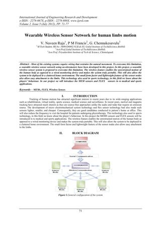
  • 1. International Journal of Engineering Research and Development e-ISSN : 2278-067X, p-ISSN : 2278-800X, www.ijerd.com Volume 2, Issue 5 (July 2012), PP. 71-77 Wearable Wireless Sensor Network for human limbs motion V. Naveen Raja1, P M Francis2, G. Chennakesavulu3 1 M.Tech Student, Rll.No: 10H91D6802,VLSI & ES, Gokul Institute of Tech&Science,Bobbili 2 Asst.Prof,Gokul Institute of Tech&Science,Bobbili. 3 Asst.Prof, Priyadarshini Institute of Tech & Science, Chintalapudi. Abstract—Most of the existing systems require wiring that restrains the natural movement. To overcome this limitation, a wearable wireless sensor network using accelerometers have been developed in this project. In this project, a wearable wireless sensor system is proposed to overcome this limitation. The wireless feature enables the unrestrained motion of the human body as opposed to a wired monitoring device and makes the system truly portable. This will also allow the system to be deployed in a cluttered home environment. The small form factor and lightweight feature of the sensor nodes also allow easy attachment to the limbs. This technology also used in sports technology, in this field we know about the players’ behaviour. In our project we will introduce the MEM sensors and FLEX sensors in to medical and sports applications. Keywords— MEMs, FLEX, Wireless Sensor. I. INTRODUCTION Tracking of human motion has attracted significant interest in recent years due to its wide-ranging applications such as rehabilitation, virtual reality, sports science, medical science and surveillance. In recent years, inertial and magnetic tracking have attracted much interest as they are source-free approaches unlike the audio and radar that require an emission source. The development of micro electromechanical system technology and flex sensor technology had also made such sensors lighter, smaller, and cheaper. Consequently, they are good candidates conducted in patient’s home or office. This will also reduce the frequency to visit the hospital for patients undergoing physiotherapy. This technology also used in sports technology, in this field we know about the player’s behaviour. In this project the MEMS sensors and FLEX sensors will be introduced in to medical and sports applications. The wireless feature enables the unrestrained motion of the human body as opposed to a wired monitoring device and makes the system truly portable. This will also allow the system to be deployed in a cluttered home environment. The small form factor and lightweight feature of the sensor nodes also allow easy attachment to the limbs. II. BLOCK DIAGRAM Figure 1.General configuration of the system 71
  • 2. Wearable Wireless Sensor Network for human limbs motion III. SERIAL COMMUNICATION Serial communication is basically the transmission or reception of data one bit at a time. Today's computers generally address data in bytes or some multiple thereof. A byte contains 8 bits. A bit is basically either a logical 1 or zero. Every character on this page is actually expressed internally as one byte. The serial port is used to convert each byte to a stream of ones and zeroes as well as to convert a stream of ones and zeroes to bytes. The serial port contains an electronic chip called a Universal Asynchronous Receiver/Transmitter (UART) that actually does the conversion. The serial port has many pins. We will discuss the transmit and receive pins first. Electrically speaking, whenever the serial port sends a logical one (1) a negative voltage is effected on the transmit pin. Whenever the serial port sends a logical zero (0) a positive voltage is affected. When no data is being sent, the serial port's transmit pin's voltage is negative (1) and is said to be in a MARK state. Note that the serial port can also be forced to keep the transmit pin at a positive voltage (0) and is said to be the SPACE or BREAK state. (The terms MARK and SPACE are also used to simply denote a negative voltage (1) or a positive voltage (0) at the transmit pin respectively).When transmitting a byte, the UART (serial port) first sends a START BIT which is a positive voltage (0), followed by the data (general 8 bits, but could be 5, 6, 7, or 8 bits) followed by one or two STOP Bits which is a negative(1) voltage. The sequence is repeated for each byte sent. When transmitting a character there are other characteristics other than the baud rate that must be known or that must be setup. These characteristics define the entire interpretation of the data stream. The first characteristic is the length of the byte that will be transmitted. This length in general can be anywhere from 5 to 8 bits. The second characteristic is parity. The parity characteristic can be even, odd, mark, space, or none. If even parity, then the last data bit transmitted will be a logical 1 if the data transmitted had an even amount of 0 bits. If odd parity, t hen the last data bit transmitted will be a logical 1 if the data transmitted had an odd amount of 0 bits. If MARK parity, then the last transmitted data bit will always be a logical 1. If SPACE parity, then the last transmitted data bit will always be a logical 0. If no parity then there is no parity bit transmitted. The third characteristic is the amount of stop bits. This value in general is 1 or 2. Assume we want to send the letter 'A' over the serial port. The binary representation of the letter 'A' is 01000001. Remembering that bits are transmitted from least significant bit (LSB) to most significant bit (MSB), the bit stream transmitted would be as follows for the line characteristics 8 bits, no parity, 1 stop bit and 9600 baud. LSB (0 1 0 0 0 0 0 1 0 1) MSB. The above represents (Start Bit) (Data Bits) (Stop Bit). To calculate the actual byte transfer rate simply divide the baud rate by the number of bits that must be transferred for each byte of data. In the case of the above example, each character requires 10 bits to be transmitted for each character. As such, at 9600 baud, up to 960 bytes can be transferred in one second. The above discussion was concerned with the "electrical/logical" characteristics of the data stream. We will expand the discussion to line protocol. Serial communication can be half duplex or full duplex. Full duplex communication means that a device can receive and transmit data at the same time. Half duplex means that the device cannot send and receive at the same time. It can do them both, but not at the same time. Half duplex communication is all but out-dated except for a very small focused set of applications. Half duplex serial communication needs at a minimum two wires, signal ground and the data line. Full duplex serial communication needs at a minimum three wires, signal ground, transmit data line, and receive data line. These signals are the Carrier Detect Signal (CD), asserted by modems to signal a successful connection to another modem, Ring Indicator (RI), asserted by modems to signal the phone ringing, Data Set Ready (DSR), asserted by modems to show their presence, Clear To Send (CTS), asserted by modems if they can receive data, Data Terminal Ready (DTR), asserted by terminals to show their presence, Request To Send (RTS), asserted by terminals if they can receive data. The section RS232 Cabling describes these signals and how they are connected. The above paragraph alluded to hardware flow control. Hardware flow control is a method that two connected devices use to tell each other electronically when to send or when not to send data. A modem in general drops (logical 0) its CTS line when it can no longer receive characters. Note that hardware flow control requires the use of additional wires. The benefit to this however is crisp and reliable flow control. Another method of flow control used is known as software flow control. This method requires a simple 3 wire serial communication link, transmit data, receive data, and signal ground. If using this method, when a device can no longer receive, it will transmit a character that the two devices agreed on. This character is known as the XOFF character. This character is generally a hexadecimal 13. When a device can receive again it transmits an XON character that both devices agreed to. This character is generally a hexadecimal 11. IV. FLEX SENSOR The Flex Sensor patented technology is based on resistive carbon elements. As a variable printed resistor, the Flex Sensor achieves great form-factor on a thin flexible substrate. When the substrate is bent, the sensor produces a resistance output correlated to the bend radius—the smaller the radius, the higher the resistance value. Flex sensors are sensors that change in resistance depending on the amount of bend on the sensor. They convert the change in bend to electrical resistance - the more the bend, the more the resistance value. They are usually in the form of a thin strip from 1"-5" long that vary in resistance from approximately 10 to 50 kilo ohms. They are often used in gloves to sense finger movement. 2.1. Attributes of FLEX Sensors  Custom designed to match customer specs  High level of reliability, consistency, repeatability  Harsh temperature resistance  Variety of flexible or stationary surfaces for mounting  Infinite number of resistance possibilities and bend ratios 72
  • 3. Wearable Wireless Sensor Network for human limbs motion 2.2. TILT ANGLE MEASUREMENT The movement of the human arm along sagittal plane, i.e., the plane that bisects the human body into left and right is investigated. This corresponds to the flexion and extension movements of the forearm and the upper arm. Flexion is a bending movement in which the relative angle of the joint between the adjacent segments decreases. Extension is a straightening movement in which the relative angle of the joint between two adjacent segment increases as the joint returns to the reference anatomical position. For the physical therapist, the range of the elbow motion and shoulder joint of the patient is of particular interest for monitoring the rehabilitation progress. To capture the arm’s rotational motion, an accelerometer is integrated to the sensor node as an inclinometer. Fig: 3. Tilt Angle Measurement in Y-Z Plane V. TILT/STATIC MEASUREMENT Figure 2 shows an accelerometer mounted on the forearm. In the static conditions, i.e., the arm is not moving; the tilt angle θ of the accelerometer can be determined by measuring the acceleration due to gravity g. The accelerations AY in the Y -axis and AZ in the Z-axis that are due to gravity can be determined as AY =g sin θ --------------(1) AZ =g cos θ.------------- (2) From (1) and (2), the tilt angle θ can be determined as θ = tan−1 AY/AZ ------------ . (3) The quadrant of θ can be determined by the sign of AY .The output voltage Vout of the accelerometer is related to the acceleration Ai of a particular axis (i = Y or Z) by the following relationship: Vout = Voffset + S × Ai ------------------(4) Where S = ΔV/Δg is the sensitivity of the accelerometer (in volts per meter per second squared), and Voffset is the offset of the accelerometer at 0g. The corresponding ADC value can be expressed as ---- (5) Where n is the resolution bits of the ADC (n = 8 in this case), V + REF and V−REF are the reference voltage levels, and Q[ ] is the quantized function. The accelerometer is ratio metric, i.e., the output voltage and sensitivity linearly scale with the reference voltage. From (4) and (5), it is observed that the supply induced errors are cancelled in the analog-to-digital conversion process. Substituting Vout from (4) into (5), the acceleration Ai is approximately proportional to λi after subtracting an equivalent ADC offset. As such, (3) can be rewritten as follows: θ = tan−1[ λY − λY o/ λZ – λZo] --------------(6) Where λY and λZ are the ADC output values of the accelerometer in the Y - and Z-axes, respectively, and λY o and λZo are the offsets of the accelerometer at 0g. 73
  • 4. Wearable Wireless Sensor Network for human limbs motion VI. MICROCHIP MPLAB IDE MPLAB Integrated Development Environment (IDE) is a free, integrated toolset for the development of embedded applications employing Microchip's PIC® and dsPIC® microcontrollers. MPLAB IDE runs as a 32-bit application on MS Windows®, is easy to use and includes a host of free software components for fast application development and super- charged debugging. MPLAB IDE also serves as a single, unified graphical user interface for additional Microchip and third party software and hardware development tools. Moving between tools is a snap, and upgrading from the free software simulator to hardware debug and programming tools is done in a flash because MPLAB IDE has the same user interface for all tools. The MPLAB IDE software brings an ease of software development previously unseen in the 8/16-bit microcontroller market. The MPLAB IDE is a Windows® based application that contains:  An interface to debugging tools  simulator  programmer (sold separately)  emulator (sold separately)  in-circuit debugger (sold separately)  A full-featured editor with colour coded context  A multiple project manager  Customizable data windows with direct edit of contents  High level source code debugging The MPLAB IDE allows you to:  Edit your source files (either assembly or C)  One touch assemble (or compile) and download to PIC micro emulator and simulator tools  Debug using:  source files (assembly or C)  absolute listing file (mixed assembly and C)  machine code MPLAB IDE supports multiple debugging tools in a single development paradigm, from the cost effective simulators, through low cost in-circuit debuggers, to full-featured emulators. This eliminates the learning curve when upgrading to tools with increasing flexibility and power. VII. EXPERIMENTAL RESULTS Figure 4 shows the experimental set up of the project. The transmitter and the receiver sections are connected to PC. The MEMS sensor and the FLEX sensor are connected to the transmitter, transmits the sensed data. Receiver is connected to the COM port of the computer. It receives the data and sends to the PC via RS232 cable. 74
  • 5. Wearable Wireless Sensor Network for human limbs motion Figure 4: Experimental Set up The MEMS sensor shown in figure 6.2 is attached to the forearm of the human as shown in figure 6.3. The FLEX sensor is attached to the fingers of the human as shown in figure 6.4. These sensors senses the movements of forearm and the fingers of the human and corresponding analog values are send to the microcontroller. Figure 4.1: MEMS Sensor Figure 4.3: MEMS Sensor attached to the human 75
  • 6. Wearable Wireless Sensor Network for human limbs motion The on chip ADC of the PIC microcontroller converts the analog value to Digital and sends to the RF transceiver which is then transmitted to the receiver. The receiver receives the data and sends it to the microcontroller which is then serially transmitted to the PC. The data is displayed on the PC with the help of hyper terminal. Figure 4.2 : FLEX sensor attached to the finger of human As the movements of forearm and fingers of human changes, the corresponding values are displayed on the PC as shown in the figure 6.5. Figure 4.4: Results displayed on PC VIII. FUTURE SCOPE An ambulatory and unrestrained measurement system based on a wearable wireless sensor network for tracking the human arm motion in the sagittal plane has been proposed. The wireless feature enables the unrestrained motion of the human body as opposed to a wired monitoring device and makes the system truly portable. This allows the system to be 76
  • 7. Wearable Wireless Sensor Network for human limbs motion deployed in a cluttered home environment. The small form factor and lightweight feature of the sensor nodes also allow easy attachment to the limbs. As compared with other existing approaches, the new system is portable and easy to use. It allows the patients to be monitored without restraint, and rehabilitation can be carried out in a home environment instead of a specialized laboratory in the hospital. For future work, experiments conducted with stroke patients in collaboration with a hospital are being planned using the developed system. More tests can also be conducted to investigate the effect of RF interference from other patient monitoring devices and wireless systems. REFERENCES [1]. H. Zhou and H. Hu, ―Human motion tracking for rehabilitation—A survey,‖ Biomed. Signal Process. Control, vol. 3, no. 1, pp. 1–18, Jan. 2008. [2]. J.M. Zheng, K.W. Chan, and I. Gibson, ―Virtual reality,‖ IEEE Potentials, vol. 17, no. 2, pp. 20–23, Apr. 1998. [3]. D. Jack, R. Boian, A. S. Merians, M. Tremaine, G. C. Burdea, S. V. Adamovich, M. Recce, and H. Poizner, ―Virtual reality - enhanced stroke rehabilitation,‖ IEEE Trans. Neural Syst. Rehabil. Eng., vol. 9, no. 3, pp. 308–318, Sep. 2001. [4]. D. Fitzgerald, J. Foody, D. Kelly, T. Ward, C. Markham, J. McDonald, and B. Caulfield, ―Development of a wearable motion capture suit and virtual reality biofeedback system for the instruction and analysis of sports rehabilitation exercises,‖ in Proc. 29th Annu. Int. Conf. IEEE EMBS, 2007, pp. 4870–4874. [5]. T. B.Moeslund, A. Hilton, and V. Krüger, ―A survey of advances in visionbased human motion capture and analysis,‖ Comput. Vis. Image Underst. 77