Contenu connexe
Similaire à IGRP and EIGRP
Similaire à IGRP and EIGRP (20)
IGRP and EIGRP
- 1. Institute of Computer Technology - Vienna University of Technology Institute of Computer Technology - Vienna University of Technology
L43 - IRGP and EIGRP L43 - IRGP and EIGRP
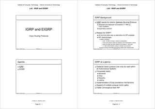
IGRP Background
IGRP stands for Interior Gateway Routing Protocol
designed and deployed successfully in 1986 by
Cisco Systems
proprietary protocol
IGRP and EIGRP
Reason for IGRP?
At this time there was no alternative for RIP available
Cisco Routing Protocols
RIP disadvantages:
Metric limitation
max. 15 hops (16 hops = network unreachable)
Hop count doesn't reflect the capacity of the transmission medias
takes the least hop path instead of the fastest or „best path“
=> didn't allow flexible routing in complex environments
much routing overhead (full routing table every 30seconds)
© 2005, D.I. Manfred Lindner IGRP-EIGRP, v3.5 1 © 2005, D.I. Manfred Lindner IGRP-EIGRP, v3.5 3
Agenda IGRP at a glance
IGRP Distance vector protocol (can only be used within
EIGRP an Autonomous System)
Composite metric
Bandwidth
Delay
Reliability
Loading
Implementation of loop avoidance mechanisms
Support of multiple unequal-metric paths
Faster convergence than RIP
© 2005, D.I. Manfred Lindner IGRP-EIGRP, v3.5 2 © 2005, D.I. Manfred Lindner IGRP-EIGRP, v3.5 4
© 2005, D.I. Manfred Lindner © 2005, D.I. Manfred Lindner
Page 43 - 1 Page 43 - 2
- 2. Institute of Computer Technology - Vienna University of Technology Institute of Computer Technology - Vienna University of Technology
L43 - IRGP and EIGRP L43 - IRGP and EIGRP
IGRP / EIGRP Metric calculation IGRP / EIGRP Metric calculation
Bandwidth Delay
unit: bits/sec unit: 10 microseconds
it is the sum of the transmission delays along the path
default values for LANs
and is stored in a 32-bit field, in increments of 39.1
corresponding to real bandwidth
nanoseconds
default values for serial lines all 1´s indicates an unreachable destination
corresponding to bandwidth of 1.544Mbps (T1 line)
default values for LANs
configuration of the real bandwidth on serial lines is a must!!!
corresponding to real delay
cisco interface command: bandwidth <number in kbit/s>
default values for serial lines
minimum bandwidth along a path is taken
corresponding to delay of 1.544Mbps (T1 line)
BWIGRP is expressed by (1/bandwidth)*1017 configuration of the real delay on serial lines is an option
BWEIGRP is expressed by (1/bandwidth)*1017*256 cisco interface command: delay <number in tens of usec>
DelayIGRP is expressed by (delay/10)
The range is from a 1200bps line to 10 terabits per
DelayEIGRP is expressed by (delay/10)*256
second
© 2005, D.I. Manfred Lindner IGRP-EIGRP, v3.5 5 © 2005, D.I. Manfred Lindner IGRP-EIGRP, v3.5 7
IGRP / EIGRP Metric calculation IGRP / EIGRP Metric calculation
Bandwidth Delay
metric values for bandwidth as part of composite metric: metric values for delay as part of composite metric:
assumption: bandwidth for serial links is configured properly assumption: delay for serial links is default value for T1
otherwise all serial links will have metric of T1
Delay DelayEIGRP DelayIGRP
Bandwidth BWEIGRP BWIGRP Satellite (2 sec) 51.200.000 200.000
Satellite (500 Mbit/s) 5.120 20 100 Mbit Ethernet (0,1 ms) 25.60 10
Ethernet (100 Mbit/s) 256.000 100 10 Mbit Ethernet (1 ms) 25.600 100
Ethernet (10 Mbit/s) 256.000 1.000 Token Ring 4 ( 2,5ms) 64.000 250
Token Ring (4 Mbit/s) 640.000 2.500 Token Ring 16 ( 0,6ms) 16.000 62,5
Token Ring (16 Mbit/s) 160.000 625 FDDI 100 ( 0,1ms) 2.560 10
FDDI (100 Mbit/s) 256.000 100 serial links:
1.544 Mbps 1.657.856 6.476 1.544 Mbps (20 ms) 512.000 2.000
128 kbps 20.000.000 78.125 128 kbps (20 ms) 512.000 2.000
64 kbps 40.000.000 156.250 64 kbps (20 ms) 512.000 2.000
56 kbps 45.714.176 178.571 56 kbps (20 ms) 512.000 2.000
10 kbps 256.000.000 1.000.000 10 kbps (20 ms) 512.000 2.000
1 kbps 2.560.000.000 10.000.000 1 kbps (20 ms) 512.000 2.000
© 2005, D.I. Manfred Lindner IGRP-EIGRP, v3.5 6 © 2005, D.I. Manfred Lindner IGRP-EIGRP, v3.5 8
© 2005, D.I. Manfred Lindner © 2005, D.I. Manfred Lindner
Page 43 - 3 Page 43 - 4
- 3. Institute of Computer Technology - Vienna University of Technology Institute of Computer Technology - Vienna University of Technology
L43 - IRGP and EIGRP L43 - IRGP and EIGRP
IGRP Metric calculation IGRP Metric calculation
Reliability Formula for metric calculation
arbitrary number defaults:
k1=1, k2=0, k3=1, k4=0, k5=0
255 means 100%
K1 til K5 are arbitrary numbers which can be configured
1 means 0%
worst reliability between source and destination k 2 ∗ min BWIGRP
metric1 = k1 ∗ min BWIGRP + + k 3 ∗ sumDelay IGRP
dynamically measured 256 - load
keepalives are sent off the interface every 10 seconds, frame has
CRC
If k5 doesn´t equal 0, an additional operation is done
doesn´
k5
samples are calculated over 5 minutes compositem etric = metric1 ∗
time interval needs reconfiguration, when Reliability is reliabilit y + k 4
used
For default values of k parameters:
compositem etric = k1 ∗ min BWIGRP + k 3 ∗ sumDelay IGRP
© 2005, D.I. Manfred Lindner IGRP-EIGRP, v3.5 9 © 2005, D.I. Manfred Lindner IGRP-EIGRP, v3.5 11
IGRP Metric calculation IGRP Metric example 1
Loading
arbitrary number Prefered Path!!!
Load is given as a fraction of 255. A load of 255 indicates a Metric=BW+delay=78125+2000=80125
Metric=BW+delay=78125+2000=80125
completely saturated link
dynamically measured 128kbps
calculated over 5 minutes
128kbps 64kbps
time interval needs reconfiguration, when Loading is used
Metric=min.BW along the path+sum of delays =156250+2000+2000=160250
Metric=min.BW =156250+2000+2000=160250
© 2005, D.I. Manfred Lindner IGRP-EIGRP, v3.5 10 © 2005, D.I. Manfred Lindner IGRP-EIGRP, v3.5 12
© 2005, D.I. Manfred Lindner © 2005, D.I. Manfred Lindner
Page 43 - 5 Page 43 - 6
- 4. Institute of Computer Technology - Vienna University of Technology Institute of Computer Technology - Vienna University of Technology
L43 - IRGP and EIGRP L43 - IRGP and EIGRP
IGRP Metric example 2 IGRP multiple paths
Configured variance=2
Metric=BW+delay=78125+2000=80125
Metric=BW+delay=78125+2000=80125
Metric=BW+delay=78125+2000=80125
Metric=BW+delay=78125+2000=80125 IP IP
IP
IP IP
128kbps IP 128kbps IP
1,544Mbps 1,544Mbps IP
IP
IP
128kbps 64kbps
Pr !!!
efe th
re Pa
dP e d
ath er
ef
!!! Pr
Metric=min.BW along the path+sum of delays =6476+2000+2000=10476
Metric=min.BW =6476+2000+2000=10476 Metric=min.BW along the path+sum of delays =156250+2000+2000=160250
Metric=min.BW =156250+2000+2000=160250
© 2005, D.I. Manfred Lindner IGRP-EIGRP, v3.5 13 © 2005, D.I. Manfred Lindner IGRP-EIGRP, v3.5 15
IGRP multiple paths IGRP Metric
Support of up to 6 parallel paths (default:4) to the Routing updates also include a count of hops and a
destination for load balancing computation of the path MTU
default: same metric for parallel paths is necessary => max. network diameter 255 hops (IP TTL-field)
default: 100 hops
Support of unequal-metric load balancing
Prerequisite: configuration of a variance factor
The alternative path metric must be within the specified
variance of the best local metric
© 2005, D.I. Manfred Lindner IGRP-EIGRP, v3.5 14 © 2005, D.I. Manfred Lindner IGRP-EIGRP, v3.5 16
© 2005, D.I. Manfred Lindner © 2005, D.I. Manfred Lindner
Page 43 - 7 Page 43 - 8
- 5. Institute of Computer Technology - Vienna University of Technology Institute of Computer Technology - Vienna University of Technology
L43 - IRGP and EIGRP L43 - IRGP and EIGRP
IGRP & default routes IGRP Loop avoidance & timers
RIP and OSPF are using 0.0.0.0 as their default Routing update timer: 90 seconds
route (=>metric is not related to a distance)
IGRP allows to mark real networks as „candidates Hold-down timer: (3*90sec)+10sec=280sec
for being default“
e.g. if multiple exit points to the Internet exist, then this Invalid timer: 3*90sec=270sec
implementation allows to choose the optimal „border (starts in the absence of routing information about a
router“ specific route)
candidate for being default
194.96.4.4/30 Flush timer: 7*90sec=630sec
IGRP Internet How much time should pass before a route should be
194.96.4.8/30
flushed from the routing table
candidate for being default
© 2005, D.I. Manfred Lindner IGRP-EIGRP, v3.5 17 © 2005, D.I. Manfred Lindner IGRP-EIGRP, v3.5 19
IGRP Loop avoidance & timers IGRP Protocol stack
Periodical Routing updates OSI stack
destination address: 255.255.255.255
Topology changes are reported with triggered
updates
Hold-downs
Split horizon IGRP
9 IP protocol number 9 (decimal)
Route Poisoning Updates IP
are intended to defeat larger routing loops
Data link layer
are sent if a route metric has increased by a factor of 1.1
or greater Physical layer
© 2005, D.I. Manfred Lindner IGRP-EIGRP, v3.5 18 © 2005, D.I. Manfred Lindner IGRP-EIGRP, v3.5 20
© 2005, D.I. Manfred Lindner © 2005, D.I. Manfred Lindner
Page 43 - 9 Page 43 - 10
- 6. Institute of Computer Technology - Vienna University of Technology Institute of Computer Technology - Vienna University of Technology
L43 - IRGP and EIGRP L43 - IRGP and EIGRP
Agenda EIGRP at a glance
IGRP Advanced distance vector protocol (can only be
EIGRP used within an AS)
uses exactly the same metric as IGRP
Loop avoidance by DUAL
DUAL: Diffusing Update Algorithm
evolved by Mr. J.J. Garcia-Luna-Aceves
Event triggered updates (Multicasts)
Fast convergence
© 2005, D.I. Manfred Lindner IGRP-EIGRP, v3.5 21 © 2005, D.I. Manfred Lindner IGRP-EIGRP, v3.5 23
EIGRP Background EIGRP at a glance
EIGRP stands for Enhanced Interior Gateway Routing Support of multiple unequal-metric paths
Protocol
Classless routing protocol (supports route
proprietary protocol
tries to combine the advantages of the distance vector and the link summarization)
state protocol world without their specific problems Update contains network plus prefix
Distance vector
advantages:
It supports IP, IPX and Appletalk
less CPU power and memory usage, simple configuration
disadvantages:
slow convergence, lot of routing overhead, possibility of loops
Link state
advantages:
fast convergence, no loops, better metric (cost factor)
disadvantages:
high CPU power and memory usage (SPF algorithm, LS database), not so
easy to configure (area concept)
© 2005, D.I. Manfred Lindner IGRP-EIGRP, v3.5 22 © 2005, D.I. Manfred Lindner IGRP-EIGRP, v3.5 24
© 2005, D.I. Manfred Lindner © 2005, D.I. Manfred Lindner
Page 43 - 11 Page 43 - 12
- 7. Institute of Computer Technology - Vienna University of Technology Institute of Computer Technology - Vienna University of Technology
L43 - IRGP and EIGRP L43 - IRGP and EIGRP
EIGRP Concepts EIGRP Concepts
R2 R8
Hello Hello Hello
1st : Every EIGRP router has to discover its Hello N
e
neighbors t
w
Hello
R3 R5 R6 o
it´s done with a Hello protocol Hello Hello Hello Hello r
R1
Hello k
a Router doesn´t expect an acknowledge for its Hello
Hello Hello
X
network type dependent
Token
Point-to-point network R4 R7 Ring
Hello Hello Hello
Multiaccess with broadcast/multicast support (BMA) FDDI
Hello
NBMAs nonbroadcast multiaccess network
2nd: based on this Hellos it builds a neighbor table
Neighbor table R1 Neighbor table R2 Neighbor table R3 Neighbor table R4
When a newly discovered neighbor is learned, the
R2 R1 R1 R1
address and interface of the neighbor is recorded.
R3 R3 R2 R2
The HoldTime is the amount of time a router treats a R4 R4 R4 R3
neighbor as reachable and operational: 3* Hello interval R8 R5 R7
© 2005, D.I. Manfred Lindner IGRP-EIGRP, v3.5 25 © 2005, D.I. Manfred Lindner IGRP-EIGRP, v3.5 27
EIGRP Concepts EIGRP Concepts
Point-to-Point: Neighbor relationship is formed
Point- to- Point:
with the router on the other end
3rd:After the neighbor discovery a Topology table is
Hello time interval: 5 sec built
Neighbor routers exchanging their complete routing
tables and store these informations in a Topology table
Broadcast multiaccess: Neighbor relationships
multiaccess: information exchange through Update packets
are formed dynamically using multicast hellos
Hello time interval: 5 sec Update packets
Multicast address: 224.0.0.10
contain a sequence number field in the header and must be
acknowledged by the receiver (reliable transmission)
are sent in the following instances:
when a neighbor first comes up (packet´s dest. addr is an unicast)
when a network has failed (packet´s dest. addr. is 224.0.0.10)
F/R
Nonbroadcast multiaccess: Neighbor relationships
multiaccess: X.25
when there is a metric change for a certain destination (packet´s
are formed by manual configuration ATM dest. addr. is 224.0.0.10)
Hello time interval: 60sec
Dest. Address: Unicast address of the
neighbor
© 2005, D.I. Manfred Lindner IGRP-EIGRP, v3.5 26 © 2005, D.I. Manfred Lindner IGRP-EIGRP, v3.5 28
© 2005, D.I. Manfred Lindner © 2005, D.I. Manfred Lindner
Page 43 - 13 Page 43 - 14
- 8. Institute of Computer Technology - Vienna University of Technology Institute of Computer Technology - Vienna University of Technology
L43 - IRGP and EIGRP L43 - IRGP and EIGRP
EIGRP Concepts EIGRP Concepts
Update packets Topology Table
In contrast to OSPF every EIGRP router is modifying any Stores routing information that neighbors exchange after
received update packet. It adds its own local distance to the first Hello exchange (=> smaller compared to an
the information and sends the packet with an own OSPF topology table). DUAL acts on the Topology table
sequence number to its neighbors. to determine Successors and FSs.
Successor:
A neighbor that has been selected as the next hop for a destination,
it ends up in the Routing Table
Feasible Successor (FS):
A neighbor that has satisfied the Feasibility Condition and has a path
to the destination (is an alternate route to the current successor)
Feasibility Condition (FC):
A condition that is met when the lowest of all the neighbors' costs
plus the link cost to that neighbor is found, and the neighbor's
advertised cost is less than the current successor's cost.
© 2005, D.I. Manfred Lindner IGRP-EIGRP, v3.5 29 © 2005, D.I. Manfred Lindner IGRP-EIGRP, v3.5 31
EIGRP Concepts EIGRP Topology table and feasible successor
R2 R8
R2 NetY ad:20 R8 Net X ad:26 16 N
Ack. Update 16 Ack. N e
e t
10 NetY t w
ad:40 w R3 R5 R6 10 o
NetY ad:20 NetY ad:120 Update
R3 R5 R6 NetY ad:220 o 10 Net X ad:216 r
Update Update R1 100 100
NetY ad:10 Ack. Update r k
R1 Update 100 100 k
10 X
Ack. Ack.
X
Token 6
R4 1 R7
Token 6 Ring
R4 NetY ad:20 1 R7 Net X ad:17
10 Ring
Ack. Update FDDI
New network Y FDDI
Ack. Update
NetY ad:21
Part of R1´s Topology Table
R1´
Network Advertised Distance Feasible Distance Neighbor
Update propagation Successor X 17 27 R4
ad = advertised distance X 216 226 R3
Feasible Successor X 26 36 R2
© 2005, D.I. Manfred Lindner IGRP-EIGRP, v3.5 30 © 2005, D.I. Manfred Lindner ad = advertised distance
IGRP-EIGRP, v3.5 32
© 2005, D.I. Manfred Lindner © 2005, D.I. Manfred Lindner
Page 43 - 15 Page 43 - 16
- 9. Institute of Computer Technology - Vienna University of Technology Institute of Computer Technology - Vienna University of Technology
L43 - IRGP and EIGRP L43 - IRGP and EIGRP
EIGRP Topology table without EIGRP Active state
feasible successor
R2 R8
Net X ad:36 26 N Active state
e
t A router's state for a destination when it has lost its successor to
w that destination and has no other feasible successor (FS)
R3 R5 R6 10 o
10 Net X ad:216 100 r available. The router is forced to compute a route to the
R1 100
k destination.
X It´s sending a query packet to all its neighbors.
Token 6 Query packet (will be acknowledged from the receiver)
R4 1 R7
Net X ad:17
Ring Sent to all neighbors when a router goes into Active for a destination
FDDI and is asking for information on that destination. Unless it receives
replies back from all its neighbors, the router will remain in Active
state and not start the computation for a new successor.
Part of R1´s Topology Table
R1´ Reply packet (will be acknowledged from the receiver)
Sent by every EIGRP neighbor which receives a query. If the
Network Advertised Distance Feasible Distance Neighbor
neighbor doesn't have the information, it queries its neighbors
Successor X 17 27 R4 indicating that it is also performing route recomputation
X 216 226 R3
no Feasible
Successor!!! X 36 46 R2
© 2005, D.I. Manfred Lindner ad = advertised distance
IGRP-EIGRP, v3.5 33 © 2005, D.I. Manfred Lindner IGRP-EIGRP, v3.5 35
EIGRP Active state EIGRP Topology table
without feasible successor
R2 R8
Reply 9
If the successor disappears from the topology table 26 N
e
because of a network change and there is a Ack 1 t
w
Active State
feasible successor, DUAL keeps the route in a R1 Reply 17
R3 R5 R6 10 o
r
Query 1 100 100
passive state. k
Ack 1
X
Passive state Ack 9
Ack 17 Token 6
A router's state after losing its successor when it has an FS to the R4 1 R7 Ring
destination available in its Topology table
10 FDDI
If the successor disappears from the topology table
because of a network change and there is no Part of R1´s Topology Table
R1´
feasible successor, DUAL puts the route into the
Network Advertised Distance Feasible Distance Neighbor
active state. Successor X 17 27 R4
X 216 226 R3
no Feasible
Successor!!! X 36 46 R2
© 2005, D.I. Manfred Lindner IGRP-EIGRP, v3.5 34 © 2005, D.I. Manfred Lindner IGRP-EIGRP, v3.5 36
© 2005, D.I. Manfred Lindner © 2005, D.I. Manfred Lindner
Page 43 - 17 Page 43 - 18
- 10. Institute of Computer Technology - Vienna University of Technology Institute of Computer Technology - Vienna University of Technology
L43 - IRGP and EIGRP L43 - IRGP and EIGRP
EIGRP Topology table EIGRP Compatibility
without feasible successor
R2 R8
Ack automatic redistribution
26 N
e
t IGRP
EIGRP AS100
w
AS100
R3 R5 R6 10 o
R1 Ack r
Update 100 100
k
X manual redistribution
Passive State Token 6
R4 1 R7 Ring EIGRP
IGRP
10 AS 397
FDDI AS100
Part of R1´s Topology Table
R1´
manual redistribution
Network Advertised Distance Feasible Distance Neighbor
all other IP
EIGRP routing
AS100 protocols
X 216 226 R3
Successor X 36 46 R2
© 2005, D.I. Manfred Lindner IGRP-EIGRP, v3.5 37 © 2005, D.I. Manfred Lindner IGRP-EIGRP, v3.5 39
EIGRP Compatibility EIGRP Protocol stack
Route tagging OSI stack
EIGRP has the notion of internal and external routes.
Internal routes
are ones that have been originated within an EIGRP autonomous
system (AS).
External routes
are ones that have been learned by another routing protocol or
reside in the routing table as static routes. EIGRP
88 IP protocol number 88 (decimal)
Route redistribution IP
in the case of IGRP is done automatically, when EIGRP
Data link layer
and IGRP are belonging to the same Autonomous
System (compatible metric!!!). IGRP derived routes are Physical layer
treated as external routes in EIGRP (also OSPF, RIP,
EGP, BGP...)
© 2005, D.I. Manfred Lindner IGRP-EIGRP, v3.5 38 © 2005, D.I. Manfred Lindner IGRP-EIGRP, v3.5 40
© 2005, D.I. Manfred Lindner © 2005, D.I. Manfred Lindner
Page 43 - 19 Page 43 - 20