Cone Ring Traction Drive
•
0 j'aime•60 vues

https://irjet.net/archives/V5/i1/IRJET-V5I1276.pdf

Recommandé
Recommandé
Contenu connexe
Tendances
Tendances (20)
Similaire à Cone Ring Traction Drive
Similaire à Cone Ring Traction Drive (20)
Plus de IRJET Journal
Plus de IRJET Journal (20)
Dernier
Dernier (20)
Cone Ring Traction Drive
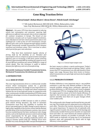
- 1. International Research Journal of Engineering and Technology (IRJET) e-ISSN: 2395-0056 Volume: 05 Issue: 01 | Jan-2018 www.irjet.net p-ISSN: 2395-0072 © 2018, IRJET | Impact Factor value: 6.171 | ISO 9001:2008 Certified Journal | Page 1293 Cone Ring Traction Drive Dhiraj Gunjal1, Rohan Khaire2, Kiran Deore3, Nilesh Gund4, B.S.Dange5 1,2,3,4 BE student Mechanical, SND COE & RC, YEOLA, Maharashtra, India 5 Asst. Prof. Mechanical, SND COE & RC, YEOLA, Maharashtra, India ---------------------------------------------------------------------***--------------------------------------------------------------------- Abstract – For years, CVTs have been targeted at reducing vehicle fuel consumption and emissions, requiring high efficiency an sufficient ratio spread. A fun to drive isimportant for customer acceptance in Europe. The breach of new transmission concepts such as 6-speed stepped involuntary, auto-shift physical and twin clutch transmissions places new challenges for a state of the art CVT transmission concept. Effective gear ratio can be changed through infinite numbers through continuously variable transmission (CVT) between maximum and minimum values. This is overcome on others which permit few gear ratio selections. They have been maintained angular velocity of driving shaft by the flexibility of cvt. Therefore fuel Consumption is less as compare to speed variation and engine efficiency goes on increasing. A belt drive system achieving efficiency approximately 88% by enabling the enginetorunat its most efficient revolutions per minute (RPM) for a range of vehicle speeds. Thus this technique is useful to balance between fuel efficiency and cost of manufacturing. Key words: Continuous Variable Transmission System, Mechanical Transmission, Revolutions per minute. 1.1INTRODUCTION 1.1.1. NEED OF STUDY The cone ring transmission drive is a continuously variable friction wheel transmission system for a generally performance spectrum. The design of cone ring traction is a purely mechanical base. It’s simple and robust components without the use of any hydraulic pump. In comparison with other continuously variable transmissions(CVTs)thiscauses significant advantages in terms of manufacturing costs and efficiency. Basic Characteristics of KRG Concept in order to achieve good vehicle driving dynamics, any kind of automatic transmission must have the capability to translate the driver’sgas pedal input. For KRG, change in quick requires a high torque capability of the friction contact andtheshortest possible delay of the involved dynamic systems. Any control function needed beyond the basic mechanical ratio change system, such as the hydraulic pressure control andveryhigh power requirements for the gear change actuator of conventional CVTs. Thus, avoiding a hydraulic system and using an actuator system with low “shifting” forces were decided very early during the KRG concept development as Fig.1.1.1. Conical input output cone the basic means to achieve a sporty performance. Today’s modern engine fuel island maps are getting “flatter”, which means that CVT transmissions can only take benefit of their larger ratio range. Because these force levels in friction- wheel transmissions are quite high and must also be applied constantly. 1.1.2. PROBLEM STATEMENT Problem definition is very important step in any problem resolution is said that well defined problem is half way towards problem solving hence systematic approach of problem definition. i.e. 4W 1H (4 why and 1 how) isadopted. To compensate CVTs for changing vehicle speeds, allowing the engine speed to remain at its level of peak efficiency. It improves fuel economy and exhaust emissions. As CVTs operate smoothly since there are no gear changes which cause sudden jerks. The continuously ratio change is performed bytwoconeand one ring. This transfer part are separated via an oil filmfrom each other. Therefore the traction characteristic of this oil has a great importance. To improve the oil optimally with regard to power transfer, the oil storage for the bearingsand continuously variable friction power transfer are separated from each other. As a start element all common systems in the automotive industry are possible in principle. As the CRTD needs no hydraulic oil pump due to its mechanical pressure units and automated dry clutch with its high efficiency is best qualified.
- 2. International Research Journal of Engineering and Technology (IRJET) e-ISSN: 2395-0056 Volume: 05 Issue: 01 | Jan-2018 www.irjet.net p-ISSN: 2395-0072 © 2018, IRJET | Impact Factor value: 6.171 | ISO 9001:2008 Certified Journal | Page 1294 1.2. OBJECTIVES To compensate CVTs for changing vehicle speeds. As CVTs operate smoothly since there are no gear changes which cause sudden jerks. The traction drivemechanism produces smooth rotation and eliminatesspeed irregularityduetothe high frequency vibration inherent in gear transmission . 1.3. BASIC CHARACTERISTICS OF CONE RING CVT (KRG) CONCEPT In order to achieve good vehicle driving dynamics, any kind of automatic transmission must have the capability to translate the driver’s gas pedal input for a dynamic acceleration into a quick change of transmission gear ratio, but at the same time smooth torque transition. For the KRG concept, quick ratio changesrequire a high torquecapability of the friction contact and the shortest possible delay of the involved dynamic systems. Any control function needed beyond the basic mechanical ratio change system, such as the hydraulic pressure control and very high power requirements for the gear change actuator of conventional CVTs, necessarily leads to unwanted delays in the shifting process. Thus avoiding a hydraulic system and using an actuator system with low “shifting” forcesweredecidedvery early during the KRG concept development as the basic means to achieve a sporty performance feeling. Today’smodern engine fuel island mapsaregetting“flatter”, which means that CVT transmissions can only takebenefitof their larger ratio range, if the associated improvementinthe engine operating point is not compensated by a low transmission efficiency, particularly at light loads. The demand for applying clamping forces to the power transmission elementshas a decisive influencehere,because these force levels in friction-wheel transmissions are quite high and must also be applied constantly. For automotive mass production, robust design and low manufacturing costs are imperative requirements. The design of the KRG variator system is kept very simple and insensitive to manufacturing tolerances. Cost estimations have shown a great potential compared toconventionalCVT concepts. 1.4 METHODOLOGY Types of CVT The types of CVT are as given below: 1.4.1 Variable-Diameter Pulley (VDP) or Reeves Drive: In the CVT system, two V-belt pulleys with V-belt running between them. The gear ratio is changed by moving the two sheaves of one pulley closer together and the two sheavesof the other pulley farther apart. Because of the crosssectionof V-shaped belt it is travel with higher speed on one pulley and lower speed on the another pulley. This changes the effective diameters of both pulleys, which changes the overall gear ratio. It is not possible to change the distance between the pulley and length of belt. Both pulleys are adjusted by maintain the tension on belt. 1.4.2 Toroidal or Roller-Based CVT: Toroidal CVTs are consist of discs and roller that transmit the power between the discsby meansof tractive force.The discs can be pictured as two almost conical parts, point to point, with the sidesdished such that the two parts could fill the central hole of a torus. One disc is the input, and the other is the output. A viscous fluid (EHL) is placed between the rollers and discs. The change in angle by a roller must be mirrored by the opposing roller. The position of the roller is controlled hydraulically .One disc connects to the engine. This is equivalent to the driving pulley. Anotherdisc connect to the drive shaft This is equivalent to the driven pulley. Rollers or wheels located between the disc act like the belt and transmitting power from one disc to the other. 1.4.3 Cone CVTs: Belong to this category all the all the CVTs that are constituted by one or more conical bodies that co-operate along their respective generatrices, thus realizing the variation. In the one cone type there is a revolving body (wheel) that, moving on the generatrix of the cone, creates the variation between the inferior and the superiordiameter of the cone. 1.4.4. Cone Ring Traction Drive: This is used in this project. Automatic transmissions with high performance and low production costs for low and middle class cars are hardly available on the current transmission market. With the Cone Ring traction Drive has a promising transmission under development thatoffersthe driver a multifunctional power train with various driving programs. • Continuously variable ratio change (CVT-Mode) • 60 Gear Automatic/manual Shifting The cone ring traction driveis not only for frontwheeldrive but also offers various options for rear wheel drive and for high torques. 1.5.PRINCIPLE AND WORKING OF CVT 1.5.1.Principle:- The ratio is continuously varying due to the two cones and one ring These transfer parts are in constant contact with each other. Thus traction drive has a huge importance. To
- 3. International Research Journal of Engineering and Technology (IRJET) e-ISSN: 2395-0056 Volume: 05 Issue: 01 | Jan-2018 www.irjet.net p-ISSN: 2395-0072 © 2018, IRJET | Impact Factor value: 6.171 | ISO 9001:2008 Certified Journal | Page 1295 improve the torque characteristics with regarding to power transfer the output cone can be displaced axially. The quick ratio change to the required ratio position is effected via little translation motions on the transfer ring by the adjusting speed changing knob. Due to immersion lubrication of variator and a simple mechanical pressure unit for generating, the clampingforce the cone needs no hydraulics. Therefore, a high efficiency and a low weight are achieved. 1.5.2 Working:- a) General : When motor is started, it just drives the input cone shaft via open belt drive. The input cone transmits the motion to the variator cone ring, which in turn drives output cone and thereby the output shaft. b) Speed Changing : The speed changing knob when turned rotates the speed changing screw, thereby effecting the translation of the nut and thereby that of the ring holder and the variator cone ring. The translation changes the constant ratio in between the two cones, thereby effecting speed change. The speed changes are continuous and can be made without stopping or disconnecting the drive. c) Torque Adjustment: The output cone can slide axially and the displacement is governed by KM3 locknut. The preload in the system is maintained by the helical compression spring and thethrust arrangement. The variator cone ring connects the two cones and hence when the output cone is axially displaced it changes the radial load and thereby the torque. Fig.1.5.2. Cone ring traction drive 1.6 ADVANTAGES AND APPLICATION 1.6.1. Advantages 1) Multiple speed can be obtained 2) Easy of operation; the speed changes are gradual,without any shock. 3) Singular control, entire range of speed is covered by a single hand wheel control. 4) Low cost 5) Compact size 6) Torque adjustment is possible 1.6.2. Applications 1) Agricultural equipment 2) Power tool and generators 3) Power take off applications 4) Wind energy 5) Automobile 6) Motorcycles 7) Watercraft 1.7. CONCLUSION CVTs is used for changing speed of vehicle, allow the engine speed to remain at its level of peak efficiency. It will improves fuel economy and exhaust emissions. CVTs operate smoothly since there are no gear changes which cause sudden jerks. Many small tractors for home and garden use have simple hydrostatic or rubber belt CVTs. For example, John Deere Gator line of small utility vehicles use a belt with a conical pulley system. They can deliver a lot of power and can reach speeds of 10-15 MPH, all without need for a clutch or shift gears. In general snowmobiles and motor scooters are use CVTs. almost all snowmobile and motor scooter CVTs are rubber belt/variable pulley CVTs. REFERENCES 1) Todd J. Furlong Judy M. Vance, Pierre M. Larochelle, “SPHERICAL MECHANISM SYNTHESIS IN VIRTUAL REALITY”, Proceedings of DETC98: Design Automation Conference September 13-16, 1998, Atlanta, Georgia. 2) I. A. Chironis, “Mechanisms and Mechanical Linkages.”
- 4. International Research Journal of Engineering and Technology (IRJET) e-ISSN: 2395-0056 Volume: 05 Issue: 01 | Jan-2018 www.irjet.net p-ISSN: 2395-0072 © 2018, IRJET | Impact Factor value: 6.171 | ISO 9001:2008 Certified Journal | Page 1296 3) H. Komatsubara, T. Yamazaki, S. Kuribayashi,”Research Development of Cone to Cone Type CVT”, 12th IFToMM World Congress, Besancon (France), June 18-21, 2007. 4) Shuzou Sanda, Kisaburo Hayakawa,” Traction Drive System and its Characteristics as Power Transmission”, Special Issue Basic Analysis Towards Further Development of Continuously Variable Transmissions, July 12, 2005. 5) Erdman and Sandor, “Engineering Mechanism”. 6) Konstantin Ivanov , “Self-Adjusting Motor-Wheel with CVT”, International Journal of Engineering and Innovative Technology (IJEIT) Volume 2, Issue 5, November 2012, ISSN: 2277-3754 ISO 9001:2008 Certified. BIOGRAPHIES: Dhiraj B. Gunjal, SND COE Yeola, Pune University, Department of Mechanical Engineering. Rohan B. Khaire, SND COE Yeola, Pune University, Department of Mechanical Engineering. Kiran R. Deore, SND COE Yeola, Pune University, Department of Mechanical Engineering. Nilesh G. Gund, SND COE Yeola, Pune University, Department of Mechanical Engineering. Asst. Prof. B. S .Dange, SND COE Yeola, Pune University, Department of Mechanical Engineering.