DESIGN AND ANALYSIS OF SLAT OPERATED BRAKING SYSTEM
•
0 j'aime•6 vues

This document summarizes a research paper that designed and analyzed a slat-operated braking system for aircraft. The system aims to reduce the crosswind effect during landing and improve braking efficiency. The researchers used CATIA to design an airfoil with a leading edge slat and analyzed it in ANSYS Fluent to compare lift and drag coefficients to a standard airfoil without a slat. Results showed that the slat design reduced lift as intended, allowing for safer landings during crosswinds and shorter landing distances.

Recommandé
Recommandé
Contenu connexe
Similaire à DESIGN AND ANALYSIS OF SLAT OPERATED BRAKING SYSTEM
Similaire à DESIGN AND ANALYSIS OF SLAT OPERATED BRAKING SYSTEM (20)
Plus de IRJET Journal
Plus de IRJET Journal (20)
Dernier
Dernier (20)
DESIGN AND ANALYSIS OF SLAT OPERATED BRAKING SYSTEM
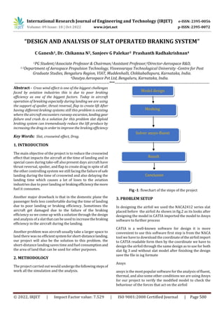
- 1. International Research Journal of Engineering and Technology (IRJET) e-ISSN: 2395-0056 Volume: 09 Issue: 10 | Oct 2022 www.irjet.net p-ISSN: 2395-0072 © 2022, IRJET | Impact Factor value: 7.529 | ISO 9001:2008 Certified Journal | Page 500 “DESIGN AND ANALYSIS OF SLAT OPERATED BRAKING SYSTEM” C Ganesh1, Dr. Chikanna N2, Sanjeev G Palekar3 Prashanth Radhakrishnan4 1PG Student,2Associate Professor & Chairman,3Assistant Professor,4Director-Aerospace R&D, 1-3Department of Aerospace Propulsion Technology, Visvesvaraya Technological University -Centre for Post Graduate Studies, Bengaluru Region, VIAT, Muddenhalli, Chikkaballapura, Karnataka, India. 4Dautya Aerospace Pvt Ltd, Bengaluru, Karnataka, India. ---------------------------------------------------------------------***--------------------------------------------------------------------- Abstract - Cross wind effect is one of the biggest challenges faced by aviation industries this is due to poor braking efficiency as one of the biggest factors. Today in aircraft operation of breaking especially during landing we are using the support of spoiler, thrust reversal, flap to create lift After having different braking systems still this problem is existing where the aircraft encounters runway excursion, landing gear failure and crush As a solution for this problem slat diploid braking system can tremendously reduce the lift produce by increasing the drag in order to improve the braking efficiency Key Words: Slat, crosswind effect, Drag. 1. INTRODUCTION The main objective of the project is to reduce the crosswind effect that impacts the aircraft at the time of landing and in special cases during take-off also present days aircraft have thrust reversal, spoiler, and flap to create drag in spite of all the other controlling system we still facing the failureofsafe landing during the time of crosswind and also delaying the landing time which causes a lot of loses to the aviation industries due to poor landingorbrakingefficiencythemore fuel it consumes. Another major drawback is that in the domestic plane the passenger feels less comfortable during the time of landing due to poor landing or braking efficiency. Sometimes the aircraft get damaged due to the failure of the braking efficiency so we come up with a solution through the design and analysis of a slat that can be used to increasethebraking efficiency in the aircraft during the landing. Another problem was aircraft usually take a larger space to land there was no efficientsystemforshort-distancelanding. our project will also be the solution to this problem. the short-distance landing saves time and fuel consumptionand the area of land that can be used for other purposes. 2. METHODOLOGY The project carried out would undergothefollowingstepsof work all the simulation and the analysis. Fig -1: flowchart of the steps of the project 3. PROBLEM SETUP In designing the airfoil we used the NACA2412 series slat placed before the airfoil As shown in fig.2 as its looks after designing the model in CATIA imported the model to Ansys software to further process CATIA is a well-known software for design it is more convenient to use this software first step is from the NACA tool we have to download the coordinateof theairfoil import to CATIA readable form then by the coordinate we have to design the airfoil through the same design as to use for both slat fig 3 and without slat model after finishing the design save the file in isg formate Ansys ansys is the most popular software for the analysis of fluent, thermal, and also some other conditions we are using Ansys for our project to verify the modified model to check the behaviour of the forces that act on the airfoil Model design Meshing Solver ansys-fluent Result Conclusion
- 2. International Research Journal of Engineering and Technology (IRJET) e-ISSN: 2395-0056 Volume: 09 Issue: 10 | Oct 2022 www.irjet.net p-ISSN: 2395-0072 © 2022, IRJET | Impact Factor value: 7.529 | ISO 9001:2008 Certified Journal | Page 501 Fig -2: NACA2412 series Airfoil without slat Fig -3: NACA2412 series Airfoil with slat Fig -4: NACA2412 series Airfoil with slat 4. MESHING Meshing is a very important part of CFD simulation. Without a proper mesh, will not be possible to get a converged solution in this project meshing has been done using ANSYS meshing feature. Initially, the mesh was checked for any mappable feasibility. This initial overview gives us a rough idea of how our mesh would be. According to this necessary mesh, control can be done according to the surface or body type. A control to the extent of managing the number of elements to be present at the specific edge or face can also be managed through mesh control. Fig -4: Details of Mesh In the meshing select the element size 2m to set select face mesh then select all the planes of the model to uniform meshing on the surface of the model then select the growth rate as 1.1 in the mesh setup click the generate .belowfig 5is the meshing of the without slat model and fig 6 denotes the with slat mode Fig -5: Meshing of Airfoil without slat Fig -6: Meshing of Airfoil with slat
- 3. International Research Journal of Engineering and Technology (IRJET) e-ISSN: 2395-0056 Volume: 09 Issue: 10 | Oct 2022 www.irjet.net p-ISSN: 2395-0072 © 2022, IRJET | Impact Factor value: 7.529 | ISO 9001:2008 Certified Journal | Page 502 5. FLUENT SETUP On starting the FLUENTsetup, theFLUENTlauncherappears providing options with 2D/3D model basedonthegeometry model and options like double precision, display mesh, etc, Additionally, the launcher also enables the user to select a number of processors that are being dedicated for the FLUENT program. The user can also set up as shown in fig 7additional cores of the Dedicated core based on the model complexity. Fig -7: FLUENT SETUP The mesh will be automatically loaded into the setup and creates automated partitions, zone, and necessaryboundary condition which will include our named selection that we have created in the meshing stage. The first step to being done upon loading the mesh into the FLUENT setup is to check the mesh integrity loaded onto the setup. This is a preliminary check that has to be done in order to avoid errors (in case) in the late stage. Click the check button in the general settings of the task plane and wait till it message appears on the console of the client which states the mesh has no error and the setup is carried forward. Then we will configure the model that is to beconsideredfor the setups i.e., Energy, Viscous, and species model. viscous SST k omega then click the komega 2eq then click ok is shown in fig8 Fig -8 Solution Setup Of Model After the setup of the solution after selecting the report definition in that select, the force of lift and drag coefficient then create the report definition. After the report, the setup computes the solution from the inlet of the model selects initialization Then clicks on the standard initialization afterward clicks on compute from the inlet .referance frame as to be absolute. Click on initialization after the initialization clicksontherun calculation in this module set the 500 iterations andthenset the interval 10 after clicking on run. after clicking the run system take time to compute the graph of lift, drag, and residual graph after that go to the result and select the plane to create a plane on the XY plane, create a counter select the plane, and the wing region select the static pressure as to show click on save and plot as shown in fig After the model set up move and select the material in the material select air set the viscosity and density of the material as te constant and density is 1.225 than click change as shown in fig-8 Fig -9 Create material setup taskbar After the material setup go to the solution method in the sostepwiselect theshownhostepwisese is as shown in the figure select the gradient as least square node based and the pressure as second-order momentum as second-order upwind turbulent kinetic energy as second-order upwind scheme as simple
- 4. International Research Journal of Engineering and Technology (IRJET) e-ISSN: 2395-0056 Volume: 09 Issue: 10 | Oct 2022 www.irjet.net p-ISSN: 2395-0072 © 2022, IRJET | Impact Factor value: 7.529 | ISO 9001:2008 Certified Journal | Page 503 Fig -8 Solution method set up taskbar After the setup of the solution afterselectreportdefinitionin that select, the force of lift and drag coefficient then create the report definition. After the report, the setup computes the solution from the inlet of the model selects initialization Then clicks on the standard initializationafterward clickson compute from the inlet .referance frame as to be absolute. Click on initialization after the initialization clicksontherun calculation in this module set the 500 iterations andthenset the interval 10 after clicking on run. after clicking the run system take time to compute the graph of lift, drag, and residual graph after that go to the result and select the plane to create a plane on the XY plane, create a counter select the plane, and the wing region select the static pressure as to show click on save and plot. Between the solution and initializing the soultion, there is another set is report pots we have to define the cl and cd to be posted as a result . Fig -10 Run calculation set up taskbar Run calcution taskbar we have to enter the number of iteration as 500 and report interval as 10 as shown in fig9 6. RESULT AND DISCUSSION After the computation by comparing our model airfoil with slat against the model in which normal airfoil fig10 cl graph is showing that the lift is increasing in withoutsaltornormal airfoil but in our model fig11 lift is going decreases as we computed the graph. From this graph, we can say that our model has achieved the objective of the project In the below graph fig7.1 of the model without slat model shows that the lift coefficient increases for the iteration of 500 readings x-axis is the lift coefficient and y is the number of iterations. Fig -11 coefficient of lift without slat model Fig -12 coefficient of lift with slat model
- 5. International Research Journal of Engineering and Technology (IRJET) e-ISSN: 2395-0056 Volume: 09 Issue: 10 | Oct 2022 www.irjet.net p-ISSN: 2395-0072 © 2022, IRJET | Impact Factor value: 7.529 | ISO 9001:2008 Certified Journal | Page 504 Fig -13 Residuals graph of without slat model Fig -14 Residuals graph of without slat model Fig -15 Residuals graph of without slat model From the above pressure distribution of both, our model fig14 versus the normal airfoil model pressure distribution around the normal airfoil fig 15 is more compared it with our slat model due to the direct contact of air force pressure is more at the normal airfoil but in our model Pressure is cut off by the slat which increases the efficiency in the braking system of the aircraft and also helps with the safer landing and also short distance landing of aircraft. 8.CONCLUSION This project’s main objective is to reduce the lift force of the aircraft during the time of crosswind effect on the aircraft landing movement. Reduce the crosswind effect and allows the aircraft to smooth and safe landing as per our objective the lift is considerably decreased. while the without slat model has generated the lift by this result we can conclude that the experiment has shown a positive result towards the objective of the project this result can be not only applicable during the crosswind effect but also in the time of failure of another control unit. This slat model can also be used for the short-distance landing of aircraft thereby reducing the time of landing and also the fuel consumption of the aircraft. And the space required during the landing. After the project outcome further, we have test the model on WindTunnel for more confirmation and also rectifies the problem what are faced during the landing of the aircraft The project as gives a positive result towards the objective . satisified the condition has now REFERENCES. [1] ”Drag Assessment of a High Performance Aircraft using System Identification Techniques” Khadeeja Nusrath, Jatinder Singh and Basappa National Aerospace Laboratories, CSIR, Bangalore-560017, India [2] Crosswind Landings in General Aviation: A Modified Method of Reporting Wind Information to the PilotMatt Ebbatson, Don Harris, and Steve Jarvis Department of Human Factors Cranfield University, Bedford, United Kingdom [3] The effect of flap-end additions on aircraft trailing vortices W. R. Graham and T. Berteny Department of Engineering, University of Cambridge, UK L. David Laboratoire d’Etudes Aérodynamiques, Université de Poitiers, France [4] Effect of Leading-Edge Slats at Low Reynolds Numbers Lance W. Traub and Mashaan P. Kaula †Aerospace Engineering Department, Embry Riddle Aeronautical University, Prescott, AZ 86301, USA;
- 6. International Research Journal of Engineering and Technology (IRJET) e-ISSN: 2395-0056 Volume: 09 Issue: 10 | Oct 2022 www.irjet.net p-ISSN: 2395-0072 © 2022, IRJET | Impact Factor value: 7.529 | ISO 9001:2008 Certified Journal | Page 505 [5] Aircraft Braking System 1Shruti Nair, 2Shreya Nair 1,2Dept. of Mechanical and Automation Engineering, Indira Gandhi Delhi Technical University for Women, Delhi, India [6] Wind-tunnel and CFD investigations of UAV landing gears and turrets – Improvements in empirical drag estimation Falk Götten a,b,∗,Marc Havermanna,Carsten Braun a, Matthew Marino b, Cees Bil b a Department of Aerospace Engineering,FHAachenUniversityofApplied Sciences, Hohenstaufenallee 6,Aachen,52064,Germany b School of Engineering,RMITUniversity,264PlentyRd, Bundoora 3083, Australia [7] Wind-tunnel and CFD investigations of UAV landing gears and turrets – Improvements in empirical drag estimation Falk Götten a,b,∗,Marc Havermanna,Carsten Braun a, Matthew Marino b, Cees Bil b a Department of Aerospace Engineering,FHAachenUniversityofApplied Sciences, Hohenstaufenallee 6,Aachen,52064,Germany b School of Engineering,RMITUniversity,264PlentyRd, Bundoora 3083, Australia