IoT Based smart Battery Management System
•
0 j'aime•290 vues

https://www.irjet.net/archives/V9/i6/IRJET-V9I6219.pdf

Recommandé
Recommandé
Contenu connexe
Tendances
Tendances (20)
Similaire à IoT Based smart Battery Management System
Similaire à IoT Based smart Battery Management System (20)
Plus de IRJET Journal
Plus de IRJET Journal (20)
Dernier
Dernier (20)
IoT Based smart Battery Management System
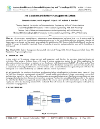
- 1. International Research Journal of Engineering and Technology (IRJET) e-ISSN: 2395-0056 Volume: 09 Issue: 06 | June 2022 www.irjet.net p-ISSN: 2395-0072 © 2022, IRJET | Impact Factor value: 7.529 | ISO 9001:2008 Certified Journal | Page 1231 IoT Based smart Battery Management System Dinesh Panicker1, Darsh Kapoor2, Prajwal S.P3, Mahesh A. Kamthe4 1 Student, Dept of Electronics and Communication Engineering, MIT-ADT University,Pune 2 Student Dept of Electronics and Communication Engineering, MIT-ADT University 3 Student Dept of Electronics and Communication Engineering, MIT-ADT University 4 Assistant Professor, Dept of Electronics and Communication Engineering, , MIT-ADT University ---------------------------------------------------------------------***------------------------------------------------------------------- Abstract – In this project, a model battery management system was developed and tested for a 1s an 3s battery pack.The parameters were sent to the cloud and data analysis wasperformed to find out the faulty cell in the battery pack. Passive cell balancing was performed, and the results were evaluatedfor a Lithium ion NMC Battery Pack of 3 cells. The cells are charged with CC-CV charger for 1s and 3s respectively. This is all modelled for an e-bike application, but the scope will be limited to a 3s battery pack Key Words: BMS- Battery Management System, IoT- Internet of Things, NMC- Nickel Manganese Cobalt Oxide, API- Application Programming Interface 1. INTRODUCTION In this project, we'll measure voltage, current, and temperature and therefore the necessary balancing circuits and protection. Then, using an Arduino Nano, we'll create A battery management system for an E-bike application. the information obtained are going to be transferred to a cloudserver with the assistance of a BOLT IoT module, and we'lluse data analysis to work out which cell within the batterypack is bad. The battery management system's balancing function is additionally a very important feature. A correct balance of the electrical battery management system will allow the battery cells to be used more efficiently and safely for extended periods of your time. We will also display the results on the Arduino serial monitor before uploading them to the cloud server via an API. Over the UART line, the system communicated with an BOLT module and transmitted data (voltage, temperature, current, SoC, and operating status) to a far-off server. Simultaneously, a command infrastructure has been developed that may stop charging and discharging from the remote server when necessary. This function also adds an IoT capability to the system. the info that the battery management system sends to the remote server provides information about the system's supply and allows the balancing function to be evaluated. This IoT feature also allows you to regulate load output and consider the charging process. 2. BLOCK DIAGRAM Fig 1: Block Diagram
- 2. International Research Journal of Engineering and Technology (IRJET) e-ISSN: 2395-0056 Volume: 09 Issue: 06 | June 2022 www.irjet.net p-ISSN: 2395-0072 © 2022, IRJET | Impact Factor value: 7.529 | ISO 9001:2008 Certified Journal | Page 1232 The figure above depicts the overall block diagram of our project. The Arduino Nano microcontroller first measures the voltage, current, and temperature of each cell. Theparameters are then transmitted to a BOLT/ESP8266 IoT board, which transmits them to the cloud server. The battery pack has been subjected to some analysis using the NMC Cell Chemistry's OCV-SOC look-up table. The faulty cell is then detected, and the user is notified. The cloud analytics uses the OCV-SOC dataset to identify the faulty cell and alerts the user. 3. CIRCUIT DIAGRAM Fig 2: Circuit Diagram In our Project we have taken a battery pack of 3 cells of 3.5~3.6v each. For voltage & current detection of the battery pack, we have connected an ACS712 hall-effect sensor & then it is connected to the microcontroller. For voltage detection formula used is: Voltage = Input vtg / 1023 * reference voltage (Vref) Here Vref is 0.000447V (or 4.47mV) since the VCC of the arduino is 4.68V & for current detection, the formula used is: Current = (o/p Voltage-offset voltage)/sensitivity Here sensitivity ranges from 66 mV/A to 185 mv/A. The offset voltage is 490 mV For temperature sensing, we had used a thermistor. Input is given to the analog pin A8, the microcontroller converts it to the digital output using a suitable equation and it displays it on the LCD(simulation). In hardware, we’re displaying it on the BOLT IoT cloud For displaying values are had used 16 x 2 alphanumeric LCD(simulation). Coming to the battery protection part, we had used a relay for switching & grounding the circuit. We had programmed it in such a way that when the Temperature of the battery pack is less than 10 deg or greater than 60 deg, then the relay grounds thecircuit. The actual hardware for protection consists of theDW01A IC and some 06N03LA Power MOSFETs which are both included in the 3s battery balancing + protection board and in the TP4056 IC(for 1s configuration)
- 3. International Research Journal of Engineering and Technology (IRJET) e-ISSN: 2395-0056 Volume: 09 Issue: 06 | June 2022 www.irjet.net p-ISSN: 2395-0072 © 2022, IRJET | Impact Factor value: 7.529 | ISO 9001:2008 Certified Journal | Page 1233 4. LITERATURE SURVEY We have referred to the following research papers forour project. The first paper is the main one which gave us a general idea of the BMS development. 5. SYSTEM SPECFICATIONS Hardware Specifications: 1. Arduino Nano Board Management System” in SasTech Journal Volume 11, Issue 2, Sept 2012 3 lker Aydn, Özgür Üstün “A Basic Battery Management System Design with IoT Feature for LiFePO4 Batteries” in IEEE International Conference on Electrical and Electronics Engineering (ELECO) Implementation ofIoT in BMS 4 Nathan Scharich, Brandon Schniter, Anthony Herbert, and Md. Shafiul Islam, “Battery Management System Using Arduino” in 2017 IEEE Technology &Engineering Management Conference (TEMSCON) Arduino Implementation ofBMS 5 Balakumar Balasingam 1,* , Mostafa Ahmed 1 and Krishna Pattipati 2,“Battery Management Systems—Challenges and Some Solutions” in Energies 2020 BMS faults andsafety Sr. No Publications andAuthor Title Taken 1 Yow-Chyi Liu1 and Shyue- BinChang2,“Design and Implementation of aSmartLithium- Ion Battery Capacity Estimation System for E- Bike” in World Electric Vehicle Journal Vol. 4 Battery Management with Lithium-Ion cellsfor an E-bikeapplication 2 Namith T, Preetham Shankpal, “Design and Development of Efficient Battery Charging and Cell Balancing for Battery Circuit Design forthe BMS Table -1: Literature Survey
- 4. International Research Journal of Engineering and Technology (IRJET) e-ISSN: 2395-0056 Volume: 09 Issue: 06 | June 2022 www.irjet.net p-ISSN: 2395-0072 © 2022, IRJET | Impact Factor value: 7.529 | ISO 9001:2008 Certified Journal | Page 1234 2. Bolt IoT module 3. TP4056 battery charger IC 4. Shunt resistor Load 5. DW10A Protection IC 6. NTC 10k thermistor 7. 3S 10A 12V 18650 Lithium Batterybalancing/protection board 8. LM2596HVS Buck converter for 3s 9. Cell weld strips 10. Battery Holder Software Specifications: 1. Proteus 2. Arduino IDE 3. Bolt Platform 6. DESIGN, DEVELOPMENTS AND DRAWINGS 6.1 Features of and working principle of ACS712 inour circuit: Fig 3: ACS712 pinout Indirect sensing is used by the ACS712 current sensor. When current flows across the wire, direct sensing uses Ohm's law to calculate the free fall across it. In indirect sensing, the magnetic flux is calculated using Faraday's law or the Ampere law. This IC detects this using a low-offset Hall sensor. This sensor is located on the IC's surface along a copper conduction path. It's a copper strip that connects the sensor's IP+ and IP- pins internally. When current flows through this copper conductor, it generates a magnetic flux, which the Hall Effect sensor detects. The hall effect sensor produces voltage proportional to the sensed force field, which is used to generate live current.
- 5. International Research Journal of Engineering and Technology (IRJET) e-ISSN: 2395-0056 Volume: 09 Issue: 06 | June 2022 www.irjet.net p-ISSN: 2395-0072 © 2022, IRJET | Impact Factor value: 7.529 | ISO 9001:2008 Certified Journal | Page 1235 6.2 BOLT IoT features and Working: Fig 4: BOLT IoT contents The BOLT IoT development board includes the ESP-12E module, which contains a chip with a Tensilica Xtensa 32-bit LX106 RISC microprocessor. This microprocessor supports RTOS and operates at an adjustable clock frequency of 80MHz to 160MHz. To store data and programmes, the BOLT IoT has 128 KB of RAM and 4MB of nonvolatile storage. Its high processing power, combined with built-in Wi- Fi/Bluetooth and Deep Sleep Operating features, makes it ideal for IoT projects. The primary function of this device isto send data to the cloud and perform data analysis on the cloud. The BOLT IoT will be powered by a Micro USB jack and a VIN pin (External Supply Pin). It has interfaces for UART, SPI, andI2C. 6.3 Actual Circuit Connections Fig 5: Hardware connections The circuit connection for the 1s battery is shown above. The voltage of the battery is measured directly through the wire. The current is measured using an ACS712 current sensor. The temperature of the system is measured using an NTC Thermistor. These parameters are then sent to the cloud for analysis. The faulty cell is detected and the user is notified.This experiment used a 2ohm, 10W shunt that can discharge the cell in less than 30 minutes.
- 6. International Research Journal of Engineering and Technology (IRJET) e-ISSN: 2395-0056 Volume: 09 Issue: 06 | June 2022 www.irjet.net p-ISSN: 2395-0072 © 2022, IRJET | Impact Factor value: 7.529 | ISO 9001:2008 Certified Journal | Page 1236 6.4 3S Battery Protection and Balancing Board 10AWorking: Fig 6: Battery Protection and Balancing Board connections • The connections are strictly in accordance with the wiringdiagram • It will have output once we have charged the primary line. • This circuit includes the 06N03LA Power MOSFET, which isused for passive cell balancing. • It also includes the DW01C IC Module, which providesovervoltage/overcurrent protection. 6.5 DC-DC Buck Converter 4.5-50V to 3-40VAdjustable Step Down Power Module: The LM2596HVS module is a high input voltage variant of the LM2596 Module. The LM2596HV module is a buck converter module with an input voltage range of 4.5 to 50 volts and an output voltage range of three to 40 volts. This variable output can be adjusted using the on-board multi- turn potentiometer. This will help charging our 3s battery pack. Fig 7: LM2596HVS Buck converter module 6.6 Discharger board Schematics and PCB The Discharger board is designed for the 1s battery configuration. We have used IRF544 MOSFET to dissipate the heat and balance the voltage properly. A Shunt output is connected to the board along with a 18650 battery. We also have an operational amplifier to measure the current discharged in the circuit. This arrangement uses a direct current measurement method with a sense resistor and external amplifier (opamp in this case) to determine the current. We also have reserved spaces for someoptocouplers if we want to use higher currents.
- 7. International Research Journal of Engineering and Technology (IRJET) e-ISSN: 2395-0056 Volume: 09 Issue: 06 | June 2022 www.irjet.net p-ISSN: 2395-0072 © 2022, IRJET | Impact Factor value: 7.529 | ISO 9001:2008 Certified Journal | Page 1237 Fig 8: Discharger board schematics Fig 9: Discharger board PCB 7. RESULTS 7.1 SIMULATION RESULTS: Fig 10: Voltage and Current Monitoring
- 8. International Research Journal of Engineering and Technology (IRJET) e-ISSN: 2395-0056 Volume: 09 Issue: 06 | June 2022 www.irjet.net p-ISSN: 2395-0072 © 2022, IRJET | Impact Factor value: 7.529 | ISO 9001:2008 Certified Journal | Page 1238 The circuit was simulated in proteus along with an ACS712current sensor and a 10k NTC thermistor. The voltage was measured directly by the A0 pin of the Arduino Nano Microcontroller, current by the A1 pin and temperature bythe A2 pin. In simulation only we’ve included a relay circuitfor protection, which would not be necessary in the practical hardware. Fig 11: Temperature Monitoring 7.1 HARDWARE RESULTS: Fig 12: Discharger PCB board results
- 9. International Research Journal of Engineering and Technology (IRJET) e-ISSN: 2395-0056 Volume: 09 Issue: 06 | June 2022 www.irjet.net p-ISSN: 2395-0072 © 2022, IRJET | Impact Factor value: 7.529 | ISO 9001:2008 Certified Journal | Page 1239 Fig 13: Charging Hardware circuit In the charging hardware, we’ve implemented it using a TP4056 IC and charged this single cell battery. There are provisions for voltage/current spikes as it contains theDW01A IC. Fig 14: Results displayed on the serial monitor are sent tothe cloud Fig 15: 3s cell balancing + protection
- 10. International Research Journal of Engineering and Technology (IRJET) e-ISSN: 2395-0056 Volume: 09 Issue: 06 | June 2022 www.irjet.net p-ISSN: 2395-0072 © 2022, IRJET | Impact Factor value: 7.529 | ISO 9001:2008 Certified Journal | Page 1240 The 3s cell battery pack is protected by the charger protection board, which offers both cell balancing and protection. The cells are charged by a LM2596HVS buck converter module. This arrangement ensures all the cells are equally charged and there are no voltage/current spikes. 8. CONCLUSION The developed system is used for a 3s as well as for a 1s battery pack system. The voltage, current, temperature andSoC values were sent to the cloud. In our system, we have implemented IoT and data analytics through cloud, which helped us study and observe each parameter and behavior of each battery in detail. Using this data, we can deduce how each cell in the battery pack is performing, not as a collective, but individually, which will help isolate any problem causing cells. Fault codes have also been implemented which will be displayed on the cloud so that even the end user can understand in short what might be the problem. We can even prevent many accidental fires due totemperature or external stimulus with the help of our system. The charging and discharging of both 3s and 1s cells have been shown and thus we have built a battery pack of the required configuration. ACKNOWLEDGEMENT The satisfaction that accompanies the successful completion of the task would be put incomplete without the mention ofthe people who made it possible, whose constant guidanceand encouragement crown all the efforts with success. It is my greatest pleasure to thank Prof. Dr. Virendra V. Shete (Vice-Principal, MIT SOE and Head, Department of Electronics and Communication, MIT ADT University) for providing us heart full encouragement support and allowing us to work in such a resourceful lab of this esteemed institute and thereby fulfilling one of my dreams. I whole heartedly thank my project guide Prof. Mahesh A. Kamthe for his consistent guidance, expert academic and support throughout the project, without his great concepts & inspiration it would have been impossible. I thank my parents for their emotional and financial support which they provided during this project. We show gratitude to our Honourable Principal Prof. Dr. Kishore Ravande, for having provided all the facilities and support. I thank to all faculties who directly and indirectly helped usin the completion of this project. Fig 16: 3s cell charging
- 11. International Research Journal of Engineering and Technology (IRJET) e-ISSN: 2395-0056 Volume: 09 Issue: 06 | June 2022 www.irjet.net p-ISSN: 2395-0072 © 2022, IRJET | Impact Factor value: 7.529 | ISO 9001:2008 Certified Journal | Page 1241 REFERENCES [1] Yow-Chyi Liu and Shyue-Bin Chang,“Design and Implementation of a Smart Lithium-Ion Battery Capacity Estimation System for E-Bike” in World Electric Vehicle Journal Vol.4 [2] Namith T, Preetham Shankpal, “Design and Development of Efficient Battery Charging and Cell Balancing for Battery Management System” in SasTech Journal Volume 11, Issue 2,Sept 2012 [3] lker Aydn, Özgür Üstün “A Basic Battery Management System Design with IoT Feature for LiFePO4 Batteries ” in IEEE International Conference on Electrical and Electronics Engineering (ELECO) [4] Nathan Scharich, Brandon Schniter, Anthony Herbert, and Md. Shafiul Islam, “Battery Management System Using Arduino” in 2017 IEEE Technology & Engineering Management Conference (TEMSCON) [5] Balakumar Balasingam, Mostafa Ahmed and Krishna Pattipati,“Battery Management Systems—Challenges and some solutions” in Energies 2020 [6] YANG Xu , SHEN Jiang and TONG XIN Zhang, “Research and design of lithium battery management system for electric bicycle based on Internet of things technology ” in 2019 Chinese Automation Congress (CAC) [7] Goals for Advanced Batteries for EVs; United States Council for Automotive Research LLC: Southfield, MI, USA,2009; Available online: http://www.uscar.org/commands/files_download. php?files_id=27 (assessed on 1 August 2011). [8] Stuart, T.; Fang, F.; Wang, X.P.; Ashtiani, C.; Pesaran, A. Amodular battery management system for HEVs. Future Car Congress 2002, doi:10.4271/2002-01-1918. [9] Andrea, D. Battery Management Systems for Large Lithium Ion Battery Packs, 1st ed.; Artech House: London, UK, 2010; pp. 22–110. [10] Meissner, E.; Richter, G. Battery monitoring and electrical energy management precondition forfuture vehicle electric power systems. J. Power Sources 2003,116, 79–98. [11] Gold, S. A PSPICE Macromodel for Lithium-Ion Batteries. In Proceedings of IEEE the Twelfth Annual Battery Conference on Applications and Advances, Long Beach, CA,USA, 14–17 January 1997; pp. 215–222. [12] DS2726 Datasheet Rev 3. MAXIM 5-Cell to 10-Cell Li+ Protector with Cell Balancing; Maxim Integrated Products, Inc.: Sunnyvale, CA, USA, 2010; Available online: http://datasheets.maxim-ic.com/en/ds/DS2726.pdf (accessed on 1 August 2011). [13] BQ78PL114 Datasheet. PowerLAN Gateway Battery Management Controller with PowerPump Cell Balancing; Texas Instruments Inc.: Dallas, TX, USA, 2009; Available online:http://www.ti.com/lit/ds/symlink/bq78pl114.pdf (accessed on 1 August 2011). [14] Vishal Sapre, “Essentials of a Battery Management System” in Tech Future section of the Electronics for You Magazine May 2022 [15] Yinjiao Xing , Eden W. M. Ma, Kwok L. Tsui and MichaelPecht, “Battery Management Systems in Electric and Hybrid Vehicles” in energies journal 2011 [16] Martin Bata and David Mike, “Battery Management Hardware Design for a Student Electric Racing Car” in Elsevier IFAC Conference Paper [17] Yiu, Nicholas. Jing, Linda. Yeh, Yen. He, Katherine. Zheng, Eric. “State of Batteries Report 2020.” BatteryBits, 16 January 2021. Web. Date accessed.