Study of Ball Valve and Design of Thickness of Shell and Flange
•
0 j'aime•82 vues

This document describes the design and analysis of a ball valve shell and flange to withstand pressures of 20 bar and 35 bar. CAD models of the ball valve shell and flange were created in CATIA V5 and analyzed in ANSYS to evaluate stresses. The design was able to withstand the original 20 bar pressure requirement. When the pressure requirement increased to 35 bar, the flange design was modified to a Class 300 flange as per ASME standards, but the shell thickness did not need to change. Stress analysis confirmed the designs could withstand the pressures without exceeding allowable stress limits.

Recommandé
Contenu connexe
Tendances
Tendances (16)
Similaire à Study of Ball Valve and Design of Thickness of Shell and Flange
Similaire à Study of Ball Valve and Design of Thickness of Shell and Flange (20)
Plus de IRJET Journal
Plus de IRJET Journal (20)
Dernier
Dernier (20)
Study of Ball Valve and Design of Thickness of Shell and Flange
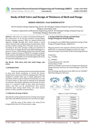
- 1. International Research Journal of Engineering and Technology (IRJET) e-ISSN: 2395-0056 Volume: 04 Issue: 10 | Oct -2017 www.irjet.net p-ISSN: 2395-0072 © 2017, IRJET | Impact Factor value: 5.181 | ISO 9001:2008 Certified Journal | Page 300 Study of Ball Valve and Design of Thickness of Shell and Flange AKSHAY CHOUGUL1, Prof. RAMESH KATTI2 1M.Tech Student (Design Engineering), KLE Dr. M S Sheshgiri College of Engineering and Technology, Belagavi, Karnataka, India 2Professor, Department of Mechanical Engineering, KLE Dr. M S Sheshgiri College of Engineering and Technology, Belagavi, Karnataka, India ---------------------------------------------------------------------***------------------------------------------------------------------- Abstract - Ball valves are widely used industrial fittings for the construction of oil and gas products transportation facilities (piping systems). They are quarter-turned (90 degrees), straight through flow valves having a round closure element with complementing rounded seats, which permits uniform sealing stress. The type of seat can vary according to the valve pressure rating and materials of construction. To design the ball valve shell and flange for a pressure 35 bar. CAD modeling of Ball Valve Shell & Flange design is made by means of CATIA V5 computer program Static analysis of the Ball Valve Shell body and Flange design is performed using ANSYS 14.5 to find the highestsafestress for equivalent payload/pressure Key Words: Ball valves, ball valve shell, flange, safe stress 1. INTRODUCTION Valves are mechanical devices particularlyintended to stop, start, blend, coordinate, or control the stream, temperature or pressure of fluid in a pipingsystem. Theyare designed to handle either gas or liquid application. The operation of valves may be required continuously as in case of control valves, or they may be required to be operated occasionally. The design, application and function of valves arrive in a extensive range of sizes, style and pressure classes, and they can be manufactured from several materials types among which brass, iron, steel, bronze, plastic, or from a number of special alloys. 1.1 Objectives & Scope of Work The objective of the proposed work is to design and analyze Ball Valve with different pressures for structural strength. And the scope of this study is for using 20 bar designed ball valve for 35 bar pressure range: 2. Design of Ball Valve Flange and Shell Body Design of Flange for 20 bars (2MPa) It is designed as per ASME/ANSI standardsfordesignofPipe Flanges & Flanged Fittings- ASME B16.5. Material selection:-the material selected A216 WCC from ASTM STD. as a material for flanges as well as for shell. Material Group(1.2)A216 WCC(C-Mn-Si)(Casting),Material Properties:- = 275MPa =485MPa Youngs Modulus (E) = 190 GPA Poisson Ratio= 0.287 Selection of Flange: From Pressure-Temperature Rating for Flange selection, and hence the selected flange is Class 150 Flange. Here, the flange specifications from ANSI 16.5 for 150/NB3” Weld-Neck flange for Ball valve. Figure 2.1 Class 150 Flanges NB 80 mm OD 191mm X 108mm G 127mm T 23.9mm B1 78mm T1 69.9 mm A 88.9 mm R 9.7 mm No. of Bolts 04 PCD 152.4mm
- 2. International Research Journal of Engineering and Technology (IRJET) e-ISSN: 2395-0056 Volume: 04 Issue: 10 | Oct -2017 www.irjet.net p-ISSN: 2395-0072 © 2017, IRJET | Impact Factor value: 5.181 | ISO 9001:2008 Certified Journal | Page 301 Hole Diameter 19 mm h2 (Neck height) 19 mm = 275MPa Fos = 04 Allowable stress (f) = 68.75MPa Formulae: ------ (eqn 1) Where, a- Radius of PCD, 76.2mm µ-Poisson’s ratio-0.278, P-Pressure acting, 20bar (0.2039Kgf/mm2) f- Allowable stress, 68.75MPa (7.0105 Kgf/mm2) t- Thickness of flange. Pitch circle diameter measured is 152.4mm By substituting above values in formulae we get thickness, t = 14.408 mm Selected Flange thickness is t= 23.9mm > 14.4 mm. Design is safe. Design of Shell for 20 bars (2MPa) The design as per ASME/ANSI standards for design of pipe Flanges & ASME B16.5 Material Properties:- = 275MPa = 485MPa Young’s Modulus (E) = 190 GPA Poisson Ratio= 0.278 Design of shell:- = 275MPa FoS = 04 Allowable stress= 68.75MPa E= 190GPa P= 20Bar (2MPa) d= 78mm (Flange ID and Cylindrical Shell end ID) D= 106mm (Spherical Shell ID) For spherical shell, Hoop stress is; ------- (eqn 2) t1= 0.77mm But, it is an open shell with a cylindrical end, So, we apply Bernie’s Principle, ----- (eqn 3) t2= 1.161 mm The cylindrical end thickness= 5.45mm to align with flange neck thickness. And shell body thickness as 8mm including corrosion allowance as 3mm. t= 8mm> t1 & t2, Hence Design is safe. Where, P - Working pressure = 2MPa (0.2039 kg-f/mm2), D – Maximum inner diameter of shell-106 mm, Constant – 3.7 (constant of material) Allowable stress (f) = 68.75MPa Formulae: --- (eqn 4) t3= 4.4988 mm So, t & t2 > t3 So, the selected shell thickness as 8mm and cylindrical end thickness as 5.45mm. Requirement Check above designed Ball Valve for35 bar pressureofwater through a pipe of NB=3” (80mm) at 25oC. Given data shall be same only pressure has been increased, Design of Flange for P = 35bar (3.5MPa): Where, a- Radius of PCD, 76.2mm µ-Poisson’s ratio-0.278, P-Pressure acting, =3.5MPa (0.3569Kgf/mm2) f- Allowable stress, 68.75MPa (7.0105 Kgf/mm2) t- Thickness of flange. By substituting above values in eqn 1 we get thickness, t = 19.0622mm Selected Flange thickness is t= 23.9mm > 14.4 mm. Design is safe. But, as per Pipe Flange & Flanged Fitting – ASME B16.5, For pressure above 19.8 bar 150 flanges cannot be used. Pressure-Temperature Rating, select Class 300 Flange with NB=80mm
- 3. International Research Journal of Engineering and Technology (IRJET) e-ISSN: 2395-0056 Volume: 04 Issue: 10 | Oct -2017 www.irjet.net p-ISSN: 2395-0072 © 2017, IRJET | Impact Factor value: 5.181 | ISO 9001:2008 Certified Journal | Page 302 Class 300 Flanges NB 80 mm OD 210mm X 117mm G 127mm T 28.4mm B1 78mm T1 79.2mm A 88.9 mm R 9.7 mm No. of Bolts 08 PCD 168 mm Hole Diameter 22 mm h2 (Neck height) 19 mm = 275MPa FoS = 04 Allowable stress (f) = 68.75MPa Where, a- Radius of PCD, 84mm µ-Poisson’s ratio-0.278, P-Pressure acting, 35bar (0.3569Kgf/mm2) f- Allowable stress, 68.75MPa (7.0105Kgf/mm2) t- Thickness of flange. Pitch circle diameter measured is 168 mm. By substituting above values in eqn 1we get thickness, t = 21.013 mm Selected Flange thickness is t= 28.4mm > 21.013 mm. Design is safe. Design of Shell for 35 bars (3.5MPa):- Given: = 275MPa FoS = 04 Allowable stress= 68.75MPa E= 190GPa P= 35Bar (3.5MPa) d= 78mm (Flange ID and Cylindrical Shell end ID) D= 106mm (Spherical Shell ID) For spherical shell, we know Hoop stress is; From eqn 2 t1= 1.349 mm But, it is an open shell with a cylindrical end, So, apply Bernie’s Principle, from eqn 2 t2= 2.068 mm So, make the cylindrical end thickness= 5.45mm to align with flange neck thickness. And shell body thickness as 8mm including corrosion allowance as 3mm. t= 8mm> t1 & t2, Hence Design is safe. Where, P - Working pressure = 3.5MPa (0.3569 kg-f/mm2), D – Maximum inner diameter of shell-106 mm, Constant – 3.7 (constant of material) Allowable stress (f) = 68.75MPa From eqn 4, t3= 5.099 mm So, t & t2 > t3; hence, Design is Safe. The same valve is used for 35bar pressure it has been found that it does not fail. But as per ASME safety norms we have used flange of higher pressure rating that is 300. & no need to change the shell body thickness. 3. Geometry Detail Fig.3.1 Flange 150 NB 3” Fig.3.2 Shell Model Fig.3.3 Flange 300 model NB 3”
- 4. International Research Journal of Engineering and Technology (IRJET) e-ISSN: 2395-0056 Volume: 04 Issue: 10 | Oct -2017 www.irjet.net p-ISSN: 2395-0072 © 2017, IRJET | Impact Factor value: 5.181 | ISO 9001:2008 Certified Journal | Page 303 4 Material Properties of Ball Valve Table 4.1 Material Properties 5. Analysis Fig.5.1 Mesh Model of Flange (Pressure=2MPa) Von-Mises stress in flange for 2MPa pressure 15.782MPa Total deformation in flange for 2MPa pressure 0.0017832 mm Fig.5.2 Flange 150 von-mises stress for 2MPa Fig.5.3 Flange 150 Total Deformation for 2MPa (Pressure=2MPa) Von-Mises stress in Shell for 2MPa pressure 14.557MPa Total deformation in Shell for 2MPa pressure 0.0013204 mm Fig.5.4 Shell Mesh Model Fig.5.6 Flange 150 Total Deformation for 2MPa (Pressure=2MPa) Fig.5.7 Shell Von Mises Stress
- 5. International Research Journal of Engineering and Technology (IRJET) e-ISSN: 2395-0056 Volume: 04 Issue: 10 | Oct -2017 www.irjet.net p-ISSN: 2395-0072 © 2017, IRJET | Impact Factor value: 5.181 | ISO 9001:2008 Certified Journal | Page 304 Fig.5.8 Shell Total Deformation (Pressure=3.5MPa) Von-Mises stress in flange for 3.5MPa pressure 27.618MPa Total deformation in flange for 3.5MPa pressure 0.0031207 mm Fig.5.9 Flange 150 Von Mises stress for a load of 35 bar (3.5MPa) Fig.5.10 Flange 150 Total Deformation for a load of 35 bar (3.5MPa) (Pressure=3.5MPa) Von-Mises stress in flange #300 for 3.5MPa pressure 27.122MPa Total deformation in flange #300 for 3.5MPa pressure 0.0031233 mm Fig.5.11 Mesh Model of Flange 300 Fig.5.12 Flange 300 Von Mises stress for 3.5MPa Fig.5.13 Flange 300 Total Deformation for 3.5 Mpa
- 6. International Research Journal of Engineering and Technology (IRJET) e-ISSN: 2395-0056 Volume: 04 Issue: 10 | Oct -2017 www.irjet.net p-ISSN: 2395-0072 © 2017, IRJET | Impact Factor value: 5.181 | ISO 9001:2008 Certified Journal | Page 305 (Pressure=3.5MPa) Von-Mises stress in Shell for 3.5 MPa pressure 25.474 MPa Total deformation in Shell for 3.5 MPa pressure 0.0023107 mm Fig.5.14 Shell Von Mises stress for pressure of 3.5 MPa Fig.5.15 Shell Total Deformation for pressure of 3.5 MPa It has been observed that in none of above cases equivalent/Von-mises stress doesn’t exceed the allowable stress limit as 68.75 MPa. 3. CONCLUSIONS So, it can be concluded that the design for 20 bars is safe. Current designed Ball Valve can also be used for 35 bar pressure. As per ASME standard, Flange should be used of class 300 for pressures above 20bars, suchasfor35 bars. In future, DOE can be done to optimize the mass & other parameter by changing material tocomposite & changing geometric parameters. The cylindrical shell body can also be designed and analysis can be performed in both cases. REFERENCES Book [1] Khurmi R. S. and Gupta J. K. “Machine Design” first edition; Eurasia Publishing House Private Limited pages (310-315). [2] Norton R. L. “Machine Design”third edition;Pearson Education Ltd. pages (454-457,621-624). Papers [1] Ming-Jyh Chern,Chin-ChengWang,Chen-HsuanMa., performance tests and flow visualisation of ball valves, Journal of experimental thermal and fluid sciences 31(2007)505-512. [2] Janusz Rogula.a, The influence of seat fatigue test on the leakage in ball valve, Journal of Procedi Engineering 39(2012)91-97. [3] A.Tudor, R.Nehriu, I.Radu, V.Dumitru, A Wear study case of ceramic ball seat valve, Tribology in industry, Volume 25, no 3&4, (2003) 83-88. [4] Yogesh G, Dr.Vilas R.K, Vijay M, Modeling and Simulation of valve coefficients and cavitation characteristic in ball valves, Proceeding of the International Conferences on Fluid mechanics and Fluid power December 16-18, 2010. [5] Ming-Jyh Chern, Chih-Cheng Wang, Controlling of volumetric flow rate of ball valves by V-ports, journal of fluid engineering may Vol-126(2004), 471-481. [6] Ming-Jyh Chern, Chih-Cheng Wang, Effect of control device on flow in ball valve, TransactionoftheAero nautical and Astro nautical Society of the Republic of China. [7] Thananchai Leephakpreeda, Design factor for “linear” ball valve, theoretical and experimental study, songklanakarin in J. sci. Technol., 27,(2005), 353-361.