Soumettre la recherche
Mettre en ligne
Lecture 06 transistorremodel
•
0 j'aime
•
472 vues
I
Ismael Cayo Apaza
Suivre
circuitos electronicos
Lire moins
Lire la suite
Technologie
Signaler
Partager
Signaler
Partager
1 sur 8
Télécharger maintenant
Télécharger pour lire hors ligne
Recommandé
Lecture 07 transistor re model
Ismael Cayo Apaza
Lecture 08 hibridequivalentmodel
Ismael Cayo Apaza
Chap7part4 (2)
Chap7part4 (2)
Hmadi Mossoi
Hybrid model for Transistor, small signal Analysis
Abhishek Choksi
Hybrid model analog electronics
rakesh mandiya
BJT AC Analisi 5
BJT AC Analisi 5
Ahmad Al-Jmal
Operationamplifier
Operationamplifier
Ahmad Al-Jmal
Hybrid Transistor Model with Two Port Network
Ridwanul Hoque
5. differential amplifier
ShahbazQamar2
My mind.dot
My mind.dot
Nur Amaliah
Bipolar junction transistor characterstics biassing and amplification, lab 9
kehali Haileselassie
Differential amplifier
sarunkutti
EE 305 Project_1 The Effective External Defibrillators
kehali Haileselassie
EE201 -Chapter 4
EE201 -Chapter 4
ruhiyah
Basic Electronics 1 by Dr. Mathivanan Velumani
Mathivanan Velumani
multistage amplifier Abhishek meena
Rai Saheb Bhanwar Singh College Nasrullaganj
Voltage Divider Bias - BJT
DoCircuits
Electronics 1 : Chapter # 07 : AC Analysis BJT
Sk_Group
36.voltage divider bias
DoCircuits
Tarun
Tarun
sameerdutta
Summing Amplifier
Summing Amplifier
Dr.Raja R
Basic characteristic of the transistor
Mazhar Laliwala
Chapter 1 ac analysis SKEE 2253
Fairul Izwan Muzamuddin
FET AMPLIFIER
FET AMPLIFIER
Jess Rangcasajo
ANALYSIS ON CLASS-A VOLTAGE FOLLOWER
Journal For Research
Linear Integrated Circuit
Chhayal Thombre Lecturer at KCE COEIT JALGAON
Lab 8 bipolar junction transistor characterstics
kehali Haileselassie
differential amplifier for electronic
Faiz Yun
Educación del siglo xxi a subir a a slideshare
Lola Sarango
SmartBits - Soluciones de negocio - www.smartbits.es
smartbits1
Contenu connexe
Tendances
5. differential amplifier
ShahbazQamar2
My mind.dot
My mind.dot
Nur Amaliah
Bipolar junction transistor characterstics biassing and amplification, lab 9
kehali Haileselassie
Differential amplifier
sarunkutti
EE 305 Project_1 The Effective External Defibrillators
kehali Haileselassie
EE201 -Chapter 4
EE201 -Chapter 4
ruhiyah
Basic Electronics 1 by Dr. Mathivanan Velumani
Mathivanan Velumani
multistage amplifier Abhishek meena
Rai Saheb Bhanwar Singh College Nasrullaganj
Voltage Divider Bias - BJT
DoCircuits
Electronics 1 : Chapter # 07 : AC Analysis BJT
Sk_Group
36.voltage divider bias
DoCircuits
Tarun
Tarun
sameerdutta
Summing Amplifier
Summing Amplifier
Dr.Raja R
Basic characteristic of the transistor
Mazhar Laliwala
Chapter 1 ac analysis SKEE 2253
Fairul Izwan Muzamuddin
FET AMPLIFIER
FET AMPLIFIER
Jess Rangcasajo
ANALYSIS ON CLASS-A VOLTAGE FOLLOWER
Journal For Research
Linear Integrated Circuit
Chhayal Thombre Lecturer at KCE COEIT JALGAON
Lab 8 bipolar junction transistor characterstics
kehali Haileselassie
differential amplifier for electronic
Faiz Yun
Tendances
(20)
5. differential amplifier
My mind.dot
My mind.dot
Bipolar junction transistor characterstics biassing and amplification, lab 9
Differential amplifier
EE 305 Project_1 The Effective External Defibrillators
EE201 -Chapter 4
EE201 -Chapter 4
Basic Electronics 1 by Dr. Mathivanan Velumani
multistage amplifier Abhishek meena
Voltage Divider Bias - BJT
Electronics 1 : Chapter # 07 : AC Analysis BJT
36.voltage divider bias
Tarun
Tarun
Summing Amplifier
Summing Amplifier
Basic characteristic of the transistor
Chapter 1 ac analysis SKEE 2253
FET AMPLIFIER
FET AMPLIFIER
ANALYSIS ON CLASS-A VOLTAGE FOLLOWER
Linear Integrated Circuit
Lab 8 bipolar junction transistor characterstics
differential amplifier for electronic
En vedette
Educación del siglo xxi a subir a a slideshare
Lola Sarango
SmartBits - Soluciones de negocio - www.smartbits.es
smartbits1
Vigural
Vigural
mivigural
3.0
3.0
contatodiib
Software Libre
Software Libre
Fercho López
Aula7 sql basico_6por_pag
anacri
RESUME2016-marcie1
RESUME2016-marcie1
Marcie Temple
Contents page conventions
Joe Hadfield
College magazine evaluation
shakeira16
Q media pack2016
Q media pack2016
shakeira16
FIAA Training - Forensic Arson Analysis and Process
Chemistry Matters Inc.
Parcial2 paredes mariajose
María José Paredes
En vedette
(12)
Educación del siglo xxi a subir a a slideshare
SmartBits - Soluciones de negocio - www.smartbits.es
Vigural
Vigural
3.0
3.0
Software Libre
Software Libre
Aula7 sql basico_6por_pag
RESUME2016-marcie1
RESUME2016-marcie1
Contents page conventions
College magazine evaluation
Q media pack2016
Q media pack2016
FIAA Training - Forensic Arson Analysis and Process
Parcial2 paredes mariajose
Similaire à Lecture 06 transistorremodel
questions on diode analysis: Assignment6
Akash Kumar Verma
Bipolar junction transistor characterstics biassing and amplification, lab 9
kehali Haileselassie
PEQPAU.pdf
PEQPAU.pdf
thamizmani s
BJT Biasing for B.Tech Ist Year Engineering
Raghav Bansal
Chapter 10.ppt Large signal transfer circuits
cbcbgdfgsdf
DC Biasing – Bipolar Junction Transistors (BJTs)
ssuserb29892
UHF Transistors
UHF Transistors
rahul kumar
project
project
piedaholic
Simulation and Experimental Verification of Single-Phase Pwm Boost -Rectifier...
IRJET Journal
dc biasing
dc biasing
Ahmad Al-Jmal
module2.pdf
module2.pdf
AnjanSengupta6
[doi 10.1002_9781118886502.ch7] Lehr, Jane; Ron, Pralhad -- Foundations of Pu...
[doi 10.1002_9781118886502.ch7] Lehr, Jane; Ron, Pralhad -- Foundations of Pu...
PKSahu6
Multisim_simulation_project_3_^0_4[1]-2.pptx
wencove9
Intro electronics laboratory
Thinh Pham Quoc
Design and simulation of high frequency colpitts oscillator based on BJT ampl...
IJECEIAES
99992505.pdf
99992505.pdf
NurHuda254477
bjt ppt project.ppt
bjt ppt project.ppt
SURYAKANTASWAIN26
Closed Loop Controlled Solar Cell Powered Embedded EZ-Source Inverter fed Ind...
IDES Editor
Simple 100 w inverter circuit
Narasimha Reddy
Chapterhj jkhjhjhjh kjhjhjhljh jhkjhjhgftf rdrd
LuisAngelLugoCuevas
Similaire à Lecture 06 transistorremodel
(20)
questions on diode analysis: Assignment6
Bipolar junction transistor characterstics biassing and amplification, lab 9
PEQPAU.pdf
PEQPAU.pdf
BJT Biasing for B.Tech Ist Year Engineering
Chapter 10.ppt Large signal transfer circuits
DC Biasing – Bipolar Junction Transistors (BJTs)
UHF Transistors
UHF Transistors
project
project
Simulation and Experimental Verification of Single-Phase Pwm Boost -Rectifier...
dc biasing
dc biasing
module2.pdf
module2.pdf
[doi 10.1002_9781118886502.ch7] Lehr, Jane; Ron, Pralhad -- Foundations of Pu...
[doi 10.1002_9781118886502.ch7] Lehr, Jane; Ron, Pralhad -- Foundations of Pu...
Multisim_simulation_project_3_^0_4[1]-2.pptx
Intro electronics laboratory
Design and simulation of high frequency colpitts oscillator based on BJT ampl...
99992505.pdf
99992505.pdf
bjt ppt project.ppt
bjt ppt project.ppt
Closed Loop Controlled Solar Cell Powered Embedded EZ-Source Inverter fed Ind...
Simple 100 w inverter circuit
Chapterhj jkhjhjhjh kjhjhjhljh jhkjhjhgftf rdrd
Plus de Ismael Cayo Apaza
Problema sust y eolica
Ismael Cayo Apaza
Eer tema 03 energia solar fotovoltaica.ppt [modo de compatibilidad]
Ismael Cayo Apaza
Eer tema 01 generalidades
Ismael Cayo Apaza
El principito
El principito
Ismael Cayo Apaza
Segundo cultura nazca
Ismael Cayo Apaza
La fuente
La fuente
Ismael Cayo Apaza
Aparamenta electrica.
Ismael Cayo Apaza
Conductores
Conductores
Ismael Cayo Apaza
Secciontecnica
Secciontecnica
Ismael Cayo Apaza
Manual electrico viakon capitulo 2
Ismael Cayo Apaza
37. secciones 370-alarmas contra incendio
Ismael Cayo Apaza
Aprueban norma técnica
Ismael Cayo Apaza
Conductores electricos
Ismael Cayo Apaza
Aprueban norma técnica
Ismael Cayo Apaza
Elec ch06bjt amplifiers
Ismael Cayo Apaza
1. el amplificador de emisor comun
Ismael Cayo Apaza
Practica3
Practica3
Ismael Cayo Apaza
Trabajo tercera ley d ela termodianamica
Ismael Cayo Apaza
Medidas de valores máximos
Ismael Cayo Apaza
Multiplicadores de escala en instrumentos de tensión y de corriente
Ismael Cayo Apaza
Plus de Ismael Cayo Apaza
(20)
Problema sust y eolica
Eer tema 03 energia solar fotovoltaica.ppt [modo de compatibilidad]
Eer tema 01 generalidades
El principito
El principito
Segundo cultura nazca
La fuente
La fuente
Aparamenta electrica.
Conductores
Conductores
Secciontecnica
Secciontecnica
Manual electrico viakon capitulo 2
37. secciones 370-alarmas contra incendio
Aprueban norma técnica
Conductores electricos
Aprueban norma técnica
Elec ch06bjt amplifiers
1. el amplificador de emisor comun
Practica3
Practica3
Trabajo tercera ley d ela termodianamica
Medidas de valores máximos
Multiplicadores de escala en instrumentos de tensión y de corriente
Dernier
Handwritten Text Recognition for manuscripts and early printed texts
Maria Levchenko
Tata AIG General Insurance Company - Insurer Innovation Award 2024
The Digital Insurer
Driving Behavioral Change for Information Management through Data-Driven Gree...
Enterprise Knowledge
Apidays Singapore 2024 - Building Digital Trust in a Digital Economy by Veron...
apidays
08448380779 Call Girls In Civil Lines Women Seeking Men
Delhi Call girls
Mastering MySQL Database Architecture: Deep Dive into MySQL Shell and MySQL R...
Miguel Araújo
Real Time Object Detection Using Open CV
Khem
Boost Fertility New Invention Ups Success Rates.pdf
sudhanshuwaghmare1
Understanding Discord NSFW Servers A Guide for Responsible Users.pdf
UK Journal
[2024]Digital Global Overview Report 2024 Meltwater.pdf
[2024]Digital Global Overview Report 2024 Meltwater.pdf
hans926745
Exploring the Future Potential of AI-Enabled Smartphone Processors
debabhi2
Bajaj Allianz Life Insurance Company - Insurer Innovation Award 2024
The Digital Insurer
Slack Application Development 101 Slides
praypatel2
CNv6 Instructor Chapter 6 Quality of Service
giselly40
Scaling API-first – The story of a global engineering organization
Radu Cotescu
Boost PC performance: How more available memory can improve productivity
Principled Technologies
Strategies for Unlocking Knowledge Management in Microsoft 365 in the Copilot...
Drew Madelung
A Year of the Servo Reboot: Where Are We Now?
Igalia
Finology Group – Insurtech Innovation Award 2024
The Digital Insurer
Histor y of HAM Radio presentation slide
vu2urc
Dernier
(20)
Handwritten Text Recognition for manuscripts and early printed texts
Tata AIG General Insurance Company - Insurer Innovation Award 2024
Driving Behavioral Change for Information Management through Data-Driven Gree...
Apidays Singapore 2024 - Building Digital Trust in a Digital Economy by Veron...
08448380779 Call Girls In Civil Lines Women Seeking Men
Mastering MySQL Database Architecture: Deep Dive into MySQL Shell and MySQL R...
Real Time Object Detection Using Open CV
Boost Fertility New Invention Ups Success Rates.pdf
Understanding Discord NSFW Servers A Guide for Responsible Users.pdf
[2024]Digital Global Overview Report 2024 Meltwater.pdf
[2024]Digital Global Overview Report 2024 Meltwater.pdf
Exploring the Future Potential of AI-Enabled Smartphone Processors
Bajaj Allianz Life Insurance Company - Insurer Innovation Award 2024
Slack Application Development 101 Slides
CNv6 Instructor Chapter 6 Quality of Service
Scaling API-first – The story of a global engineering organization
Boost PC performance: How more available memory can improve productivity
Strategies for Unlocking Knowledge Management in Microsoft 365 in the Copilot...
A Year of the Servo Reboot: Where Are We Now?
Finology Group – Insurtech Innovation Award 2024
Histor y of HAM Radio presentation slide
Lecture 06 transistorremodel
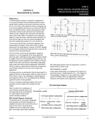
1.
© Copy Right:
Rai University 4A.273 15 ELECTRONICDESIGNTECHNOLOGY Objective: To understand the transistor re model (CE configuration). A very good morning to all of you! Well students you have already started a journey in the world of electronics and I am here to cover some of the milestones with you and guide you in every way possible by this time you are well versed with the basic concepts like intrinsic, extrinsic semiconductors, diode mechanism, transistor action and much such related topics, which your have studied in basic electronics and solid state devices and circuits. Believe me students, if your these three subjects i.e. basic electronics, solid state devices and EDLC are clear and your logics are clear your journey throughout this electronics engineering is going to be a very smooth one. You are aware with the basic construction, appearance and characteristics of transistor. Name what we have to firstly understand is the small-signal ac response of the BJT amplifier by reviewing the models most frequently used to represent the transistor in the sinusoidal domain. One of our first concerns in the sinusoidal ac analysis of transistor n/w is the magnitude of the input signal will determine where small signal or large signal techniques should be applied. There is no set dividing line between the two, but the application and the magnitude of the variables of interest relative to the scales of the devices characteristics, will usually make it quite clear which method is appropriate. Well firstly I will try to make you understand the small-scale technique and once the base is formed we can move over to large-scale applications: One thing you have to understand is that the input signal Vi is applied to the base of the transistor while the output current I0 is the collector current. The small signal ac analysis begins by removing the dc effects of Vcc and replacing the dc blocking capacitors by short circuit equivalents. The key to transistor small signal analysis is the use of equivalent circuits (models) to be introduced in this chapter. Slant A model is the combination of circuit elements, properly chosen, that best approximates the actual behavior of a semiconductor device under specific operating conditions. BJT Small Signal Analysis To determine the ac current gain, voltage gain, input impedance and output impedance an amplifier circuit has to be converted from the ac point of view. Fig 4.1 shows the given amplifier circuit to be analyzed for voltage gain, current gain, input output impedance. BJT small signal analysis is done by using either re model or hybrid model, as shown in fig. The Transistor re model In the output characteristic of a transistor in CE mode, for a given base current, IC hardly depends on VCE . The change in IC corresponding to change in IC is very small, that is output section of transistor offers very high dynamic resistance. Therefore, the transistor can be replaced by a current source UNIT 2: SMALL SIGNAL ANALYSIS FOR BJT: SINGLE STAGE AND MULTISTAGE AMPLIFIER LESSON 6: TRANSISTOR RE MODEL
2.
16 4A.273 © Copy
Right: Rai University ELECTRONICDESIGNTECHNOLOGY between its output terminals. The current source β Ib depends on the input ac current Ib and the current amplification fac- tor β . The resistance r0 is dynamic input resistance of transistor and its value is quite high (of the order of 40 K Ω). In the input section, the current base junction is forward biased. The input characteristic of a transistor is similar to that of a forward biased diode. The junction is therefore replaced by a resistance r1 = β re , where re is the emitter resistance of the transistor and its value is calculated by the given relation, re = gI mV26 The value of this resistance is low (of the order of 800 Ω). Therefore, the input circuit becomes as shown in Fig 2.4 Then the complete ac equivalent circuit of the transistor can be drawn as shown in Fig 2.5 Similarly, the re model for common base transistor can be constructed as shown in Fig 2.6 The transistor model is now used to perform small-signal ac analysis of transistor network configuration.Since the re model is sensitive to the actual point of operation it will be our primary model for the analysis to be performed. For each configuration, however, the effects of an output impedance are examined as provided by the hoe parameter of the hybrid equivalent model. To demonstrate the similarities in analysis that exist between models a section is devoted to the small- signal analysis of BJT networks using solely the hybrid equivalent model. (a) Common-Emitter Configuration (i) Fixed-Bias Configuration The first configuration to be analyzed in details is the common –emitter fixed-bias network of Fig 2.7. The input signal Vi is applied to the base of the transistor while the output V0 is off the collector. In addition, recognize that the input current I1 is not the base current but the source current, while the output current IO is the collector current. The small-signal as analysis begins by remov- ing the de effects of VCC and replacing the dc blocking capacitors C1 and C2 by short-circuit equivalents. Resulting in the network of Fig 4.8. Note in Fig 2.8 that the common ground of the dc supply and the transistor emitter terminal permits the relocation of RB and RC in parallel with the input and output section of the transis- tor, respectively. In addition, note the placement of the important network parameters Zi ,Z0 , Ii and IO on the redrawn
3.
© Copy Right:
Rai University 4A.273 17 ELECTRONICDESIGNTECHNOLOGY network. Substituting the re model for the common-emitter configuration of Fig 2.8 will result in the network of Fig 2.9 The next step is to determine β , re,, and rO. The magnitude of β is typically obtained from a specification sheet or by direct measurement using a curve tracer or transistor testing instrument. The value of re must be determined from a dc analysis of the system and the magnitude of rO is typically obtained from the specification sheet or characteristic. Assuming that β , re and rO have been determined will result in the following equations for the important two-port characteristic of the system. Z1 : Z1 = RB Q% β re ohms ………(2.1) For the majority of situations RB is greater than β re by more than a factor of 10 (recall from the analysis of parallel elements that the total resistance of two parallel transistor is always less than the smallest and very close to the smallest if one is much larger than the other), permitting the following approximation. Z1 = β re ohms …..(2.2) RB >10 Bre Z0 : the output impedance of any system is defined as the impedance Z0 determined when Vi = 0, when V1 = 0. For Fig 2.9, when Vi =0, I1 = Ib = 0, resulting in an open-circuit equivalent for the current source. The result in the configuration of Fig 2.10 Z0 : RC Q% rO ohms. ……(2.3) If r0 e”10 RC the approximation RC Q%r0 ≅ RC is frequently applied and Z0 ≅ RC r0 ³ 10RC …..(2.4) Av : the resistors r0 and RC are in parallel, And V0 = - β Ib (RC Q%r0 ) ≈≈ −= bc C BIIIwhere RIv 0 00Θ But Ib = cr V β 1 So that V0 = - β C e i R r V ( β Q%r0 ) And Av = e c r rR v v )( 0 1 0 −= ….(2.5) If r0 e 10RC Av = - C e C Rr r R 100 ≥ .......(2.6) Ai : The current gain is determined in the following manner: Applying the current-divider rule to the input and output circuits, Ic = C be Rr IR +0 ))((( β And C e b Rr r I I + = 0 0 β With Ib = e iB rR IR ββ + ))(( Or = i b I I e B rR R ββ + The result is Ai = = i b I I b i I I b i I I = + CRr r 0 0 β + eB B rR R β And Ai = i b I I ))(( 0 0 eBC B rRRr rR β β ++ ……..(2.7) Which is certainly an unwieldy complex expression. However, if r0 >10 RC and RB > β re which is often the case, Ai = i b I I ))(( 0 0 B B Rr rRβ
4.
18 4A.273 © Copy
Right: Rai University ELECTRONICDESIGNTECHNOLOGY And A1 ≅ β r0 e”10 RC , RB e”10 β re ……(2.8) The complexity of Eq. (4.7) suggests that we may want to return to an equation such as eq. (4.10), which utilizes A0 and Zi that is A1 = C v R ZA 1 …..(2.9) Phase Relationship The negative sign in the resulting equation for Av reveals that a 1800 phase shift occurs between the input and output signals, as shown in fig 2.11 Example.1: for the network of Fig 2.12: (a) Determine re (b)Find Zi (with r0 = Ω∞ ) (c) Calculate Z0 (with r0 = Ω∞ ) (d)Determine Av (with r0 = Ω∞ ) (e) Find Ai (with r0 = Ω∞ ) (f) Repeat parts (c) through (e) including r0 = 50 K Ω in all calculation and compare results. Solution: (a)DC analysis: IB = A K VV R VV B BEcc µ04.24 470 7.012 = Ω − = − IE = ( β +1)IB = (101)(24.14 Aµ )=2.428 mA re = = EI mV26 Ω= 71.10 428.2 26 mA mV (b) Ω=ΩΩ== Ω= KKKrRZ r eBi e 069.1071.1470 )71.10)(100( β β (c) Z0 = RC = 3 K Ω (d) Av = 11.280 71.10 3 −= Ω Ω −= K r R e C (e) Since RB >10 β re (470 k Ω>1071K Ω) Ai 100β≅ (f) Including r0 = 50 k Ω: Z0 =r0 Q%RC = 50K ΩQ%3K Ω = 2.83 K Ω vs 3K Ω Av = 11.28024.264. 71.10 83.20 −= Ω Ω = vs K r Rr e C Ai = ))(( 0 0 eBC B rRRr rR β β ++ = 100.13.94 )071.1470)(350( )50()047)(100( vs kkkk kk = Ω+ΩΩ+Ω ΩΩ As a check: Ai = -Av 16.94 3 )069.1)(24.264( = Ω Ω−− = k k R Z C i Which differs slightly only due to the accuracy carried through the calculation. (ii) Voltage –Divider Bias The next configuration to be
5.
© Copy Right:
Rai University 4A.273 19 ELECTRONICDESIGNTECHNOLOGY analysis is the voltage-divider bias network of Fig 2.13. Recall that the name of the configuration is a result of the voltage- divider bias at the input side to the determine the dc level of VB . Substituting the re equivalent circuit will result in the network of Fig 2.14. Note the absence of RE due to the low-impedance shorting effect of the bypass capacitor, CE. that is, at the frequency (or frequencies) of operation, the reactance of the capacitor is so small compared to RE that is treated as a short circuit across RE. When VCC is set to zero, it places one end of R1 and RC at ground potential as shown in Fig 2.14. In addition, note that R1 and R2 remain part of the input circuit while RC is the part of the output circuit. The parallel combination of R1 and R2 is defined by R’ = R1 Q%R2 = 21 21 RR RR + ….(2.10) Zi = From Fig 2.14, Zi = R’Q% β re ……. (2.11) Z0 : From Fig 2.14 with Vi set to 0 V resulting in Ib = 0 mAIandA b 0=βµ Z0 = RC Q% r0 ….(2.12) If r0 >10RC Z0 CR≅ r0 e”10RC …..(2.13) Av : Since RC and r0 in a parallel V0 = - ( 0)(( rRI Cbβ And Ib = e i r V β So that V0 = )( 0rR r V C e i β β And Av = 0 0 1 0 r rR V V C −= ……(2.14) Which you will note is an exact duplicate of the equation obtained for the fixed-bias configuration. Forr0 >10 RC Av = C C Rr r R V V 100 01 0 ≥−≅ …(2.15) A1: Since the network of Fig 2.14 is so similar to that of Fig 2.3 except for the fact that R’=R1 Q%R2 =RB , the equation for the current gain will have the same format as Eq. (2.13) that is, Av = )')(( ' 0 00 eCi rRRr rR I I β β ++ = …. (2.16) For r0 >10RC Ai = )'( ' 0 00 ei rRr rR I I β β + ≅ And Ai = C ei Rr rR R I I 10 ' ' 0 0 ≥ + ≅ β β ……..(2.17) And if Re”10 β re, Ai = ' '0 R R I I i β ≅ And Av = β≅ iI I0 r0 >10RC ,R’>10 β re, …(2.18) As an option, A = =-Av C R Z1 …(2.19) Phase relationship: The negative sign of eq. (2.14) reveals a 1800 phase shift between V0 and Vi. Example.2: for the network of Fig 2.15, determine
6.
20 4A.273 © Copy
Right: Rai University ELECTRONICDESIGNTECHNOLOGY a. re b. Zi c. Z0 ( r0 = Ω∞ ) d. Av ( r0 = Ω∞ ) e. Ai ( r0 = Ω∞ ) f. The parameters of parts (b) through (e) if r0 including r0 = 50 K Ω in all calculation and compare results. Solution: (a) DC Testing: ERβ >10R2 (90)(1.5 k Ω)>10(8.2k Ω) 135 kΩ>82 k Ω satisfied) Using the approximate approach, VB = CCV RR R 21 2 + = ( )( ) = Ω+Ω Ω kk Vk 2.856 222.8 2.81V VE = VB -VBE =2.81 V-0.7V =- 2.11 V IE = mA k V R V E E 41.1 5.1 11.2 = Ω = re = Ω== 44.18 41.1 2626 mA mV I mV E (b) R’ = R1 Q%R2 = (56 k Ω)Q%(8.2k Ω) = 7.15k Ω Zi = R’Q% β re =7.15 k ΩQ%(90 )(18.44 Ω) = 7.15 k ΩQ%1.66k Ω =1.35k Ω (c) Z0 =RC =6.8k Ω (d) Av = 76.368 44.18 8.6 −= Ω Ω = − k k r R e C (e) TheconditionR’e”10β re (7.15k Ωe”10(1.66k Ω)- 16.6k Ωis not satisfied. Therefore, Ai = ( )( ) 04.76 66.115.7 15.790 ' ' 0 = Ω+Ω Ω = + kk k rR R β β (f) Zi = 1.35 k Ω Z0 = RC Q%r0 =6.8k ΩQ%50k Ω =5.98k Ωvs 6.8 k Ω Av = 76.3683.324 44.18 98.50 −−= Ω Ω −= vs k k r rR e C The condition , re >10RC (50k Ω>10(6.8k Ω)=68k Ωis not satisfied. Therefore, Ai = )')(( ' 0 ece rRRr rR β β ++ = ( ) )66.115.7(8.650 )50)(15.7)(90( Ω+ΩΩ+Ω ΩΩ kkkk kk ] =64.3 vs 73.04 There was a measurable difference in the results for Z0, AV and Ai because the condition r0 >10 RC was not satisfied. (ii) Emitter-Bias Configuration The networks examined in this section include as emitter resistor that may or may not be by passed in the ac domain. We will first consider the unbypassed situation and then modify the resulting equation for the bypassed configuration. Unbypassed The most fundamental of unbypassed configuration appears in fig 2.16. The re equivalent model is substituted in Fig 2.17 but note the absence of the resistance of r0 . The effects of r0 is to make the analysis a great deal more complicated, and consider- ing the fact that in most situations its effects can be ignored. Applying Kirchhoff’s voltage law to the input side of Fig 2.17 will result in Vi = Ib β re +Ie RE Or Vi = Ib β re +( β + 1)Ib RE And the input impedance looking into the network to the right of RB is Zb = Ee b i Rr I V )1( ++= ββ The result as displayed in Fig 4.18 reveals that the input impedance of a transistor with an unbypassed resistor RE is determined by
7.
© Copy Right:
Rai University 4A.273 21 ELECTRONICDESIGNTECHNOLOGY Zb = Ee Rr )1( ++ ββ ……..(2.20) Since β is normally much greater than 1, the approximate Equation is the following: Zb ≅ Ee Rr ββ + And Zb ≅ )( Ee Rr +β …….(2.21) Since RE is often much greater than re , Eq. (2.21) can be further reduced to Zb ≅ ERβ ……(2.22) Z1 : returning to Fig 4.17, we have Z1 : RB Q%Zb …….(2.23) Z0 : with Vi set to zero, Ib = 0 and β Ib can be replaced by an open-circuit equivalent. The result is Z0 = RC …(2.24) Av : Ib = b i I V And V0 = -I0 RC =- β Ib RC =- β C b R Z V 0 with AV = b C Z IR V V β −= 1 0 …..(2.25) Substituting Zb = bZ (re + RE ) gives Av = Ee C Rr R V V + −= 1 0 ….(2.26) And for the approximation Zb ≅ β RE, AV = E C R R V V −= 1 0 …..(2.27) Note again the absence of β from the equation for A, A1 : The magnitude of RE is often too close to Zb to permit the approximate Ib = Ii. Applying the current-divider rule to the input circuit will result in Ib = 0 ZR IR E iE + And = i b I I bE E ZR R + In addition, I0 = β Ib And β= b I I0
8.
22 4A.273 © Copy
Right: Rai University ELECTRONICDESIGNTECHNOLOGY So that Ai = i I I0 = b I I0 i b I I = β bE E ZR R + And Ai = i I I0 = bE E ZR R + β ……(2.28) Or Ai = -Av cR Zi …… (2.29) Phase Relationship : The negative sign in equation 2.25 again reveals a 1800 phase shift between V0 and Vi Bypassed If RE of Fig 2.16 is bypassed by an emitter capacitor CE the complete re equivalent model can be substituted resulting in the same equivalent network as Fig 2.1 Eqs. (2.1 through 2.9) are therefore applicable. Example.3 :for the network of Fig 2.19, without CE (unbypassed ) determine: (a) re (b) Zj (c) Z0 (d) Av (e) Ai Solution: (a)DC: IB = EB BECC RR VV )1( ++ − β = A kk VV µ89.35 56.0)121(470 7.020 = Ω+Ω − IE = ( β +1)IB = (121)(46.5 )Aµ =4.34mA And re = Ω== 99.5 34.4 2626 mA mV I mV E (b testing the condition r0 e”10(RC +RE ) 40k Ω+Ω≥Ω kk 56.02.2(10 40k Ω=Ω≥Ω kk 6.27)76.2(10 satisfied therefore, Zb ≅ Ω=Ω+Ω=+ 92.67)56099.5(120)( Ee Rrβ Now answer these questions : Q1. Why can a transistor be replaced by a current source in between its output terminals? Q2. Write the main steps in small signal analysis Q3. What is the effect of absence of RE in voltage divider circuit?
Télécharger maintenant