1. Define RX-Imbalance Supervision Parameters
Class 1 Fault Limit
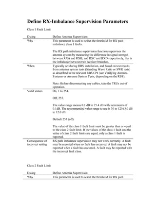
Dialog Define Antenna Supervision
Why This parameter is used to select the threshold for RX path
imbalance class 1 faults.
The RX path imbalance supervision function supervises the
antenna system by measuring the difference in signal strength
between RXA and RXB, and RXC and RXD respectively, that is
the imbalance between two receiver branches.
When Typically set during RBS installation, and based on test results
from antenna system tests (Standing Wave Ratio or SWR tests)
as described in the relevant RBS CPI (see Verifying Antenna
Systems or Antenna System Tests, depending on the RBS).
Note: Before disconnecting any cables, take the TRUs out of
operation.
Valid values On, 1 to 254.
Off, 255.
The value range means 0.1 dB to 25.4 dB with increments of
0.1dB. The recommended value range to use is 30 to 120 (3.0 dB
to 12.0 dB.
Default 255 (off).
The value of the class 1 fault limit must be greater than or equal
to the class 2 fault limit. If the values of the class 1 fault and the
value of class 2 fault limits are equal, only a class 1 fault is
reported.
Consequence of
incorrect setting
RX path imbalance supervision may not work correctly. A fault
may be reported when no fault has occurred. A fault may not be
reported when a fault has occurred. A fault may be reported with
the incorrect fault class.
Class 2 Fault Limit
Dialog Define Antenna Supervision
Why This parameter is used to select the threshold for RX path
2. imbalance class 2 faults.
The RX path imbalance supervision function supervises the
antenna system by measuring the difference in signal strength
between RXA and RXB, and RXC and RXD respectively that is
the imbalance between two receiver branches.
When Typically set during RBS installation, and based on test results
from antenna system tests (Standing Wave Ratio or SWR tests)
as described in the relevant RBS CPI (see Verifying Antenna
Systems or Antenna System Tests, depending on the RBS).
Note: Before disconnecting any cables, take the TRUs out of
operation.
Valid values On, 1 to 254.
Off, 255.
The value range means 0.1 dB to 25.4 dB with increments of
0.1dB. The recommended value range to use is 30 to 120 (3.0 dB
to 12.0 dB.
Default 60 (6dB).
The value of the class 1 fault limit must be greater than or equal
to the value of the class 2 fault limit. If the values of the class 1
fault and class 2 fault limits are equal, only a class 1 fault is
exported.
Consequence of
incorrect setting
RX path imbalance supervision may not work correctly. A fault
may be reported when no fault has occurred. A fault may not be
reported when a fault has occurred. A fault may be reported with
the incorrect fault class.
Supervision Window Time
Dialog Define Antenna Supervision
Why This parameter is used to specify how long measurement samples
are to be part of the RX path imbalance calculation. RX path
imbalance is calculated as the mean imbalance for two receiver
branches during the specified time.
A shorter supervision window time, gives a more rapid fault
indication but is also more sensitive to short RX path imbalance
disturbances.
3. When Typically at RBS installation, or when more rapid and less stable
values, or slower and more stable values of the RX path
imbalance are needed.
Valid values 5 ņ 3000 minutes or, 5 minutes to 50 hours (default: 1440
minutes, or 24 hours).
Consequence of
incorrect setting
RX path imbalance supervision may not work correctly. A fault
may be reported when no fault has occurred. A fault may not be
reported when a fault has occurred. A fault may be reported with
the incorrect fault class.
Minimum Number Of Samples
Dialog Define Antenna Supervision
Why This parameter is used to select the minimum number of
measurement samples that must be present in the supervision
window for any RX path imbalance faults to be reported. This is
to prevent false alarms in cells where there are low traffic
volumes, as one single phone call could be responsible for most
of the samples if there are low number of samples.
When Typically does not need to be changed.
Valid values 1 ņ 65535 (default: 7000).
Consequence of
incorrect setting
RX path imbalance supervision may not work correctly. A fault
may be reported when no fault has occurred. A fault may not be
reported when a fault has occurred. A fault may be reported with
the incorrect fault class.
4. Define Antenna Supervision
The Define Antenna Supervision operation is used to define threshold values for the
supervision of RX antennas.
Execute this command as follows:
1. Select Configuration | Define | Antenna Supervision
2. Edit to appropriate values.
3. Confirm with OK.
Selecting Reset reverts all changes to their previously defined values.
Cancel closes the dialog box without making any changes.
Class1 Alarm is the threshold value (0.1 .. 25.4) in 1/10dB for I1A and I1B faults on
AO TX, defaults to Off.
Class2 Alarm is the threshold value (0.1 .. 25.4) in 1/10dB for I2A and I2B faults on
AO TX, defaults to 6.0dB.
Supervision Window Time is the time (5..3000) in which the average RX path
imbalance is measured in 5 minute intervals, defaults to 1440 (24h).
Minimum Number Of Samples is the minimum number (1..65535) in any given
Window before any alarm may be raised, defaults to 7000 samples.
Note: Class2 Alarm should be less than Class1 Alarm for proper operation.
Note: Supervision Window Time values that are typed manually will be rounded to
the closest 5 minute interval if outside such an interval.
Note: Any value outside the valid range will be converted to the default value.