
Recommandé
Recommandé
Contenu connexe
Tendances
Tendances (20)
Similaire à 2001 DODGE CARAVAN Service Repair Manual
Similaire à 2001 DODGE CARAVAN Service Repair Manual (9)
Plus de jkejdkm
Plus de jkejdkm (13)
Dernier
Dernier (20)
2001 DODGE CARAVAN Service Repair Manual
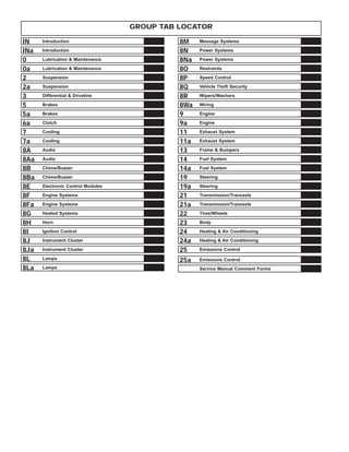
- 1. GROUP TAB LOCATOR IN Introduction INa Introduction 0 Lubrication & Maintenance 0a Lubrication & Maintenance 2 Suspension 2a Suspension 3 Differential & Driveline 5 Brakes 5a Brakes 6a Clutch 7 Cooling 7a Cooling 8A Audio 8Aa Audio 8B Chime/Buzzer 8Ba Chime/Buzzer 8E Electronic Control Modules 8F Engine Systems 8Fa Engine Systems 8G Heated Systems 8H Horn 8I Ignition Control 8J Instrument Cluster 8Ja Instrument Cluster 8L Lamps 8La Lamps 8M Message Systems 8N Power Systems 8Na Power Systems 8O Restraints 8P Speed Control 8Q Vehicle Theft Security 8R Wipers/Washers 8Wa Wiring 9 Engine 9a Engine 11 Exhaust System 11a Exhaust System 13 Frame & Bumpers 14 Fuel System 14a Fuel System 19 Steering 19a Steering 21 Transmission/Transaxle 21a Transmission/Transaxle 22 Tires/Wheels 23 Body 24 Heating & Air Conditioning 24a Heating & Air Conditioning 25 Emissions Control 25a Emissions Control Service Manual Comment Forms
- 2. INTRODUCTION TABLE OF CONTENTS page page VEHICLE SAFETY CERTIFICATION LABEL DESCRIPTION . . . . . . . . . . . . . . . . . . . . . . . . . . . . 1 VEHICLE IDENTIFICATION NUMBER DESCRIPTION . . . . . . . . . . . . . . . . . . . . . . . . . . . . 1 VECI LABEL DESCRIPTION . . . . . . . . . . . . . . . . . . . . . . . . . . . . 3 BODY CODE PLATE DESCRIPTION . . . . . . . . . . . . . . . . . . . . . . . . . . . . 3 INTERNATIONAL SYMBOLS DESCRIPTION . . . . . . . . . . . . . . . . . . . . . . . . . . . . 4 FASTENER IDENTIFICATION DESCRIPTION . . . . . . . . . . . . . . . . . . . . . . . . . . . . 5 FASTENER USAGE DESCRIPTION . . . . . . . . . . . . . . . . . . . . . . . . . . . . 5 METRIC SYSTEM DESCRIPTION . . . . . . . . . . . . . . . . . . . . . . . . . . . . 8 TORQUE REFERENCES DESCRIPTION . . . . . . . . . . . . . . . . . . . . . . . . . . . 10 VEHICLE SAFETY CERTIFICATION LABEL DESCRIPTION A vehicle safety certification label (Fig. 1) is located on the rearward facing of the driver’s door. This label indicates date of manufacture (month and year), Gross Vehicle Weight Rating (GVWR), Gross Axle Weight Rating (GAWR) front, Gross Axle Weight Rating (GAWR) rear and the Vehicle Identification Number (VIN). The Month, Day and Hour (MDH) of manufac- ture is also included. When it is necessary to contact the manufacturer regarding service or warranty, the information on the Vehicle Safety Certification Label would be required. VEHICLE IDENTIFICATION NUMBER DESCRIPTION The Vehicle Identification Number (VIN) can be viewed through the windshield at the upper left cor- ner of the instrument panel, near the left windshield pillar (Fig. 2). The VIN consists of 17 characters in a combination of letters and numbers that provide spe- cific information about the vehicle. Refer to VIN Code Breakdown Chart for decoding information. To protect the consumer from theft and possible fraud the manufacturer is required to include a Check Digit at the ninth position of the Vehicle Identification Number. The check digit is used by the manufacturer and government agencies to verify the authenticity of the vehicle and official documentation. The formula to use the check digit is not released to the general public. Fig. 1 Vehicle Safety Certification Label Fig. 2 Vehicle Identification Number (VIN Plate) 1 - DEFROSTER OUTLET 2 - VIN # 3 - HEATED WINDSHIELD GRID RS INTRODUCTION 1
- 3. VIN CODE BREAKDOWN CHART POSITION INTERPRETATION CODE = DESCRIPTION 1 Country of Origin 1 = Built in the United States by DaimlerChrysler 2 = Built in Canada by DaimlerChrysler Canada Inc. 2 Make B = Dodge C = Chrysler 3 Vehicle Type 4 = Multipurpose Pass. Vehicle Less Side Air Bags 8 = Multipurpose Pass. Vehicle With Side Air Bags 4 Gross Vehicle Weight Rating G = 2268 - 2721 kg. (5001 - 6000 lbs.) 5 Car Line P = Chrysler, Town & Country - FWD P = Dodge, Caravan/Grand Caravan - FWD T = Chrysler, Town & Country - AWD T = Dodge, Grand Caravan - AWD J = Chrysler, Voyager/Grand Voyager - FWD 6 Series 2 = Low Line 4 = High Line 5 = Premium 6 = Sport 7 = Special 7 Body Style 4 = Long Wheel Base 5 = Short Wheel Base 8 Engine B = 2.4 L 4 cyl. MPI 16-VALVE DOHC G = 3.3 L 6 cyl. Ethanol Flexible Fuel MPI R = 3.3 L 6 cyl. Gas MPI L = 3.8 L 6 cyl. Gas MPI 9 Check Digit See explanation in this section. 10 Model Year 1= 2001 11 Assembly Plant B = St. Louis South R = Windsor 12 through 17 Sequence Number A six digit number assigned by assembly plant. 2 INTRODUCTION RS VEHICLE IDENTIFICATION NUMBER (Continued)
- 4. VECI LABEL DESCRIPTION All models have a Vehicle Emission Control Infor- mation (VECI) Label. Chrysler permanently attaches the label in the engine compartment. It cannot be removed without defacing information and destroying the label. The label contains the vehicle’s emission specifica- tions and vacuum hose routings. All hoses must be connected and routed according to the label. BODY CODE PLATE DESCRIPTION The Body Code Plate (Fig. 3) is located in the engine compartment on the radiator closure panel crossmember. There are seven lines of information on the body code plate. Lines 4, 5, 6, and 7 are not used to define service information. Information reads from left to right, starting with line 3 in the center of the plate to line 1 at the bottom of the plate. BODY CODE PLATE – LINE 3 DIGITS 1 THROUGH 12 Vehicle Order Number DIGITS 13 THROUGH 17 Open space DIGITS 18 AND 19 Vehicle Shell Line • NS DIGIT 20 Carline FWD • H = Plymouth • K = Dodge • Y = Chrysler AWD • C = Chrysler • D = Dodge • P = Plymouth DIGIT 21 Price Class • H = Highline • L = Lowline • P = Premium • S = Luxury • X = Premium DIGITS 22 AND 23 Body Type • 52 = Short Wheel Base • 53 = Long Wheel Base BODY CODE PLATE LINE 2 DIGITS 1, 2 AND 3 Paint procedure DIGIT 4 Open Space DIGITS 5 THROUGH 7 Primary paint Refer to Group 23, Body for color codes. DIGIT 8 AND 9 Open Space DIGITS 10 THROUGH 12 Secondary Paint Fig. 3 Body Code Plate 1 - PRIMARY PAINT 2 - SECONDARY PAINT 3 - VINYL ROOF 4 - VEHICLE ORDER NUMBER 5 - CAR LINE SHELL 6 - PAINT PROCEDURE 7 - ENGINE 8 - TRIM 9 - TRANSMISSION 10 - MARKET 11 - VIN RS INTRODUCTION 3
- 5. DIGIT 13 AND 14 Open Space DIGITS 15 THROUGH 18 Interior Trim Code DIGIT 19 Open Space DIGITS 20, 21, AND 22 Engine Code • EDZ = 2.4 L 4 cyl. DOHC Gasoline • EFA = 3.0 L 6 cyl. Gasoline • EGA = 3.3 L 6 cyl. Gasoline • EGH = 3.8 L 6 cyl. Gasoline • EGM = 3.3 L 6 cyl. Ethanol Flexible Fuel DIGIT 23 Open Space BODY CODE PLATE LINE 1 DIGITS 1, 2, AND 3 Transaxle Codes • DGB = 41TH 4-speed Automatic Transaxle • DGL = 41TE 4-speed Electronic Automatic Tran- saxle • DGM = 31TH 3-speed Automatic Transaxle DIGIT 4 Open Space DIGIT 5 Market Code • C = Canada • B = International • M = Mexico • U = United States DIGIT 6 Open Space DIGITS 7 THROUGH 23 Vehicle Identification Number • Refer to Vehicle Identification Number (VIN) paragraph for proper breakdown of VIN code. IF TWO BODY CODE PLATES ARE REQUIRED The last code shown on either plate will be fol- lowed by END. When two plates are required, the last code space on the first plate will indicate (CTD) When a second plate is required, the first four spaces of each line will not be used due to overlap of the plates. INTERNATIONAL SYMBOLS DESCRIPTION The graphic symbols illustrated in the following International Control and Display Symbols Chart are used to identify various instrument controls. The symbols correspond to the controls and displays that are located on the instrument panel. 4 INTRODUCTION RS BODY CODE PLATE (Continued)
- 6. FASTENER IDENTIFICATION DESCRIPTION The SAE bolt strength grades range from grade 2 to grade 8. The higher the grade number, the greater the bolt strength. Identification is determined by the line marks on the top of each bolt head. The actual bolt strength grade corresponds to the number of line marks plus 2. The most commonly used metric bolt strength classes are 9.8 and 10.9. The metric strength class identification number is imprinted on the head of the bolt. The higher the class number, the greater the bolt strength. Some metric nuts are imprinted with a single-digit strength class on the nut face. Refer to the Fastener Identification and Fastener Strength Charts. FASTENER USAGE DESCRIPTION - FASTENER USAGE WARNING: USE OF AN INCORRECT FASTENER MAY RESULT IN COMPONENT DAMAGE OR PER- SONAL INJURY. Figure art, specifications and torque references in this Service Manual are identified in metric and SAE format. During any maintenance or repair procedures, it is important to salvage all fasteners (nuts, bolts, etc.) for reassembly. If the fastener is not salvageable, a fastener of equivalent specification must be used. International Symbols 1 High Beam 13 Rear Window Washer 2 Fog Lamps 14 Fuel 3 Headlamp, Parking Lamps, Panel Lamps 15 Engine Coolant Temperature 4 Turn Warning 16 Battery Charging Condition 5 Hazard Warning 17 Engine Oil 6 Windshield Washer 18 Seat Belt 7 Windshield Wiper 19 Brake Failure 8 Windshield Wiper and Washer 20 Parking Brake 9 Windscreen Demisting and Defrosting 21 Front Hood 10 Ventilating Fan 22 Rear hood (Decklid) 11 Rear Window Defogger 23 Horn 12 Rear Window Wiper 24 Lighter RS INTRODUCTION 5 INTERNATIONAL SYMBOLS (Continued)
- 7. FASTENER IDENTIFICATION 6 INTRODUCTION RS FASTENER USAGE (Continued)
- 8. FASTENER STRENGTH RS INTRODUCTION 7 FASTENER USAGE (Continued)
- 9. DESCRIPTION - THREADED HOLE REPAIR Most stripped threaded holes can be repaired using a Helicoil. Follow the vehicle or Helicoil recommen- dations for application and repair procedures. METRIC SYSTEM DESCRIPTION - METRIC SYSTEM The metric system is based on quantities of one, ten, one hundred, one thousand and one million . The following chart will assist in converting metric units to equivalent English and SAE units, or vise versa. CONVERSION FORMULAS AND EQUIVALENT VALUES MULTIPLY BY TO GET MULTIPLY BY TO GET in-lbs x 0.11298 = Newton Meters (N·m) N·m x 8.851 = in-lbs ft-lbs x 1.3558 = Newton Meters (N·m) N·m x 0.7376 = ft-lbs Inches Hg (60° F) x 3.377 = Kilopascals (kPa) kPa x 0.2961 = Inches Hg psi x 6.895 = Kilopascals (kPa) kPa x 0.145 = psi Inches x 25.4 = Millimeters (mm) mm x 0.03937 = Inches Feet x 0.3048 = Meters (M) M x 3.281 = Feet Yards x 0.9144 = Meters M x 1.0936 = Yards mph x 1.6093 = Kilometers/Hr. (Km/h) Km/h x 0.6214 = mph Feet/Sec x 0.3048 = Meters/Sec (M/S) M/S x 3.281 = Feet/Sec mph x 0.4470 = Meters/Sec (M/S) M/S x 2.237 = mph Kilometers/ Hr. (Km/h) x 0.27778 = Meters/Sec (M/S) M/S x 3.600 Kilometers/Hr. (Km/h) COMMON METRIC EQUIVALENTS 1 inch = 25 Millimeters 1 Cubic Inch = 16 Cubic Centimeters 1 Foot = 0.3 Meter 1 Cubic Foot = 0.03 Cubic Meter 1 Yard = 0.9 Meter 1 Cubic Yard = 0.8 Cubic Meter 1 Mile = 1.6 Kilometers Refer to the Metric Conversion Chart to convert torque values listed in metric Newton- meters (N·m). Also, use the chart to convert between millimeters (mm) and inches (in.) 8 INTRODUCTION RS FASTENER USAGE (Continued)
- 10. METRIC CONVERSION CHART RS INTRODUCTION 9 METRIC SYSTEM (Continued)
- 11. TORQUE REFERENCES DESCRIPTION Individual Torque Charts appear within many or the Groups. Refer to the Standard Torque Specifica- tions Chart for torque references not listed in the individual torque charts. TORQUE SPECIFICATIONS 10 INTRODUCTION RS
- 12. INTRODUCTION TABLE OF CONTENTS page page BODY CODE PLATE DESCRIPTION . . . . . . . . . . . . . . . . . . . . . . . . . . . . 1 FASTENER IDENTIFICATION DESCRIPTION . . . . . . . . . . . . . . . . . . . . . . . . . . . . 2 FASTENER USAGE DESCRIPTION . . . . . . . . . . . . . . . . . . . . . . . . . . . . 5 THREADED HOLE REPAIR DESCRIPTION . . . . . . . . . . . . . . . . . . . . . . . . . . . . 5 INTERNATIONAL VEHICLE CONTROL & DISPLAY SYMBOLS DESCRIPTION . . . . . . . . . . . . . . . . . . . . . . . . . . . . 5 METRIC SYSTEM DESCRIPTION . . . . . . . . . . . . . . . . . . . . . . . . . . . . 6 TORQUE REFERENCES DESCRIPTION . . . . . . . . . . . . . . . . . . . . . . . . . . . . 8 VEHICLE IDENTIFICATION NUMBER DESCRIPTION . . . . . . . . . . . . . . . . . . . . . . . . . . . . 9 VEHICLE SAFETY CERTIFICATION LABEL DESCRIPTION . . . . . . . . . . . . . . . . . . . . . . . . . . . 10 E-MARK LABEL DESCRIPTION . . . . . . . . . . . . . . . . . . . . . . . . . . . 10 VECI LABEL DESCRIPTION . . . . . . . . . . . . . . . . . . . . . . . . . . . 10 MANUFACTURE PLATE DESCRIPTION . . . . . . . . . . . . . . . . . . . . . . . . . . . 10 BODY CODE PLATE DESCRIPTION The Body Code Plate (Fig. 1) is located in the engine compartment on the radiator closure panel crossmember. There are seven lines of information on the body code plate. Lines 4, 5, 6, and 7 are not used to define service information. Information reads from left to right, starting with line 3 in the center of the plate to line 1 at the bottom of the plate. BODY CODE PLATE – LINE 3 DIGITS 1 THROUGH 12 Vehicle Order Number DIGITS 13 THROUGH 17 Open space DIGITS 18 AND 19 Vehicle Shell Line • RG DIGIT 20 Carline FWD • Y = Chrysler AWD • C = Chrysler Fig. 1 BODY CODE PLATE 1 - PRIMARY PAINT 2 - SECONDARY PAINT 3 - VINYL ROOF 4 - VEHICLE ORDER NUMBER 5 - CAR LINE SHELL 6 - PAINT PROCEDURE 7 - ENGINE 8 - TRIM 9 - TRANSMISSION 10 - MARKET 11 - VIN RG INTRODUCTION 1a
- 13. DIGIT 21 Price Class • H = Highline • L = Lowline • P = Premium • S = Luxury • X = Premium DIGITS 22 AND 23 Body Type • 52 = Short Wheel Base • 53 = Long Wheel Base BODY CODE PLATE LINE 2 DIGITS 1, 2 AND 3 Paint procedure DIGIT 4 Open Space DIGITS 5 THROUGH 7 Primary paint(Refer to 23 - BODY/PAINT - SPEC- IFICATIONS). DIGIT 8 AND 9 Open Space DIGITS 10 THROUGH 12 Secondary Paint DIGIT 13 AND 14 Open Space DIGITS 15 THROUGH 18 Interior Trim Code DIGIT 19 Open Space DIGITS 20, 21, AND 22 Engine Code • ENC = 2.5 L 4 cyl. Turbo Diesel DIGIT 23 Open Space BODY CODE PLATE LINE 1 DIGITS 1, 2, AND 3 Transaxle Codes • DGB = 41TH 4-speed Automatic Transaxle • DGL = 41TE 4-speed Electronic Automatic Transaxle • DGM = 31TH 3-speed Automatic Transaxle DIGIT 4 Open Space DIGIT 5 Market Code • C = Canada • B = International • M = Mexico • U = United States DIGIT 6 Open Space DIGITS 7 THROUGH 23 Vehicle Identification Number • Refer to Vehicle Identification Number (VIN) paragraph for proper breakdown of VIN code. IF TWO BODY CODE PLATES ARE REQUIRED The last code shown on either plate will be fol- lowed by END. When two plates are required, the last code space on the first plate will indicate (CTD) When a second plate is required, the first four spaces of each line will not be used due to overlap of the plates. FASTENER IDENTIFICATION DESCRIPTION The SAE bolt strength grades range from grade 2 to grade 8. The higher the grade number, the greater the bolt strength. Identification is determined by the line marks on the top of each bolt head. The actual bolt strength grade corresponds to the number of line marks plus 2. The most commonly used metric bolt strength classes are 9.8 and 10.9. The metric strength class identification number is imprinted on the head of the bolt. The higher the class number, the greater the bolt strength. Some metric nuts are imprinted with a single-digit strength class on the nut face. Refer to the Fastener Identification and Fastener Strength Charts (Fig. 2) and (Fig. 3). 2a INTRODUCTION RG BODY CODE PLATE (Continued)
- 14. Fig. 2 FASTENER IDENTIFICATION RG INTRODUCTION 3a FASTENER IDENTIFICATION (Continued)
- 15. Fig. 3 FASTENER STRENGTH 4a INTRODUCTION RG FASTENER IDENTIFICATION (Continued)
- 16. FASTENER USAGE DESCRIPTION WARNING: USE OF AN INCORRECT FASTENER MAY RESULT IN COMPONENT DAMAGE OR PER- SONAL INJURY. Figure art, specifications and torque references in this Service Manual are identified in metric and SAE format. During any maintenance or repair procedures, it is important to salvage all fasteners (nuts, bolts, etc.) for reassembly. If the fastener is not salvageable, a fastener of equivalent specification must be used. THREADED HOLE REPAIR DESCRIPTION Most stripped threaded holes can be repaired using a Helicoil. Follow the vehicle or Helicoil recommen- dations for application and repair procedures. INTERNATIONAL VEHICLE CONTROL & DISPLAY SYMBOLS DESCRIPTION The graphic symbols illustrated in the following International Control and Display Symbols Chart (Fig. 4) are used to identify various instrument con- trols. The symbols correspond to the controls and dis- plays that are located on the instrument panel. Fig. 4 INTERNATIONAL CONTROL AND DISPLAY SYMBOLS 1 High Beam 13 Rear Window Washer 2 Fog Lamps 14 Fuel 3 Headlamp, Parking Lamps, Panel Lamps 15 Engine Coolant Temperature 4 Turn Warning 16 Battery Charging Condition 5 Hazard Warning 17 Engine Oil 6 Windshield Washer 18 Seat Belt 7 Windshield Wiper 19 Brake Failure 8 Windshield Wiper and Washer 20 Parking Brake 9 Windscreen Demisting and Defrosting 21 Front Hood 10 Ventilating Fan 22 Rear hood (Decklid) 11 Rear Window Defogger 23 Horn 12 Rear Window Wiper 24 Lighter RG INTRODUCTION 5a
- 17. METRIC SYSTEM DESCRIPTION The metric system is based on quantities of one, ten, one hundred, one thousand and one million. The following chart will assist in converting metric units to equivalent English and SAE units, or vise versa. CONVERSION FORMULAS AND EQUIVALENT VALUES MULTIPLY BY TO GET MULTIPLY BY TO GET in-lbs x 0.11298 = Newton Meters (N·m) N·m x 8.851 = in-lbs ft-lbs x 1.3558 = Newton Meters (N·m) N·m x 0.7376 = ft-lbs Inches Hg (60° F) x 3.377 = Kilopascals (kPa) kPa x 0.2961 = Inches Hg psi x 6.895 = Kilopascals (kPa) kPa x 0.145 = psi Inches x 25.4 = Millimeters (mm) mm x 0.03937 = Inches Feet x 0.3048 = Meters (M) M x 3.281 = Feet Yards x 0.9144 = Meters M x 1.0936 = Yards mph x 1.6093 = Kilometers/Hr. (Km/h) Km/h x 0.6214 = mph Feet/Sec x 0.3048 = Meters/Sec (M/S) M/S x 3.281 = Feet/Sec mph x 0.4470 = Meters/Sec (M/S) M/S x 2.237 = mph Kilometers/Hr. (Km/h) x 0.27778 = Meters/Sec (M/S) M/S x 3.600 Kilometers/Hr. (Km/h) COMMON METRIC EQUIVALENTS 1 inch = 25 Millimeters 1 Cubic Inch = 16 Cubic Centimeters 1 Foot = 0.3 Meter 1 Cubic Foot = 0.03 Cubic Meter 1 Yard = 0.9 Meter 1 Cubic Yard = 0.8 Cubic Meter 1 Mile = 1.6 Kilometers Refer to the Metric Conversion Chart to convert torque values listed in metric Newton- meters (N·m). Also, use the chart to convert between millimeters (mm) and inches (in.) 6a INTRODUCTION RG
- 18. METRIC CONVERSION CHART RG INTRODUCTION 7a METRIC SYSTEM (Continued)
- 19. TORQUE REFERENCES DESCRIPTION Individual Torque Charts appear within many or the Groups. Refer to the Standard Torque Specifica- tions Chart for torque references not listed in the individual torque charts. TORQUE SPECIFICATIONS 8a INTRODUCTION RG
- 20. VEHICLE IDENTIFICATION NUMBER DESCRIPTION The Vehicle Identification Number (VIN) can be viewed through the windshield at the upper left cor- ner of the instrument panel, near the left windshield pillar (Fig. 5). The VIN consists of 17 characters in a combination of letters and numbers that provide spe- cific information about the vehicle. Refer to VIN Code Breakdown Chart for decoding information. To protect the consumer from theft and possible fraud the manufacturer is required to include a Check Digit at the ninth position of the Vehicle Iden- tification Number. The check digit is used by the manufacturer and government agencies to verify the authenticity of the vehicle and official documenta- tion. The formula to use the check digit is not released to the general public. VIN CODE BREAKDOWN CHART POSITION INTERPRETATION CODE = DESCRIPTION 1 Country of Origin 1 = Built in the Graz Austria by DaimlerChrysler 2 Make C = Chrysler 3 Vehicle Type 4 = Multipurpose Pass. Vehicle Less Side Air Bags 8 = Multipurpose Pass. Vehicle With Side Air Bags 4 Gross Vehicle Weight Rating G = 2268 - 2721 kg. (5001 - 6000 lbs.) 5 Car Line Y = Voyager/Grand Voyager - FWD Left Hand Drive C = Voyager/Grand Voyager - AWD Left Hand Drive H = Voyager/Grand Voyager - FWD Right Hand Drive K = Voyager/Grand Voyager - AWD Right Hand Drive I = Caravan FWD 6 Series 2 = Low Line 4 = High Line 5 = Premium 6 = Sport 7 = Special 7 Body Style 4 = Long Wheel Base 5 = Short Wheel Base 8 Engine B = 2.4 L 4 cyl. MPI 16 - VALVE DOHC R = 3.3 L 6 cyl. Gasoline MPI M = 2.5 L 4 cyl. Turbo Diesel 9 Check Digit See explanation in this section. 10 Model Year 1= 2001 11 Assembly Plant U = Graz Austria 12 through 17 Sequence Number A six digit number assigned by assembly plant. Fig. 5 Vehicle Identification Number (VIN Plate) 1 - DEFROSTER OUTLET 2 - VIN # 3 - HEATED WINDSHIELD GRID RG INTRODUCTION 9a
- 21. VEHICLE SAFETY CERTIFICATION LABEL DESCRIPTION A vehicle safety certification label (Fig. 6) is located on the rearward facing of the driver’s door. This label indicates date of manufacture (month and year), Gross Vehicle Weight Rating (GVWR), Gross Axle Weight Rating (GAWR) front, Gross Axle Weight Rat- ing (GAWR) rear and the Vehicle Identification Num- ber (VIN). The Month, Day and Hour (MDH) of manufacture is also included. When it is necessary to contact the manufacturer regarding service or warranty, the information on the Vehicle Safety Certification Label would be required. E-MARK LABEL DESCRIPTION An E-mark Label (Fig. 7) is located on the rear shut face of the driver’s door. The label contains the following information: • Date of Manufacture • Month-Day-Hour (MDH) • Vehicle Identification Number (VIN) • Country Codes • Regulation Number • Regulation Amendment Number • Approval Number VECI LABEL DESCRIPTION All models have a Vehicle Emission Control Infor- mation (VECI) Label. Chrysler permanently attaches the label in the engine compartment. It cannot be removed without defacing information and destroying the label. The label contains the vehicle’s emission specifica- tions and vacuum hose routings. All hoses must be connected and routed according to the label. MANUFACTURE PLATE DESCRIPTION The Manufacturer Plate (Fig. 8) is located in the engine compartment on the passenger side strut tower. The plate contains five lines of information: • Vehicle Identification Number (VIN) • Gross Vehicle Mass (GVM) • Gross Train Mass (GTM) • Gross Front Axle Rating (GFAR) • Gross Rear Axle Rating (GRAR) Fig. 6 Vehicle Safety Certification Label Fig. 7 E-Mark Label 1 - Country Code 2 - Regulation Number 3 - Approval Number 4 - Amendment Number Fig. 8 Manufacturer Plate 10a INTRODUCTION RG
- 22. LUBRICATION & MAINTENANCE TABLE OF CONTENTS page page LUBRICATION & MAINTENANCE SPECIFICATIONS . . . . . . . . . . . . . . . . . . . . . . . . . 1 INTERNATIONAL SYMBOLS DESCRIPTION . . . . . . . . . . . . . . . . . . . . . . . . . . . . 1 PARTS & LUBRICANT RECOMMENDATION STANDARD PROCEDURE . . . . . . . . . . . . . . . . . . . 2 LUBRICANT CLASSIFICATIONS. . . . . . . . . . . . . 2 PARTS AND LUBRICANT RECOMMENDATIONS . . . . . . . . . . . . . . . . . . . . 2 FLUID TYPES DESCRIPTION . . . . . . . . . . . . . . . . . . . . . . . . . . . . 3 OPERATION . . . . . . . . . . . . . . . . . . . . . . . . . . . . . 7 FLUID FILL/CHECK LOCATIONS DESCRIPTION . . . . . . . . . . . . . . . . . . . . . . . . . . . . 7 MAINTENANCE SCHEDULES DESCRIPTION . . . . . . . . . . . . . . . . . . . . . . . . . . . . 7 HOISTING STANDARD PROCEDURE . . . . . . . . . . . . . . . . . . 16 HOISTING . . . . . . . . . . . . . . . . . . . . . . . . . . . . 16 JUMP STARTING STANDARD PROCEDURE . . . . . . . . . . . . . . . . . . 16 JUMP STARTING . . . . . . . . . . . . . . . . . . . . . . . 16 TOWING STANDARD PROCEDURE . . . . . . . . . . . . . . . . . . 17 TOWING RECOMMENDATIONS . . . . . . . . . . . . 17 LUBRICATION & MAINTENANCE SPECIFICATIONS SPECIFICATIONS - FLUID CAPACITIES DESCRIPTION SPECIFICATION Fuel Tank 75 L (20 gal.) Engine Oil* - 2.4L 4.7 L (5.0 qts.) Engine Oil* - 3.3/3.8L 4.0 L (4.5 qts.) Cooling System** - 2.4L 10.7 L (11.4 qts.) Cooling System** - 3.3/3.8L without Rear Heater 12.6 L (13.4 qts.) Cooling System** - 3.3/3.8L with Rear Heater 15.4 L (16.3 qts.) Automatic Transaxle - Service Fill 3.8 L (4.0 qts.) Automatic Transaxle - 31TH Overhaul Fill 8.6 L (9.1 qts.) Automatic Transaxle - 41TE Overhaul Fill 9.2 L (9.7 qts.) AWD Power Transfer Unit 1.15 L (2.4 pts.) Power Steering 1.2 L (2.5 pts.) AWD Bi-directional Overrunning Clutch 0.575 L (1.22 pts.) DESCRIPTION SPECIFICATION AWD Rear Carrier 0.7 L (1.48 pts.) *(includes oil filter) **(includes heater and recovery/reserve bottle) INTERNATIONAL SYMBOLS DESCRIPTION DaimlerChrysler Corporation uses international symbols to identify engine compartment lubricant and fluid check and fill locations (Fig. 1). Fig. 1 International Symbols RS LUBRICATION & MAINTENANCE 0 - 1
- 23. PARTS & LUBRICANT RECOMMENDATION STANDARD PROCEDURE - Classification of Lubricants Only lubricants that bear designations defined by the following organization should be used to service a DaimlerChrysler vehicle. • Society of Automotive Engineers (SAE) • American Petroleum Institute (API) (Fig. 2) • National Lubricating Grease Institute (NLGI) (Fig. 3) ENGINE OIL SAE VISCOSITY RATING INDICATES ENGINE OIL VISCOSITY An SAE viscosity grade is used to specify the vis- cosity of engine oil. Engine oils also have multiple viscosities. These are specified with a dual SAE vis- cosity grade which indicates the cold-to-hot tempera- ture viscosity range. • SAE 30 = single grade engine oil. • SAE 10W-30 = multiple grade engine oil.Daim- lerChrysler only recommends multiple grade engine oils. API QUALITY CLASSIFICATION This symbol (Fig. 2) on the front of an oil container means that the oil has been certified by the Ameri- can Petroleum Institute (API) to meet all the lubri- cation requirements specified by DaimlerChrysler. Refer to Group 9, Engine for gasoline engine oil specification. FLEXIBLE FUEL ENGINE OIL – 3.3L ENGINE Engine Oil Selection for Operating on E-85 Fuel If vehicle operates on E-85 fuel either full or part-time, use only Mopar Flexible Fuel SAE 5W-30 engine oil or an equivalent that meets DaimlerChrysler Standard MS-9214. Equivalent com- mercial Flexible Fuel engine oils may be labeled as Multi-Fuel, Variable Fuel, Flexible Fuel, etc. These engine oils are preferred for use in Flexible Fuel engines. CAUTION: If Flexible Fuel engine oil is not used when using E-85 fuel, engine wear or damage may result. GEAR LUBRICANTS SAE ratings also apply to multiple grade gear lubricants. In addition, API classification defines the lubricants usage. LUBRICANTS AND GREASES Lubricating grease is rated for quality and usage by the NLGI. All approved products have the NLGI symbol (Fig. 3)on the label. At the bottom NLGI sym- bol is the usage and quality identification letters. Wheel bearing lubricant is identified by the letter “G”. Chassis lubricant is identified by the latter “L”. The letter following the usage letter indicates the quality of the lubricant. The following symbols indi- cate the highest quality. STANDARD PROCEDURE - PARTS AND LUBRICANT RECOMMENDATIONS When service is required, DaimlerChrysler Motor Corporation recommends that only Mopar brand parts, lubricants and chemicals be used. Mopar pro- vides the best engineered products for servicing DaimlerChrysler Corporation vehicles. ENGINE COOLANT The green coolant MUST NOT BE MIXED with the orange or magenta coolants. When replacing cool- ant the complete system flush must be performed before using the replacement coolant. (Refer to LUBRICATION & MAINTENANCE/FLUID TYPES - DESCRIPTION) Fig. 2 API Symbol Fig. 3 NLGI Symbol 1 - WHEEL BEARINGS 2 - CHASSIS LUBRICATION 3 - CHASSIS AND WHEEL BEARINGS 0 - 2 LUBRICATION & MAINTENANCE RS
- 24. FLUID TYPES DESCRIPTION E-85 GENERAL INFORMATION The information in this section is for Flexible Fuel Vehicles (FFV) only. These vehicles can be identified by the unique Fuel Filler Door Label that states Ethanol (E-85) or Unleaded Gasoline Only. This sec- tion only covers those subjects that are unique to these vehicles. Please refer to the other sections of this manual for information on features that are common between Flexible Fuel and gasoline only powered vehicles. ETHANOL FUEL (E-85) E-85 is a mixture of approximately 85% fuel etha- nol and 15% unleaded gasoline. WARNING: Ethanol vapors are extremely flammable and could cause serious personal injury. Never have any smoking materials lit in or near the vehi- cle when removing the fuel filler tube cap (gas cap) or filling the tank. Do not use E-85 as a cleaning agent and never use it near an open flame. FUEL REQUIREMENTS The vehicle will operate on both unleaded gasoline with an octane rating of 87, or E-85 fuel, or any mix- ture of these two. For best results, a refueling pattern that alternates between E-85 and unleaded gasoline should be avoided. When you do switch fuels, it is recom- mended that • you do not switch when the fuel gauge indicates less than 1/4 full • you do not add less than 5 gallons when refuel- ing • you operate the vehicle immediately after refuel- ing for a period of at least 5 minutes Observing these precautions will avoid possible hard starting and/or significant deterioration in driveability during warm up. FFV STARTING The characteristics of E-85 fuel make it unsuitable for use when ambient temperatures fall below 0°F. In the range of 0°F to 32°F, you may experience an increase in the time it takes for your engine to start, and a deterioration in driveability (sags and/or hesi- tations) until the engine is fully warmed up. CRUISING RANGE Because E-85 fuel contains less energy per gallon than gasoline, you will experience an increase in fuel consumption. You can expect your MPG and your driving range to decrease by about 30% compared to gasoline operation. ENGINE OIL WARNING: NEW OR USED ENGINE OIL CAN BE IRRITATING TO THE SKIN. AVOID PROLONGED OR REPEATED SKIN CONTACT WITH ENGINE OIL. CONTAMINANTS IN USED ENGINE OIL, CAUSED BY INTERNAL COMBUSTION, CAN BE HAZARDOUS TO YOUR HEALTH. THOROUGHLY WASH EXPOSED SKIN WITH SOAP AND WATER. DO NOT WASH SKIN WITH GASOLINE, DIESEL FUEL, THINNER, OR SOLVENTS, HEALTH PROBLEMS CAN RESULT. DO NOT POLLUTE, DISPOSE OF USED ENGINE OIL PROPERLY. CONTACT YOUR DEALER OR GOVERN- MENT AGENCY FOR LOCATION OF COLLECTION CENTER IN YOUR AREA. API SERVICE GRADE CERTIFIED Use an engine oil that is API Service Grade Certi- fied. MOPAR provides engine oils that conform to this service grade. SAE VISCOSITY An SAE viscosity grade is used to specify the vis- cosity of engine oil. Use only engine oils with multi- ple viscosities such as 5W-30 or 10W-30. These are specified with a dual SAE viscosity grade which indi- cates the cold-to-hot temperature viscosity range. Select an engine oil that is best suited to your par- ticular temperature range and variation (Fig. 4). ENERGY CONSERVING OIL An Energy Conserving type oil is recommended for gasoline engines. The designation of ENERGY CON- SERVING is located on the label of an engine oil con- tainer. Fig. 4 Temperature/Engine Oil Viscosity RS LUBRICATION & MAINTENANCE 0 - 3
- 25. CONTAINER IDENTIFICATION Standard engine oil identification notations have been adopted to aid in the proper selection of engine oil. The identifying notations are located on the label of engine oil plastic bottles and the top of engine oil cans (Fig. 5). This symbol on the front of an oil container means that the oil has been certified by the American Petro- leum Institute (API) to meet all the lubrication requirements specified by DaimlerChrysler. FLEXIBLE FUEL ENGINE OIL - 3.3L Engine Oil Selection for Operating on E-85 Fuel If vehicle operates on E-85 fuel either full or part- time, use only Mopar Flexible Fuel 5W-30 engine oil or an equivalent that meets DaimlerChrysler Stan- dard MS-9214. Equivalent commercial Flexible Fuel engine oils may be labeled as Multi-Fuel, Variable Fuel, Flexible Fuel, etc. These engine oils may be satisfactory if they meet the DaimlerChrysler Stan- dard. SAE 5W-30 engine oil is preferred for use in Flex- ible Fuel engines. CAUTION: If Flexible Fuel engine oil is not used when using E-85 fuel, engine wear or damage may result. DESCRIPTION - AUTOMATIC TRANSMISSION FLUID NOTE: Refer to the maintenance schedules for the recommended maintenance (fluid/filter change) intervals for this transaxle. NOTE: For fluid level checking procedures, (Refer to 21 - TRANSMISSION/TRANSAXLE/AUTOMATIC - 31TH/FLUID - STANDARD PROCEDURE) (Refer to 21 - TRANSMISSION/TRANSAXLE/AUTOMATIC - 41TE/ FLUID - STANDARD PROCEDURE) NOTE: The 41TE transaxle has a common transmis- sion and differential sump. Filling the transaxle accommodates the differential as well. TRANSMISSION FLUID Mopar ATF+4 (Automatic Transmission Fluid- Type 9602) is required in this transaxle. Substitute fluids can induce torque converter clutch shudder. Mopar ATF+4 (Automatic Transmission Fluid- Type 9602) when new is red in color. The ATF is dyed red so it can be identified from other fluids used in the vehicle such as engine oil or antifreeze. The red color is not permanent and is not an indicator of fluid condition. As the vehicle is driven, the ATF will begin to look darker in color and may eventually become brown. This is normal. A dark brown/black fluid accompanied with a burnt odor and/or deterioration in shift quality may indicate fluid deterioration or transmission component failure. FLUID ADDITIVES DaimlerChrysler strongly recommends against the addition of any fluids to the transmission, other than those automatic transmission fluids listed above. Exceptions to this policy are the use of special dyes to aid in detecting fluid leaks. Various “special” additives and supplements exist that claim to improve shift feel and/or quality. These additives and others also claim to improve converter clutch operation and inhibit overheating, oxidation, varnish, and sludge. These claims have not been sup- ported to the satisfaction of DaimlerChrysler and these additives must not be used. The use of trans- mission “sealers” should also be avoided, since they may adversely affect the integrity of transmission seals. DESCRIPTION - FUEL REQUIREMENTS Your engine is designed to meet all emissions reg- ulations and provide excellent fuel economy and per- formance when using high quality unleaded gasoline having an octane rating of 87. The use of premium gasoline is not recommended. The use of premium gasoline will provide no benefit over high quality reg- ular gasoline, and in some circumstances may result in poorer performance. Light spark knock at low engine speeds is not harmful to your engine. However, continued heavy spark knock at high speeds can cause damage and immediate service is required. Engine damage result- ing from operation with a heavy spark knock may not be covered by the new vehicle warranty. Poor quality gasoline can cause problems such as hard starting, stalling and hesitations. If you experi- ence these symptoms, try another brand of gasoline before considering service for the vehicle. Fig. 5 Engine Oil Container Standard Notations 0 - 4 LUBRICATION & MAINTENANCE RS FLUID TYPES (Continued)
- 26. Over 40 auto manufacturers world-wide have issued and endorsed consistent gasoline specifications (the Worldwide Fuel Charter, WWFC) to define fuel properties necessary to deliver enhanced emissions, performance and durability for your vehicle. We rec- ommend the use of gasolines that meet the WWFC specifications if they are available. REFORMULATED GASOLINE Many areas of the country require the use of cleaner burning gasoline referred to as “reformulat- ed” gasoline. Reformulated gasoline contain oxygen- ates, and are specifically blended to reduce vehicle emissions and improve air quality. We strongly supports the use of reformulated gas- oline. Properly blended reformulated gasoline will provide excellent performance and durability for the engine and fuel system components. GASOLINE/OXYGENATE BLENDS Some fuel suppliers blend unleaded gasoline with oxygenates such as 10% ethanol, MTBE, and ETBE. Oxygenates are required in some areas of the country during the winter months to reduce carbon monoxide emissions. Fuels blended with these oxygenates may be used in your vehicle. CAUTION: DO NOT use gasoline containing METH- ANOL. Gasoline containing methanol may damage critical fuel system components. MMT IN GASOLINE MMT is a manganese-containing metallic additive that is blended into some gasoline to increase octane. Gasoline blended with MMT provide no performance advantage beyond gasoline of the same octane num- ber without MMT. Gasoline blended with MMT reduce spark plug life and reduce emission system performance in some vehicles. We recommend that gasolines free of MMT be used in your vehicle. The MMT content of gasoline may not be indicated on the gasoline pump; therefore, you should ask your gaso- line retailer whether or not his/her gasoline contains MMT. It is even more important to look for gasoline with- out MMT in Canada because MMT can be used at levels higher than allowed in the United States. MMT is prohibited in Federal and California refor- mulated gasoline. SULFUR IN GASOLINE If you live in the northeast United States, your vehicle may have been designed to meet California low emission standards with Cleaner-Burning Cali- fornia reformulated gasoline with low sulfur. If such fuels are not available in states adopting California emission standards, your vehicles will operate satis- factorily on fuels meeting federal specifications, but emission control system performance may be adversely affected. Gasoline sold outside of California is permitted to have higher sulfur levels which may affect the performance of the vehicle’s catalytic con- verter. This may cause the Malfunction Indicator Lamp (MIL), Check Engine or Service Engine Soon light to illuminate. We recommend that you try a dif- ferent brand of unleaded gasoline having lower sulfur to determine if the problem is fuel related prior to returning your vehicle to an authorized dealer for service. CAUTION: If the Malfunction Indicator Lamp (MIL), Check Engine or Service Engine Soon light is flash- ing, immediate service is required; see on-board diagnostics system section. MATERIALS ADDED TO FUEL All gasoline sold in the United States and Canada are required to contain effective detergent additives. Use of additional detergents or other additives is not needed under normal conditions. FUEL SYSTEM CAUTIONS CAUTION: Follow these guidelines to maintain your vehicle’s performance: • The use of leaded gas is prohibited by Federal law. Using leaded gasoline can impair engine perfor- mance, damage the emission control system, and could result in loss of warranty coverage. • An out-of-tune engine, or certain fuel or ignition malfunctions, can cause the catalytic converter to overheat. If you notice a pungent burning odor or some light smoke, your engine may be out of tune or malfunctioning and may require immediate service. Contact your dealer for service assistance. • When pulling a heavy load or driving a fully loaded vehicle when the humidity is low and the tem- perature is high, use a premium unleaded fuel to help prevent spark knock. If spark knock persists, lighten the load, or engine piston damage may result. • The use of fuel additives which are now being sold as octane enhancers is not recommended. Most of these products contain high concentrations of methanol. Fuel system damage or vehicle perfor- mance problems resulting from the use of such fuels or additives is not the responsibility of Daimler- Chrysler Corporation and may not be covered under the new vehicle warranty. RS LUBRICATION & MAINTENANCE 0 - 5 FLUID TYPES (Continued)
- 27. NOTE: Intentional tampering with emissions control systems can result in civil penalties being assessed against you. GEAR LUBRICATION – RATINGS SAE ratings also apply to multiple grade gear lubricants. In addition, API classification defines the lubricants usage. DESCRIPTION - ENGINE COOLANT WARNING: ANTIFREEZE IS AN ETHYLENE GLYCOL BASE COOLANT AND IS HARMFUL IF SWAL- LOWED OR INHALED. IF SWALLOWED, DRINK TWO GLASSES OF WATER AND INDUCE VOMIT- ING. IF INHALED, MOVE TO FRESH AIR AREA. SEEK MEDICAL ATTENTION IMMEDIATELY. DO NOT STORE IN OPEN OR UNMARKED CONTAINERS. WASH SKIN AND CLOTHING THOROUGHLY AFTER COMING IN CONTACT WITH ETHYLENE GLYCOL. KEEP OUT OF REACH OF CHILDREN. DISPOSE OF GLYCOL BASE COOLANT PROPERLY, CONTACT YOUR DEALER OR GOVERNMENT AGENCY FOR LOCATION OF COLLECTION CENTER IN YOUR AREA. DO NOT OPEN A COOLING SYSTEM WHEN THE ENGINE IS AT OPERATING TEMPERATURE OR HOT UNDER PRESSURE, PERSONAL INJURY CAN RESULT. AVOID RADIATOR COOLING FAN WHEN ENGINE COMPARTMENT RELATED SERVICE IS PERFORMED, PERSONAL INJURY CAN RESULT. CAUTION: Use of Propylene Glycol based coolants is not recommended, as they provide less freeze protection and less corrosion protection. The cooling system is designed around the coolant. The coolant must accept heat from engine metal, in the cylinder head area near the exhaust valves and engine block. Then coolant carries the heat to the radiator where the tube/fin radiator can transfer the heat to the air. The use of aluminum cylinder blocks, cylinder heads, and water pumps requires special corrosion protection. Mopar Antifreeze/Coolant, 5 Year/ 100,000 Mile Formula (MS-9769), or the equivalent ethylene glycol base coolant with organic corrosion inhibitors (called HOAT, for Hybrid Organic Additive Technology) is recommended. This coolant offers the best engine cooling without corrosion when mixed with 50% Ethylene Glycol and 50% distilled water to obtain a freeze point of -37°C (-35°F). If it loses color or becomes contaminated, drain, flush, and replace with fresh properly mixed coolant solution. CAUTION: Moparா Antifreeze/Coolant, 5 Year/ 100,000 Mile Formula (MS-9769) may not be mixed with any other type of antifreeze. Doing so will reduce the corrosion protection and may result in premature water pump seal failure. If non-HOAT coolant is introduced into the cooling system in an emergency, it should be replaced with the specified coolant as soon as possible. DESCRIPTION - LUBRICANTS AND GREASES When service is required, DaimlerChrysler Corpo- ration recommends that only Mopar brand parts, lubricants and chemicals be used. Mopar provides the best engineered products for servicing DaimlerChrysler Corporation vehicles. Only lubricants bearing designations defined by the following organization should be used to service a Chrysler Corporation vehicle. • Society of Automotive Engineers (SAE) • American Petroleum Institute (API) (Fig. 6) • National Lubricating Grease Institute (NLGI) (Fig. 7) SAE VISCOSITY RATING An SAE viscosity grade is used to specify the vis- cosity of engine oil. These are specified with a dual SAE viscosity grade which indicates the cold-to-hot temperature viscosity range. Example SAE 5W-30 = multiple grade engine oil. DaimlerChrysler Corporation only recommends multiple grade engine oils. API QUALITY CLASSIFICATION This symbol (Fig. 6) on the front of an oil container means that the oil has been certified by the Ameri- can Petroleum Institute (API) to meet all the lubri- cation requirements specified by DaimlerChrysler Corporation. GEAR LUBRICANTS SAE ratings also apply to multiple grade gear lubricants. In addition, API classification defines the lubricants usage. Such as API GL-5 and SAE 80W- 90. Fig. 6 API Symbol 0 - 6 LUBRICATION & MAINTENANCE RS FLUID TYPES (Continued)
- 28. LUBRICANTS AND GREASES Lubricating grease is rated for quality and usage by the NLGI. All approved products have the NLGI symbol (Fig. 7) on the label. At the bottom NLGI symbol is the usage and quality identification letters. Wheel bearing lubricant is identified by the letter “G”. Chassis lubricant is identified by the latter “L”. The letter following the usage letter indicates the quality of the lubricant. The following symbols indi- cate the highest quality. OPERATION The cooling system is designed around the coolant. The coolant must accept heat from engine metal, in the cylinder head area near the exhaust valves and engine block. Then coolant carries the heat to the radiator where the tube/fin radiator can transfer the heat to the air. WARNING: ANTIFREEZE IS AN ETHYLENE GLYCOL BASE COOLANT AND IS HARMFUL IF SWAL- LOWED OR INHALED. IF SWALLOWED, DRINK TWO GLASSES OF WATER AND INDUCE VOMIT- ING. IF INHALED, MOVE TO FRESH AIR AREA. SEEK MEDICAL ATTENTION IMMEDIATELY. DO NOT STORE IN OPEN OR UNMARKED CONTAINERS. WASH SKIN AND CLOTHING THOROUGHLY AFTER COMING IN CONTACT WITH ETHYLENE GLYCOL. KEEP OUT OF REACH OF CHILDREN. DISPOSE OF GLYCOL BASE COOLANT PROPERLY, CONTACT YOUR DEALER OR GOVERNMENT AGENCY FOR LOCATION OF COLLECTION CENTER IN YOUR AREA. DO NOT OPEN A COOLING SYSTEM WHEN THE ENGINE IS AT OPERATING TEMPERATURE OR HOT UNDER PRESSURE, PERSONAL INJURY CAN RESULT. AVOID RADIATOR COOLING FAN WHEN ENGINE COMPARTMENT RELATED SERVICE IS PERFORMED, PERSONAL INJURY CAN RESULT. FLUID FILL/CHECK LOCATIONS DESCRIPTION The fluid check/fill points and lubrication locations are located in each applicable Sections. MAINTENANCE SCHEDULES DESCRIPTION There are two maintenance schedules that show proper service for your vehicle. First is Schedule – A. It lists all the scheduled maintenance to be performed under “normal” operat- ing conditions. Second is Schedule – B. It is a schedule for vehi- cles that are operated under the following conditions: • Frequent short trip driving less than 10 miles (16.2 km) • Frequent driving in dusty conditions • Frequent off-road or desert operation • Frequent trailer towing • Day and night temperatures are below freezing • Frequent long periods of engine idling • Frequent stop and go driving • More than 50% of your driving is at sustained high speeds during hot weather, above 90°F (32°C)* • Taxi, police or delivery service • If equipped for and operation with E-85 (ethanol) fuel. DESCRIPTION At Each Stop For Fuel • Check engine oil level and add as required. • Check windshield washer solvent and add as required. Once A Month • Check tire pressure and look for unusual wear or damage. • Check fluid levels of coolant reservoir, brake master cylinder, power steering and transmission. Add fluid as required. • Check all lights and all other electrical items for correct operation. At Each Oil Change • Change oil filter • Inspect the exhaust system. • Inspect brake hoses. • Inspect the CV joints and front suspension com- ponent boots and seals. • Rotate the tires at each oil change interval shown on Schedule – A (7,500 miles - 12 000 km) or Fig. 7 NLGI Symbol 1 - WHEEL BEARINGS 2 - CHASSIS LUBRICATION 3 - CHASSIS AND WHEEL BEARINGS RS LUBRICATION & MAINTENANCE 0 - 7 FLUID TYPES (Continued)
- 29. every other interval on Schedule – B (6,000 miles - 10 000 km). • Check the engine coolant level, hoses, and clamps. EMISSION CONTROL SYSTEM MAINTENANCE The scheduled emission maintenance listed in bold type on the Maintenance Schedules, must be done at the mileage specified to assure the continued proper functioning of the emission control system. These, and all other maintenance services included in this manual, should be done to provide the best vehicle performance and reliability. More frequent mainte- nance may be needed for vehicles in severe operating conditions such as dusty areas and very short trip driving. DESCRIPTION - MAINTENANCE SCHEDULES SCHEDULE – A – CHRYSLER TOWN AND COUNTRY VEHICLES 7,500 Miles (12 000 km) or at 6 months • Change the engine oil. • Replace the engine oil filter. 15,000 Miles (24 000 km) or at 12 months • Change the engine oil. • Replace the engine oil filter. 22,500 Miles (36 000 km) or at 18 months • Change the engine oil. • Replace the engine oil filter. • Inspect the brake linings. 30,000 Miles (48 000 km) or at 24 months • Change the engine oil. • Replace the engine oil filter. • Replace the engine air cleaner element (fil- ter). • Inspect the tie rod ends and boot seals. 37,500 Miles (60 000 km) or at 30 months • Change the engine oil. • Replace the engine oil filter. 45,000 Miles (72 000 km) or at 36 months • Change the engine oil. • Replace the engine oil filter. • Inspect the brake linings. 52,500 Miles (84 000 km) or at 42 months • Change the engine oil. • Replace the engine oil filter. 60,000 Miles (96 000 km) or at 48 months • Change the engine oil. • Replace the engine oil filter. • Replace the engine air cleaner element (fil- ter). • Check the PCV valve and replace, if neces- sary.* • Inspect the serpentine drive belt, replace if nec- essary. • Inspect the tie rod ends and boot seals. 67,500 Miles (108 000 km) or at 54 months • Change the engine oil. • Replace the engine oil filter. • Inspect the brake linings. 75,000 Miles (120 000 km) or at 60 months • Change the engine oil. • Replace the engine oil filter. • Inspect the serpentine drive belt and replace if necessary. This maintenance is not required if the belt was previously replaced. • Flush and replace engine coolant at 60 months. 82,500 Miles (132 000 km) or at 66 months • Change the engine oil. • Replace the engine oil filter. 90,000 Miles (144 000 km) or at 72 months • Change the engine oil. • Replace the engine oil filter. • Replace the engine air cleaner element (fil- ter). • Check the PCV valve and replace, if neces- sary. Not required if previously changed.* • Inspect the serpentine drive belt, replace if nec- essary. This maintenance is not required if the belt was previously replaced. • Inspect the tie rod ends and boot seals. • Inspect the brake linings. 97,500 Miles (156 000 km) or at 78 months • Change the engine oil. • Replace the engine oil filter. 100,000 Miles (160,000 km) • Replace the spark plugs. • Replace the ignition cables. • Flush and replace engine coolant at 60 months or 100,000 miles (160,000 km). 105,000 Miles (168 000 km) or at 84 months • Change the engine oil. • Replace the engine oil filter. • Inspect the serpentine drive belt and replace if necessary. This maintenance is not required if the belt was previously replaced. 0 - 8 LUBRICATION & MAINTENANCE RS MAINTENANCE SCHEDULES (Continued)
- 30. 112,500 Miles (180 000 km) or at 90 months • Change the engine oil. • Replace the engine oil filter. • Inspect the brake linings. 120,000 Miles (192 000 km) or at 96 months • Change the engine oil. • Replace the engine oil filter. • Replace the engine air cleaner element (fil- ter). • Check and replace the PCV valve, if neces- sary.* • Inspect the serpentine drive belt. Not required if replaced at 75,000, 90,000 or 105,000 miles. • Inspect the tie rod ends and boot seals. *This maintenance is recommended by Daimler- Chrysler Corporation to the owner but is not required to maintain the emissions warranty. NOTE: Inspection and service should also be per- formed anytime a malfunction is observed or sus- pected. Retain all receipts. SCHEDULE – B – CHRYSLER TOWN AND COUNTRY VEHICLES Follow this schedule if the vehicle is usually oper- ates under one or more of the following conditions. • Frequent short trip driving less than 5 miles (8 km) • Frequent driving in dusty conditions • Frequent trailer towing • Day and night temperatures are below freezing • Frequent long periods of engine idling • Frequent stop and go driving • More than 50% of your driving is at sustained high speeds during hot weather, above 90°F (32°C)* • Taxi, police or delivery service • If equipped for and operation with E-85 (ethanol) fuel. 3,000 Miles (5 000 km) • Change the engine oil. • Replace the engine oil filter. 6,000 Miles (10 000 km) • Change the engine oil. • Replace the engine oil filter. 9,000 Miles (14 000 km) • Change the engine oil. • Replace the engine oil filter. • Inspect the brake linings. 12,000 Miles (19 000 km) • Change the engine oil. • Replace the engine oil filter. 15,000 Miles (24 000 km) • Change the engine oil. • Replace the engine oil filter. • Inspect the engine air cleaner element (fil- ter). Replace as necessary.* • Change the All Wheel Drive (AWD) power trans- fer unit fluid. (See the note at the end of Schedule – B.) 18,000 Miles (29 000 km) • Change the engine oil. • Replace the engine oil filter. • Inspect the brake linings. 21,000 Miles (34 000 km) • Change the engine oil. • Replace the engine oil filter. • Change the All Wheel Drive (AWD) overrunning clutch and rear carrier fluid. (See the note at the end of Schedule – B.) 24,000 Miles (38 000 km) • Change the engine oil. • Replace the engine oil filter. 27,000 Miles (43 000 km) • Change the engine oil. • Replace the engine oil filter. • Inspect the brake linings. 30,000 Miles (48 000 km) • Change the engine oil. • Replace the engine oil filter. • Replace the engine air cleaner element (fil- ter). • Inspect the PCV valve, replace as neces- sary.* • Change the All Wheel Drive (AWD) power trans- fer unit fluid. (See the note at the end of Schedule – B.) • Inspect the tie rod ends and boot seals. 33,000 Miles (53 000 km) • Change the engine oil. • Replace the engine oil filter. 36,000 Miles (58 000 km) • Change the engine oil. • Replace the engine oil filter. • Inspect the brake linings. 39,000 Miles (62 000 km) • Change the engine oil. • Replace the engine oil filter. RS LUBRICATION & MAINTENANCE 0 - 9 MAINTENANCE SCHEDULES (Continued)
- 31. 42,000 Miles (67 000 km) • Change the engine oil. • Replace the engine oil filter. • Change the All Wheel Drive (AWD) overrunning clutch and rear carrier fluid. (See the note at the end of Schedule – B.) 45,000 Miles (72 000 km) • Change the engine oil. • Replace the engine oil filter. • Inspect the engine air cleaner element (fil- ter). Replace as necessary.* • Change the All Wheel Drive (AWD) power trans- fer unit fluid. (See the note at the end of Schedule – B.) • Inspect the brake linings. 48,000 Miles (77 000 km) • Change the engine oil. • Replace the engine oil filter. • Drain and refill the automatic transmission fluid and replace the filter. (See the note at the end of Schedule – B.) 51,000 Miles (82 000 km) • Change the engine oil. 54,000 Miles (86 000 km) • Change the engine oil. • Replace the engine oil filter. • Inspect the brake linings. 57,000 Miles (91 000 km) • Change the engine oil. • Replace the engine oil filter. 60,000 Miles (96 000 km) • Change the engine oil. • Replace the engine oil filter. • Replace the engine air cleaner element (fil- ter). • Inspect the PCV valve and replace if neces- sary.* • Inspect the serpentine drive belt and replace if necessary. • Change the All Wheel Drive (AWD) power trans- fer unit fluid. (See the note at the end of Schedule – B.) • Inspect the tie rod ends and boot seals. 63,000 Miles (101 000 km) • Change the engine oil. • Replace the engine oil filter. • Inspect the brake linings. • Change the All Wheel Drive (AWD) overrunning clutch and rear carrier fluid. (See the note at the end of Schedule – B.) 66,000 Miles (106 000 km) • Change the engine oil. • Replace the engine oil filter. 69,000 Miles (110 000 km) • Change the engine oil. • Replace the engine oil filter. 72,000 Miles (115 000 km) • Change the engine oil. • Replace the engine oil filter. • Inspect the brake linings. 75,000 Miles (120 000 km) • Change the engine oil. • Replace the engine oil filter. • Inspect the engine air cleaner element (fil- ter) and replace as necessary.* • Replace the spark plugs. • Replace the ignition cables. • Inspect the serpentine drive belt and replace if necessary. This maintenance is not required if belt was previously replaced. • Change the All Wheel Drive (AWD) power trans- fer unit fluid. (See the note at the end of Schedule – B.) 78,000 Miles (125 000 km) • Change the engine oil. • Replace the engine oil filter. 81,000 Miles (130 000 km) • Change the engine oil. • Replace the engine oil filter. • Inspect the brake linings. 84,000 Miles (134 000 km) • Change the engine oil. • Replace the engine oil filter. • Change the All Wheel Drive (AWD) overrunning clutch and rear carrier fluid. (See the note at the end of Schedule – B.) 87,000 Miles (139 000 km) • Change the engine oil. • Replace the engine oil filter. 90,000 Miles (144 000 km) • Change the engine oil. • Replace the engine oil filter. • Replace the engine air cleaner element (fil- ter). • Check the PCV valve and replace if neces- sary. Not required if previously changed.* • Inspect the serpentine drive belt and replace if necessary. This maintenance is not required if belt was previously replaced. 0 - 10 LUBRICATION & MAINTENANCE RS MAINTENANCE SCHEDULES (Continued)
- 32. • Change the All Wheel Drive (AWD) power trans- fer unit fluid. (See the note at the end of Schedule – B.) • Inspect the tie rod ends and boot seals. • Inspect the brake linings. 93,000 Miles (149 000 km) • Change the engine oil. • Replace the engine oil filter. 96,000 Miles (154 000 km) • Change the engine oil. • Replace the engine oil filter. • Drain and refill the automatic transmission fluid and replace the filter. (See the note at the end of Schedule – B.) 99,000 Miles (158 000 km) • Change the engine oil. • Replace the engine oil filter. • Inspect the brake linings. 100,000 Miles (160 000 km) • Flush and replace the engine coolant at 60 months or 100,000 miles (160 000 km). 102,000 Miles (163 000 km) • Change the engine oil. • Replace the engine oil filter. 105,000 Miles (168 000 km) • Change the engine oil. • Replace the engine oil filter. • Inspect the engine air cleaner element (fil- ter) and replace as necessary.* • Inspect the serpentine drive belt and replace if necessary. This maintenance is not required if belt was previously replaced. • Change the All Wheel Drive (AWD) power trans- fer unit fluid. (See the note at the end of Schedule – B.) • Change the All Wheel Drive (AWD) overrunning clutch and rear carrier fluid. (See the note at the end of Schedule – B.) 108,000 Miles (173 000 km) • Change the engine oil. • Replace the engine oil filter. • Inspect the brake linings. 111,000 Miles (178 000 km) • Change the engine oil. • Replace the engine oil filter. 114,000 Miles (182 000 km) • Change the engine oil. • Replace the engine oil filter. 117,000 Miles (187 000 km) • Change the engine oil. • Replace the engine oil filter. • Inspect the brake linings. 120,000 Miles (192 000 km) • Change the engine oil. • Replace the engine oil filter. • Replace the engine air cleaner element (fil- ter). • Inspect the PCV valve and replace as nec- essary.* • Inspect the serpentine drive belt. Not required if replaced at 75,000, 90,000 or 105,000 miles. • Change the All Wheel Drive (AWD) power trans- fer unit fluid. (See the note at the end of Schedule – B.) • Inspect the tie rod ends and boot seals. *This maintenance is recommended by Daimler- Chrysler Corporation to the owner but is not required to maintain the emissions warranty. NOTE: Operating the vehicle more than 50% in heavy traffic during hot weather, above 90°F (32°C), using the vehicle for police, taxi, limousine type operation or trailer towing require the more fre- quent transaxle service noted in Schedule – B. Per- form these services if vehicle usually operates under these conditions. NOTE: Inspection and service should also be per- formed anytime a malfunction is observed or sus- pected. DESCRIPTION SCHEDULE – A – DODGE CARAVAN, CHRYSLER VOYAGER 7,500 Miles (12 000 km) or at 6 months • Change the engine oil. • Replace the engine oil filter. 15,000 Miles (24 000 km) or at 12 months • Change the engine oil. • Replace the engine oil filter. 22,500 Miles (36 000 km) or at 18 months • Change the engine oil. • Replace the engine oil filter. • Inspect the brake linings. 30,000 Miles (48 000 km) or at 24 months • Change the engine oil. • Replace the engine oil filter. RS LUBRICATION & MAINTENANCE 0 - 11 MAINTENANCE SCHEDULES (Continued)
- 33. • Replace the engine air cleaner element (fil- ter). • Replace the spark plugs on 2.4 liter engines. • Inspect and adjust the power steering pump belt tension on 2.4 liter engines. • Inspect the tie rod ends and boot seals. 37,500 Miles (60 000 km) or at 30 months • Change the engine oil. • Replace the engine oil filter. 45,000 Miles (72 000 km) or at 36 months • Change the engine oil. • Replace the engine oil filter. • Inspect the generator belt on 2.4 liter engines and replace if necessary. • Inspect the brake linings. 52,500 Miles (84 000 km) or at 42 months • Change the engine oil. • Replace the engine oil filter. 60,000 Miles (96 000 km) or at 48 months • Change the engine oil. • Replace the engine oil filter. • Replace the engine air cleaner element (fil- ter). • Check the PCV valve and replace, if necessary.* • Replace the spark plugs on 2.4 liter engines. • Inspect the power steering pump belt tension, and replace the belt, if necessary, on 2.4 liter engines. • Inspect the serpentine drive belt on 3.3 liter and 3.8 liter engines, and replace if necessary. • Inspect the tie rod ends and boot seals. 67,500 Miles (108 000 km) or at 54 months • Change the engine oil. • Replace the engine oil filter. • Inspect the brake linings. 75,000 Miles (120 000 km) or at 60 months • Change the engine oil. • Replace the engine oil filter. • Inspect the generator belt on 2.4 liter engines and replace if necessary. • Inspect the serpentine drive belt on 3.3 liter and 3.8 liter engines, and replace if necessary. This main- tenance is not required if belt was previously replaced. • Flush and replace engine coolant at 60 months. 82,500 Miles (132 000 km) or at 66 months • Change the engine oil. • Replace the engine oil filter. 90,000 Miles (144 000 km) or at 72 months • Change the engine oil. • Replace the engine oil filter. • Replace the engine air cleaner element (fil- ter). • Check the PCV valve and replace, if necessary. Not required if previously changed.* • Replace the spark plugs on 2.4 liter engines. • Inspect and adjust the power steering pump belt tension on 2.4 liter engines. • Inspect the generator belt on 2.4 liter engines and replace if necessary. • Inspect the serpentine drive belt on 3.3 liter and 3.8 liter engines, and replace if necessary. This main- tenance is not required if belt was previously replaced. • Inspect the tie rod ends and boot seals. • Inspect the brake linings. 97,500 Miles (156 000 km) or at 78 months • Change the engine oil. • Replace the engine oil filter. 100,000 Miles (160 000 km) • Replace the spark plugs 3.3 liter and 3.8 liter engines. • Replace the ignition cables 2.4 liter, 3.3 liter and 3.8 liter engines. • Flush and replace the engine coolant 60 months or 100,000 miles (160 000 km). 105,000 Miles (168 000 km) or at 84 months • Change the engine oil. • Replace the engine oil filter. • Inspect the serpentine drive belt on 3.3 liter and 3.8 liter engines, and replace if necessary. This main- tenance is not required if belt was previously replaced. • Inspect the generator belt on 2.4 liter engines and replace if necessary. 112,500 Miles (180 000 km) or at 90 months • Change the engine oil. • Replace the engine oil filter. • Inspect the brake linings. 120,000 Miles (192 000 km) or at 96 months • Change the engine oil. • Replace the engine oil filter. • Replace the engine air cleaner element (fil- ter). • Check and replace the PCV valve, if necessary.* • Replace the spark plugs 2.4 liter engines. • Inspect the power steering pump belt tension, replace belt if necessary on 2.4 liter engines. 0 - 12 LUBRICATION & MAINTENANCE RS MAINTENANCE SCHEDULES (Continued)
- 34. • Inspect the generator belt on 2.4 liter engines and replace if necessary. • Inspect the serpentine drive belt on 3.3 liter and 3.8 liter engines. Not required if replaced at 75,000, 90,000 or 105,000 miles. • Replace the engine timing belt on 2.4 liter engine only. • Inspect the tie rod ends and boot seals. * This maintenance is recommended by Daimler- Chrysler Corporation to the owner but is not required to maintain the emissions warranty. Inspection and service should also be performed anytime a malfunction is observed or suspected. Retain all receipts. SCHEDULE – B – DODGE VEHICLES, CHRYSLER VOYAGER Follow this schedule if the vehicle is usually oper- ates under one or more of the following conditions. • Frequent short trips of less than 5 miles • Frequent driving in dusty conditions • Frequent trailer towing • Day and night temperatures are below freezing • Frequent stop and go driving • Extensive periods of idling • Frequent operation at sustained high speeds during hot weather, above 90°F (32°C) • Use of E-85 (ethanol) fuel in 3.3 liter engines. 3,000 Miles (5 000 km) • Change the engine oil. • Replace the engine oil filter. 6,000 Miles (10 000 km) • Change the engine oil. • Replace the engine oil filter. 9,000 Miles (14 000 km) • Change the engine oil. • Replace the engine oil filter. • Inspect the brake linings. 12,000 Miles (19 000 km) • Change the engine oil. • Replace the engine oil filter. 15,000 Miles (24 000 km) • Change the engine oil. • Replace the engine oil filter. • Inspect the engine air cleaner element (fil- ter). Replace as necessary.* • Change the All Wheel Drive (AWD) power trans- fer unit fluid. (See the note at the end of Schedule – B.) • Inspect the generator belt on 2.4 liter engines and replace if necessary. 18,000 Miles (29 000 km) • Change the engine oil. • Replace the engine oil filter. • Inspect the brake linings. 21,000 Miles (34 000 km) • Change the engine oil. • Replace the engine oil filter. • Change the All Wheel Drive (AWD) overrunning clutch and rear carrier fluid. (See the note at the end of Schedule – B.) 24,000 Miles (38 000 km) • Change the engine oil. • Replace the engine oil filter. 27,000 Miles (43 000 km) • Change the engine oil. • Replace the engine oil filter. • Inspect the brake linings. 30,000 Miles (48 000 km) • Change the engine oil. • Replace the engine oil filter. • Replace the engine air cleaner element (fil- ter). • Inspect the PCV valve and replace as neces- sary.* • Replace the spark plugs 2.4 liter engines. • Inspect and adjust the generator belt and power steering pump belt tension on 2.4 liter engines. • Change the All Wheel Drive (AWD) power trans- fer unit fluid. (See the note at the end of Schedule – B.) • Inspect the tie rod ends and boot seals. 33,000 Miles (53 000 km) • Change the engine oil. • Replace the engine oil filter. 36,000 Miles (58 000 km) • Change the engine oil. • Replace the engine oil filter. • Inspect the brake linings. 39,000 Miles (62 000 km) • Change the engine oil. • Replace the engine oil filter. 42,000 Miles (67 000 km) • Change the engine oil. • Replace the engine oil filter. • Change the All Wheel Drive (AWD) overrunning clutch and rear carrier fluid. (See the note at the end of Schedule – B.) RS LUBRICATION & MAINTENANCE 0 - 13 MAINTENANCE SCHEDULES (Continued)
- 35. 45,000 Miles (72 000 km) • Change the engine oil. • Replace the engine oil filter. • Inspect the engine air cleaner element (fil- ter). Replace as necessary.* • Inspect the generator belt on 2.4 liter engines and replace if necessary. • Change the All Wheel Drive power transfer unit fluid. (See the note at the end of Schedule – B.) • Inspect the brake linings. 48,000 Miles (77 000 km) • Change the engine oil. • Replace the engine oil filter. • Drain and replace the automatic transmission fluid and filter. • Adjust bands on 3–speed transmission. (See the note at the end of Schedule – B.) 51,000 Miles (82 000 km) • Change the engine oil. • Replace the engine oil filter. 54,000 Miles (86 000 km) • Change the engine oil. • Replace the engine oil filter. • Inspect the brake linings. 57,000 Miles (91 000 km) • Change the engine oil. • Replace the engine oil filter. 60,000 Miles (96 000 km) • Change the engine oil. • Replace the engine oil filter. • Replace the engine air cleaner element (fil- ter). • Inspect the PCV valveand replace if necessary.* • Replace the spark plugs on 2.4 liter engines. • Inspect the generator belt and power steering pump belt tension, replace belt if necessary on 2.4 liter engines. • Inspect the serpentine drive belt on 3.3 liter and 3.8 liter engines and replace if necessary. • Change the All Wheel Drive (AWD) power trans- fer unit fluid. (See the note at the end of Schedule – B.) • Inspect the tie rod ends and boot seals. 63,000 Miles (101 000 km) • Change the engine oil. • Replace the engine oil filter. • Change the All Wheel Drive (AWD) overrunning clutch and rear carrier fluid. (See the note at the end of Schedule – B.) • Inspect the brake linings. 66,000 Miles (106 000 km) • Change the engine oil. • Replace the engine oil filter. 69,000 Miles (110 000 km) • Change the engine oil. • Replace the engine oil filter. 72,000 Miles (115 000 km) • Change the engine oil. • Replace the engine oil filter. • Inspect the brake linings. 75,000 Miles (120 000 km) • Change the engine oil. • Replace the engine oil filter. • Inspect the engine air cleaner element (fil- ter) and replace as necessary.* • Replace the spark plugs 3.3 liter and 3.8 liter engines. • Replace the ignition cables 2.4 liter, 3.3 liter and 3.8 liter engines. • Inspect the generator belt on 2.4 liter engines and replace if necessary. • Inspect the serpentine drive belt on 3.3 liter and 3.8 liter engines, and replace if necessary. This main- tenance is not required if belt was previously replaced. • Change the All Wheel Drive power transfer unit fluid. (See the note at the end of Schedule – B.) 78,000 Miles (125 000 km) • Change the engine oil. • Replace the engine oil filter. 81,000 Miles (130 000 km) • Change the engine oil. • Replace the engine oil filter. • Inspect the brake linings. 84,000 Miles (134 000 km) • Change the engine oil. • Replace the engine oil filter. • Change the All Wheel Drive (AWD) overrunning clutch and rear carrier fluid. (See the note at the end of Schedule – B.) 87,000 Miles (139 000 km) • Change the engine oil. • Replace the engine oil filter. 90,000 Miles (144 000 km) • Change the engine oil. • Replace the engine oil filter. • Replace the engine air cleaner element (fil- ter). 0 - 14 LUBRICATION & MAINTENANCE RS MAINTENANCE SCHEDULES (Continued)
- 36. • Check the PCV valve and replace if necessary. Not required if previously changed.* • Replace the spark plugs on 2.4 liter engines. • Inspect the generator belt on 2.4 liter engines and replace if necessary. • Inspect the serpentine drive belt (3.3 liter and 3.8 liter engines) and replace if necessary. This main- tenance is not required if belt was previously replaced. • Change the All Wheel Drive (AWD) power trans- fer unit fluid. (See the note at the end of Schedule – B.) • Inspect the tie rod ends and boot seals. • Inspect the brake linings. 93,000 Miles (149 000 km) • Change the engine oil. • Replace the engine oil filter. 96,000 Miles (154 000 km) • Change the engine oil. • Replace the engine oil filter. • Drain and replace the automatic transmission fluid and filter. • Adjust bands on 3–speed transmission. (See the note at the end of Schedule – B.) 99,000 Miles (158 000 km) • Change the engine oil. • Replace the engine oil filter. • Inspect the brake linings. 100,000 Miles (160 000 km) • Flush and replace engine coolant at 60 months or 100,000 miles (160 000 km). 102,000 Miles (163 000 km) • Change the engine oil. • Replace the engine oil filter. 105,000 Miles (168 000 km) • Change the engine oil. • Replace the engine oil filter. • Inspect the engine air cleaner element (fil- ter) and replace as necessary.* • Inspect the generator belt on 2.4 liter engines and replace if necessary. • Inspect the serpentine drive belt on 3.3 liter and 3.8 liter engines and replace if necessary. This main- tenance is not required if the belt was previously replaced. • Change the All Wheel Drive (AWD) power trans- fer unit fluid. (See the note at the end of Schedule – B.) • Change the All Wheel Drive (AWD) overrunning clutch and rear carrier fluid. (See the note at the end of Schedule – B.) 108,000 Miles (173 000 km) • Change the engine oil. • Replace the engine oil filter. • Inspect the brake linings. 111,000 Miles (178 000 km) • Change the engine oil. • Replace the engine oil filter. 114,000 Miles (182 000 km) • Change the engine oil. • Replace the engine oil filter. 117,000 Miles (187 000 km) • Change the engine oil. • Replace the engine oil filter. • Inspect the brake linings. 120,000 Miles (192 000 km) • Change the engine oil. • Replace the engine oil filter. • Replace the engine air cleaner element (fil- ter). • Inspect the PCV valve and replace as neces- sary.* • Replace the spark plugs on 2.4 liter engines. • Inspect the generator belt and power steering pump belt tension, replace the belt if necessary on 2.4 liter engines. • Inspect the serpentine drive belt on 3.3 liter and 3.8 liter engines. Not required if replaced at 75,000, 90,000 or 105,000 miles. • Replace the engine timing belt on 2.4 liter engines. • Change the All Wheel Drive (AWD) power trans- fer unit fluid. (See the note at the end of Schedule – B.) • Inspect the tie rod ends and boot seals. * This maintenance is recommended by Daimler- Chrysler Corporation to the owner but is not required to maintain the emissions warranty. NOTE: Operating the vehicle more than 50% in heavy traffic during hot weather, above 90°F (32°C), using vehicle for police, taxi, limousine type opera- tion or trailer towing require the more frequent tran- saxle service noted in Schedule – B. Perform these services if vehicle usually operate under these con- ditions. NOTE: The AWD power transfer unit fluid and the AWD overrunning clutch/rear carrier fluid must be changed at the more frequent intervals shown in schedule B if the vehicle is operated under any of the conditions noted by an asterisk at the begin- ning of the schedule. RS LUBRICATION & MAINTENANCE 0 - 15 MAINTENANCE SCHEDULES (Continued)
- 37. Inspection and service should also be performed anytime a malfunction is observed or suspected. HOISTING STANDARD PROCEDURE - HOISTING Refer to Owner’s Manual provided with vehicle for proper emergency jacking procedures. WARNING: THE HOISTING AND JACK LIFTING POINTS PROVIDED ARE FOR A COMPLETE VEHI- CLE. WHEN THE ENGINE OR REAR SUSPENSION IS REMOVED FROM A VEHICLE, THE CENTER OF GRAVITY IS ALTERED MAKING SOME HOISTING CONDITIONS UNSTABLE. PROPERLY SUPPORT OR SECURE VEHICLE TO HOISTING DEVICE WHEN THESE CONDITIONS EXIST. CAUTION: Do not position hoisting device on any suspension component, including the front suspen- sion crossmember, the rear leaf springs, and the rear axle. Do not hoist on the front and rear bumpers, the lower liftgate crossmember, the lower radiator crossmember, the down standing flanges on the sill or the front engine mount. FOR PROPER HOIST PLACEMENT REFER TO (Fig. 8). The hoisting points are identified by S.A.E. inverted triangle hoisting symbols (Fig. 8). The front hoisting points are at the bottom of the font rail below the hoisting symbol approximately 250mm behind the front suspension crossmember. When using outboard lift hoists, verify that the hoist lift pads have been properly adjusted to eliminate con- tact between the hoist arm and the down standing flange on the sill. The rear hoisting points are the leaf spring front mounting brackets. The hoist pad must be positioned to pick up the flanges on the bracket, not the leaf spring. When servicing the leaf springs or the leaf spring mounting brackets, special provisions are required to support the rear of the vehicle. Position the rear hoist pads under the horizontal surface on the bot- tom of the sill, inboard adjacent to the flange and centered fore/aft between the jacking indicator tabs on the lower flange. DO NOT HOIST ON THE FLANGE. Place a soft pad between the hoist and the painted surface on the sill to avoid scratching the fin- ish. JUMP STARTING TO JUMP START A DISABLED VEHICLE: (1) Raise hood on disabled vehicle and visually inspect engine compartment for: • Battery cable clamp condition, clean if necessary. • Frozen battery. • Yellow or bright color test indicator, if equipped. • Low battery fluid level. • Generator drive belt condition and tension. • Fuel fumes or leakage, correct if necessary. CAUTION: If the cause of starting problem on dis- abled vehicle is severe, damage to booster vehicle charging system can result. (2) When using another vehicle as a booster source, park the booster vehicle within cable reach. Turn off all accessories, set the parking brake, place the automatic transmission in PARK or the manual Fig. 8 HOISTING AND JACKING POINTS 1 - DRIVE ON LIFT 2 - FRAME CONTACT LIFT (SINGLE POST) CHASSIS LIFT (NON-AXLE DUAL POST) OUTBOARD LIFT (DUAL POST) FLOOR JACK 3 - S.A.E. HOISTING SYMBOLS 0 - 16 LUBRICATION & MAINTENANCE RS MAINTENANCE SCHEDULES (Continued)
- 38. transmission in NEUTRAL and turn the ignition OFF. (3) On disabled vehicle, place gear selector in park or neutral and set park brake. Turn off all accesso- ries. (4) Connect jumper cables to booster battery. RED clamp to positive terminal (+). BLACK clamp to neg- ative terminal (-). DO NOT allow clamps at opposite end of cables to touch, electrical arc will result. Review all warnings in this procedure. (5) On disabled vehicle, connect RED jumper cable clamp to positive (+) terminal. Connect BLACK jumper cable clamp to engine ground as close to the ground cable attaching point as possible (Fig. 9). (6) Start the engine in the vehicle which has the booster battery, let the engine idle a few minutes, then start the engine in the vehicle with the dis- charged battery. CAUTION: Do not crank starter motor on disabled vehicle for more than 15 seconds, starter will over- heat and could fail. (7) Allow battery in disabled vehicle to charge to at least 12.4 volts (75% charge) before attempting to start engine. If engine does not start within 15 sec- onds, stop cranking engine and allow starter to cool (15 minutes), before cranking again. DISCONNECT CABLE CLAMPS AS FOLLOWS: • Disconnect BLACK cable clamp from engine ground on disabled vehicle. • When using a Booster vehicle, disconnect BLACK cable clamp from battery negative terminal. Disconnect RED cable clamp from battery positive terminal. • Disconnect RED cable clamp from battery posi- tive terminal on disabled vehicle. TOWING TOWING RECOMMENDATIONS WARNINGS AND CAUTIONS WARNING: DO NOT ALLOW TOWING ATTACHMENT DEVICES TO CONTACT THE FUEL TANK OR LINES, FUEL LEAK CAN RESULT. DO NOT LIFT OR TOW VEHICLE BY FRONT OR REAR BUMPER. DO NOT GO UNDER A LIFTED VEHICLE IF NOT SUPPORTED PROPERLY ON SAFETY STANDS. DO NOT ALLOW PASSENGERS TO RIDE IN A TOWED VEHICLE. USE A SAFETY CHAIN THAT IS INDEPENDENT FROM THE TOWING ATTACHMENT DEVICE. CAUTION: Do not damage brake lines, exhaust sys- tem, shock absorbers, sway bars, or any other under vehicle components when attaching towing device to vehicle. Do not secure vehicle to towing device by the use of front or rear suspension or steering components. Remove or secure loose or protruding objects from a damaged vehicle before towing. Refer to state and local rules and regulations before towing a vehicle. Do not allow weight of towed vehicle to bear on lower fascia, air dams, or spoilers. RECOMMENDED TOWING EQUIPMENT To avoid damage to bumper fascia and air dams use: • FWD vehicles, use a flat bed towing device or wheel lift is recommended (Fig. 10). • AWD vehicles, a flat bed towing device or wheel lift and towing dolly is recommended (Fig. 10). When using a wheel lift towing device, be sure the disabled vehicle has at least 100 mm (4 in.) ground clearance. If minimum ground clearance cannot be reached, use a towing dolly. If a flat bed device is used, the approach angle should not exceed 15 degrees. Fig. 9 Jumper Cable Clamp Connections 1 - BATTERY POSITIVE CABLE 2 - POSITIVE JUMPER CABLE 3 - TEST INDICATOR 4 - BATTERY NEGATIVE CABLE 5 - BATTERY 6 - NEGATIVE JUMPER CABLE 7 - ENGINE GROUND RS LUBRICATION & MAINTENANCE 0 - 17 JUMP STARTING (Continued)
- 39. GROUND CLEARANCE CAUTION: If vehicle is towed with wheels removed, install lug nuts to retain brake drums or rotors. A towed vehicle should be raised until the lifted wheels are a minimum 100 mm (4 in.) from the ground. Be sure there is at least 100 mm (4 in.) clearance between the tail pipe and the ground. If necessary, remove the wheels from the lifted end of the vehicle and lower the vehicle closer to the ground, to increase the ground clearance at the rear of the vehicle. Install lug nuts on wheel attaching studs to retain brake drums or rotors. LOCKED VEHICLE TOWING When a locked vehicle must be towed with the front wheels on the ground, use a towing dolly or flat bed hauler. FLAT TOWING WITH TOW BAR • Three speed automatic transaxle vehicles can be flat towed at speeds not to exceed 40 km/h (25 mph) for not more than 25 km (15 miles). The steering col- umn must be unlocked and gear selector in neutral. • Four speed electronic automatic transaxle vehi- cles can be flat towed at speeds not to exceed 72 km/h (44 mph) for not more than 160 km (100 miles). The steering column must be unlocked and gear selector in neutral. • AWD models should not be flat towed. For addi- tional information, refer to RECOMMENDED TOW- ING EQUIPMENT in this section. FLAT BED TOWING TIE DOWNS CAUTION: Do not tie vehicle down by attaching chains or cables to suspension components or engine mounts, damage to vehicle can result. The vehicle can be tied to a flat bed device using the two pair of front slots on the bottom surface of the rails, behind the front wheels. The two pair of rear slots on the bottom of the rail between the bumper extension bolts and on the bottom of the rail just rearward of the jounce bumper. Vehicles equipped with a rear sway bar have brackets at this location. TOWING – FRONT WHEEL LIFT If the vehicle is being towed from the front, when- ever possible ensure at lest 10 inches road clearness to the tires. TOWING – REAR WHEEL LIFT If a vehicle cannot be towed with the front wheels lift, the rear wheels can be lifted provided the follow- ing guide lines are observed. CAUTION: Do not use steering column lock to secure steering wheel during towing operation. • On AWD vehicles, all four wheels must be free to rotate. Use towing dollies at unlifted end of vehicle. • Unlock steering column and secure steering wheel in straight ahead position with a clamp device designed for towing. • Three speed automatic transaxle vehicles can be flat towed at speeds not to exceed 40 km/h (25 mph) for not more than 25 km (15 miles). The steering col- umn must be unlocked and gear selector in neutral. • Four speed electronic automatic transaxle vehi- cles can be flat towed at speeds not to exceed 72 km/h (44 mph) for not more than 160 km (100 miles). The steering column must be unlocked and gear selector in neutral. Fig. 10 Recommended Towing 1 - WHEEL LIFT 2 - FLAT BED 0 - 18 LUBRICATION & MAINTENANCE RS TOWING (Continued)
- 40. LUBRICATION & MAINTENANCE - RG - 2.5 L TURBO DIESEL TABLE OF CONTENTS page page LUBRICATION & MAINTENANCE - RG - 2.5 L TURBO DIESEL SPECIFICATIONS . . . . . . . . . . . . . . . . . . . . . . . . . 1 INTERNATIONAL SYMBOLS DESCRIPTION . . . . . . . . . . . . . . . . . . . . . . . . . . . . 2 FLUID TYPES DESCRIPTION . . . . . . . . . . . . . . . . . . . . . . . . . . . . 2 FLUID FILL/CHECK LOCATIONS DESCRIPTION . . . . . . . . . . . . . . . . . . . . . . . . . . . . 5 MAINTENANCE SCHEDULES DESCRIPTION . . . . . . . . . . . . . . . . . . . . . . . . . . . . 5 HOISTING STANDARD PROCEDURE . . . . . . . . . . . . . . . . . . . 7 HOISTING . . . . . . . . . . . . . . . . . . . . . . . . . . . . . 7 JUMP STARTING STANDARD PROCEDURE . . . . . . . . . . . . . . . . . . . 8 JUMP STARTING . . . . . . . . . . . . . . . . . . . . . . . . 8 TOWING STANDARD PROCEDURE . . . . . . . . . . . . . . . . . . . 8 TOWING RECOMMENDATIONS. . . . . . . . . . . . . 8 LUBRICATION & MAINTENANCE - RG - 2.5 L TURBO DIESEL SPECIFICATIONS SPECIFICATIONS - FLUID CAPACITIES DESCRIPTION SPECIFICATION Fuel Tank 75 L (20 gal.) Fuel Tank (Diesel) 75 L (20 gal.) Engine Oil* - 2.4 L 4.7 L (5.0 qts.) Engine Oil* - 3.3 L 4.0 L (4.5 qts.) Engine Oil* - 2.5 L 5.22 L (5.52 qts.) Cooling System** - 2.4 L 10.7 L (11.4 qts.) Cooling System** - 3.3 L without Auxiliary Heater 12.6 L (13.4 qts.) Cooling System** - 3.3 L with Auxiliary Heater 15.4 L (16.3 qts.) Cooling System** - 2.5 L Turbo Diesel without Auxiliary Heater 13.8 L (14.6 qts.) DESCRIPTION SPECIFICATION Cooling System** - 2.5 L Turbo Diesel with Auxiliary Heater 16.6 L (17.5 qts.) Automatic Transaxle - Service Fill 3.8 L (4.0 qts.) Automatic Transaxle - 31TH Overhaul Fill 8.6 L (9.1 qts.) Automatic Transaxle - 41TE Overhaul Fill 9.2 L (9.7 qts.) Manual Transaxle (T850 5-speed) 2.4-2.7 L (2.5-2.9 qts.) AWD Power Transfer Unit 1.15 L (2.4 pts.) Power Steering 1.2 L (2.5 pts.) AWD Bi-directional Overrunning Clutch 0.575 L (1.22 pts.) AWD Rear Carrier 0.7 L (1.48 pts.) *(includes oil filter) **(includes heater and recovery/reserve bottle) RG LUBRICATION & MAINTENANCE - RG - 2.5 L TURBO DIESEL 0a - 1
- 41. INTERNATIONAL SYMBOLS DESCRIPTION DaimlerChrysler Corporation uses international symbols to identify engine compartment lubricant and fluid check and fill locations (Fig. 1). FLUID TYPES DESCRIPTION - ENGINE OIL AND LUBRICANTS WARNING: NEW OR USED ENGINE OIL CAN BE IRRITATING TO THE SKIN. AVOID PROLONGED OR REPEATED SKIN CONTACT WITH ENGINE OIL. CONTAMINANTS IN USED ENGINE OIL, CAUSED BY INTERNAL COMBUSTION, CAN BE HAZARDOUS TO YOUR HEALTH. THOROUGHLY WASH EXPOSED SKIN WITH SOAP AND WATER. DO NOT WASH SKIN WITH GASOLINE, DIESEL FUEL, THINNER, OR SOLVENTS, HEALTH PROBLEMS CAN RESULT. DO NOT POLLUTE, DISPOSE OF USED ENGINE OIL PROPERLY. CONTACT YOUR DEALER OR GOVERN- MENT AGENCY FOR LOCATION OF COLLECTION CENTER IN YOUR AREA. When service is required, DaimlerChrysler Corpo- ration recommends that only Mopar brand parts, lubricants and chemicals be used. Mopar provides the best engineered products for servicing DaimlerChrysler Corporation vehicles. Only lubricants bearing designations defined by the following organization should be used. • Society of Automotive Engineers (SAE) • American Petroleum Institute (API) • National Lubricating Grease Institute (NLGI) API SERVICE GRADE CERTIFIED Use an engine oil that is API Certified. MOPAR provides engine oils, meeting Material Standard MS-6395, that meet or exceed this requirement. SAE VISCOSITY An SAE viscosity grade is used to specify the vis- cosity of engine oil. Use only engine oils with multi- ple viscosities such as 5W-30 or 10W-30. These are specified with a dual SAE viscosity grade which indi- cates the cold-to-hot temperature viscosity range. Select an engine oil that is best suited to your par- ticular temperature range and variation (Fig. 2). ENERGY CONSERVING OIL An Energy Conserving type oil is recommended for gasoline engines. The designation of ENERGY CON- SERVING is located on the label of an engine oil con- tainer. CONTAINER IDENTIFICATION Standard engine oil identification notations have been adopted to aid in the proper selection of engine oil. The identifying notations are located on the front label of engine oil plastic bottles and the top of engine oil cans (Fig. 3). This symbol means that the oil has been certified by the American Petroleum Institute (API). Diamler- Chrysler only recommend API Certified engine oils that meet the requirements of Material Standard MS-6395. Use Mopar or an equivalent oil meeting the specification MS-6395. GEAR LUBRICANTS SAE ratings also apply to multigrade gear lubri- cants. In addition, API classification defines the lubri- cants usage. Such as API GL-5 and SAE 75W-90. Fig. 1 International Symbols Fig. 2 TEMPERATURE/ENGINE OIL VISCOSITY Fig. 3 API Symbol 0a - 2 LUBRICATION & MAINTENANCE - RG - 2.5 L TURBO DIESEL RG
- 42. LUBRICANTS AND GREASES Lubricating grease is rated for quality and usage by the NLGI. All approved products have the NLGI symbol (Fig. 4) on the label. At the bottom NLGI symbol is the usage and quality identification letters. Wheel bearing lubricant is identified by the letter “G”. Chassis lubricant is identified by the latter “L”. The letter following the usage letter indicates the quality of the lubricant. The following symbols indi- cate the highest quality. SPECIALIZED LUBRICANTS AND OILS Some maintenance or repair procedures may require the use of specialized lubricants or oils. Con- sult the appropriate sections in this manual for the correct application of these lubricants. DESCRIPTION - ENGINE COOLANT WARNING: ANTIFREEZE IS AN ETHYLENE GLYCOL BASE COOLANT AND IS HARMFUL IF SWAL- LOWED OR INHALED. IF SWALLOWED, DRINK TWO GLASSES OF WATER AND INDUCE VOMIT- ING. IF INHALED, MOVE TO FRESH AIR AREA. SEEK MEDICAL ATTENTION IMMEDIATELY. DO NOT STORE IN OPEN OR UNMARKED CONTAINERS. WASH SKIN AND CLOTHING THOROUGHLY AFTER COMING IN CONTACT WITH ETHYLENE GLYCOL. KEEP OUT OF REACH OF CHILDREN. DISPOSE OF GLYCOL BASE COOLANT PROPERLY, CONTACT YOUR DEALER OR GOVERNMENT AGENCY FOR LOCATION OF COLLECTION CENTER IN YOUR AREA. DO NOT OPEN A COOLING SYSTEM WHEN THE ENGINE IS AT OPERATING TEMPERATURE OR HOT UNDER PRESSURE, PERSONAL INJURY CAN RESULT. AVOID RADIATOR COOLING FAN WHEN ENGINE COMPARTMENT RELATED SERVICE IS PERFORMED, PERSONAL INJURY CAN RESULT. CAUTION: Use of Propylene Glycol based coolants is not recommended, as they provide less freeze protection and less boiling protection. The cooling system is designed around the coolant. The coolant must accept heat from engine metal, in the cylinder head area near the exhaust valves and engine block. Then coolant carries the heat to the radiator where the tube/fin radiator can transfer the heat to the air. The use of aluminum cylinder blocks, cylinder heads, and water pumps requires special corrosion protection. Mopar Antifreeze/Coolant, 5 Year/100,000 Mile Formula (MS-9769), or the equiva- lent ethylene glycol base coolant with hybrid organic corrosion inhibitors (called HOAT, for Hybrid Organic Additive Technology) is recommended. This coolant offers the best engine cooling without corrosion when mixed with 50% Ethylene Glycol and 50% distilled water to obtain a freeze point of -37°C (-35°F). If it loses color or becomes contaminated, drain, flush, and replace with fresh properly mixed coolant solu- tion. The green coolant MUST NOT BE MIXED with the orange or magenta coolants. When replacing cool- ant the complete system flush must be performed before using the replacement coolant. CAUTION: Moparா Antifreeze/Coolant, 5 Year/100,000 Mile Formula (MS-9769) may not be mixed with any other type of antifreeze. Doing so will reduce the corrosion protection and may result in premature water pump seal failure. If non-HOAT coolant is introduced into the cooling system in an emergency, it should be replaced with the specified coolant as soon as possible. DESCRIPTION - AUTOMATIC TRANSMISSION FLUID NOTE: Refer to the maintenance schedules for the recommended maintenance (fluid/filter change) intervals for this transaxle. NOTE: For fluid level checking procedures, (Refer to 21 - TRANSMISSION/TRANSAXLE/AUTOMATIC - 31TH/FLUID - STANDARD PROCEDURE). NOTE: The 31TH transaxle has a common transmis- sion and differential sump. Filling the transaxle accommodates the differential as well. TRANSMISSION FLUID Mopar ATF+4 (Automatic Transmission Fluid- Type 9602) is required in this transaxle. Substitute fluids can induce torque converter clutch shudder. Fig. 4 NLGI Symbol 1 - WHEEL BEARINGS 2 - CHASSIS LUBRICATION 3 - CHASSIS AND WHEEL BEARINGS RG LUBRICATION & MAINTENANCE - RG - 2.5 L TURBO DIESEL 0a - 3 FLUID TYPES (Continued)
- 43. Mopar ATF+4 (Automatic Transmission Fluid- Type 9602) when new is red in color. The ATF is dyed red so it can be identified from other fluids used in the vehicle such as engine oil or antifreeze. The red color is not permanent and is not an indicator of fluid condition. As the vehicle is driven, the ATF will begin to look darker in color and may eventually become brown. This is normal. A dark brown/black fluid accompanied with a burnt odor and/or deterioration in shift quality may indicate fluid deterioration or transmission component failure. FLUID ADDITIVES DaimlerChrysler strongly recommends against the addition of any fluids to the transmission, other than those automatic transmission fluids listed above. Exceptions to this policy are the use of special dyes to aid in detecting fluid leaks. Various “special” additives and supplements exist that claim to improve shift feel and/or quality. These additives and others also claim to improve converter clutch operation and inhibit overheating, oxidation, varnish, and sludge. These claims have not been sup- ported to the satisfaction of DaimlerChrysler and these additives must not be used. The use of transmission “sealers” should also be avoided, since they may adversely affect the integrity of transmission seals. DESCRIPTION - FUEL REQUIREMENTS - DIESEL ENGINE WARNING: DO NOT USE ALCOHOL OR GASOLINE AS A FUEL BLENDING AGENT. THEY CAN BE UNSTABLE UNDER CERTAIN CONDITIONS AND HAZARDOUS OR EXPLOSIVE WHEN MIXED WITH DIESEL FUEL. Use good quality diesel fuel from a reputable sup- plier. For most year-round service, number 2 diesel fuel meeting ASTM specification D-975 will provide good performance. If the vehicle is exposed to extreme cold (below -18°C/0°F) or is required to oper- ate at colder than normal conditions for prolonged periods, use climatize No. 2 diesel fuel or dilute the No. 2 diesel fuel with 50% No. 1 diesel fuel. This will provide better protection from fuel gelling or wax plugging of the fuel filters. Diesel fuel is seldom completely free of water. To prevent fuel system trouble, including fuel line freez- ing in winter, drain the accumulated water from the fuel/water separator using the fuel/water separator drain provided. If you buy good quality fuel and follow the cold weather advice above, fuel conditioners should not be required in your vehicle. If available in your area, a high cetane “premium” diesel fuel may offer improved cold starting and warm up performance. DESCRIPTION - DIESEL ENGINE OIL API SERVICE GRADE CERTIFIED WARNING: NEW OR USED ENGINE OIL CAN BE IRRITATING TO THE SKIN. AVOID PROLONGED OR REPEATED SKIN CONTACT WITH ENGINE OIL. CONTAMINANTS IN USED ENGINE OIL, CAUSED BY INTERNAL COMBUSTION, CAN BE HAZARDOUS TO YOUR HEALTH. THOROUGHLY WASH EXPOSED SKIN WITH SOAP AND WATER. DO NOT WASH SKIN WITH GASOLINE, DIESEL FUEL, THINNER, OR SOLVENTS, HEALTH PROBLEMS CAN RESULT. DO NOT POLLUTE, DISPOSE OF USED ENGINE OIL PROPERLY. CONTACT YOUR DEALER OR GOVERN- MENT AGENCY FOR LOCATION OF COLLECTION CENTER IN YOUR AREA. Standard engine oil identification notations have been adopted to aid in the proper selection of engine oil. The identifying notations are located on the label of engine oil plastic bottles and the top of engine oil cans. In diesel engines, use an engine oil that conforms to API Service Grade CF-4 or CG-4/SH (Fig. 5). MOPAR provides an engine oil that conforms to this particular grade. SAE VISCOSITY An SAE viscosity grade is used to specify the vis- cosity of engine oil. SAE 15W–40 specifies a multiple viscosity engine oil. When choosing an engine oil, consider the range of temperatures the vehicle will be operated in before the next oil change. Select an engine oil that is best suited to your area’s particular ambient temperature range and variation. For diesel engines, refer to (Fig. 6). Fig. 5 API Service Grade Certification Label—Diesel Engine Oil 0a - 4 LUBRICATION & MAINTENANCE - RG - 2.5 L TURBO DIESEL RG FLUID TYPES (Continued)
- 44. FLUID FILL/CHECK LOCATIONS DESCRIPTION The fluid check/fill points and lubrication locations are located in each applicable service manual section. MAINTENANCE SCHEDULES MAINTENANCE SCHEDULES - DIESEL ENGINE There are two maintenance schedules that show proper service for the vehicle. First is Schedule “A”. It lists all the scheduled maintenance to be performed under “normal” operat- ing conditions. Second is Schedule “B”. It is a schedule for vehi- cles that are operated under the conditions listed at the beginning of the schedule. Use the schedule that best describes the driving conditions. Where time and mileage are listed, follow the interval that occurs first. At Each Stop for Fuel • Check the engine oil level, add as required. • Check the windshield washer solvent and add if required. Once a Month • Check the tire pressure and look for unusual wear or damage. • Inspect the battery and clean and tighten termi- nals as required. • Check the fluid levels of coolant reservoir, brake master cylinder, power steering and transaxle and add as needed. • Check all lights and all other electrical items for correct operation. • Check the rubber seals on each side of the radi- ator for proper fit. At Each Oil Change • Replace the engine oil filter at each oil change. • Inspect exhaust system. • Inspect brake hoses • Inspect the CV joints and front suspension com- ponents • Rotate the tires at each oil change interval shown on schedule “A” 20 000 km or every other interval shown on schedule “B” 20 000 km. • Check the coolant level, hoses, and clamps. • Inspect brake linings, hoses and calipers. • Inspect engine accessory drive belts. • Inspect for presence of water in fuel filter/water separator, drain if necessary. SCHEDULE “A” 20 000 km (12 000 miles) • Change engine oil. (1) • Replace engine oil filter. • Inspect air filter element. Replace as necessary. 40 000 km (24 000 Miles) • Change engine oil. (1) • Replace engine oil filter. • Replace air filter element. • Replace fuel filter/water separator element. (2) • Check alignment. 60 000 km (37 000 Miles) • Change engine oil. (1) • Replace engine oil filter. • Inspect air filter element. Replace as necessary. 80 000 km (49 000 Miles) • Change engine oil. (1) • Replace engine oil filter. • Replace air filter element. • Replace fuel filter/water separator element. (2) • Check alignment. 100 000 km (62 000 Miles) • Change engine oil. (1) • Replace engine oil filter. • Inspect air filter element. Replace as necessary. 120 000 km (75 000 Miles) • Change engine oil. (1) • Replace engine oil filter. • Replace air filter element. • Replace fuel filter/water separator element. (2) • Check alignment. 140 000 km (86 000 miles) • Change engine oil. (1) • Replace engine oil filter. • Inspect air filter element. Replace as necessary. Fig. 6 Engine Oil Viscosity Recommendation – Diesel Engines RG LUBRICATION & MAINTENANCE - RG - 2.5 L TURBO DIESEL 0a - 5 FLUID TYPES (Continued)