1. 1
Protective Device Coordination
Hector J. Rivera, Member, IEE
they must be very reliable.
Abstract-- Power Protection is one of the most important fields In much the same way as the early computers of the
in Power Electrical Engineering. Through time many software’s 1950s and 1960s were a precursor to the computational
has been created to analyze electrical designs. Our project capabilities of today’s computers. Specialized hardwire
consist of prepare a user guide easy to understand of how to use
systems were developed for locally monitoring the operation
an existing power protection analysis program calling ETAP.
This user guide must include how to create a one-line diagram, of power plants and for remotely monitoring and controlling
how to configure power system devises, and an explanation of the switches in transmission substation. The Remote Terminal
right way to perform a short and fault analysis. Finally, we Units of these early monitoring systems were implemented
prepare an advance user guide with detailed explanations of with relay logic, while the master station consisted primarily
special features and technical concept of ETAP program. Also, of large banks of annunciator panels with red and green light
as a requirement of our project, we analyzed a case study of
indication the state of the points being monitored with flashing
power system and perform the protective device coordination of
it. light indication a change in state or an alarm condition.
The impact of computers has nowhere been more
Index Terms—ETAP, fault analysis, protection devices, revolutionary than in electrical engineering. The design,
protective device coordination. analysis and operation of electrical and electronic systems has
become completely dominated by computers, a transformation
I. INTRODUCTION that has been motivated by the natural ease of interface
between computers and electrical systems, and the promise of
E lectricity has been a subject of scientific interest since at
least the early 17th century. Probably the first electrical
engineer was William Gilbert who designed the versorium: a
spectacular improvements in speed and efficiency.
Our project consists of develop a protective device
device that detected the presence of statically charged objects. coordination using a graphical software program to add
He was also the first to draw a clear distinction between features and flexibility in the area of electrical system
magnetism and static electricity and is credited with protection. Also, this graphical software program it’s going to
establishing the term electricity. However it was not until the be using for all kind of element that used these. We will select
19th century that research into the subject started to intensify. the software program, analyze all types of element protection
Notable developments in this century include the work of that are utilizing in electrical systems, and simulate the
Georg Ohm, who in 1827 quantified the relationship between program using various management studies.
the electric current and potential difference in a conductor,
Michael Faraday, the discoverer of electromagnetic induction II. TOPICS COVERED
in 1831, and James Clerk Maxwell, who in 1873 published a Trough this capstone project we covered a lot of electrical
unified theory of electricity and magnetism in his treatise on power engineering topics. Some of these are summarized
Electricity and Magnetism. They are the fathers of electrical below.
engineering and the electric systems.
Today, power system protection is that part of electrical A. Relay Hardware
power engineering that deals with protecting the electrical The relay hardware for electronic relays consists of both
power system from faults by isolating the faulted part from the analog and digital devices. The input signals are analog and
rest of the network. require, at very minimum, a conversion to digital form.
Any electric power system involves a large amount of Therefore, the relays design is often a mixture of analog
auxiliary equipment for the protection of generators, electronic devices and digital hardware. The relays may also
transformers, and the transmission lines. Circuit breakers are contain transformers or other components that are also found
employed to protect all elements of a power system from short in electromagnetic and electromechanical protective devices.
circuits and overloads, and for normal switching operations. Induction relays are available in many variations to provide
The principle of a protection scheme is to keep the power accurate pickup and time-current responses for a wide range of
system stable by isolating only the components that are under simple or complex system conditions. Induction relays are
fault, even as leaving as much of the network as possible still basically induction motors. The moving element, or rotor, is
in operation. Thus, protection schemes must apply a very usually a metal disk, although it sometimes may be a metal
pragmatic and pessimistic approach to clearing system faults. cylinder or cup. Electronic relays require less power to operate
For this reason, the technology and philosophies utilized in than their mechanical equivalents, producing a smaller load
protection schemes are often old and well-established because burden on the CT’s and PT’s that supply them. The most
frequently used relay is the over current relay, combining both
instantaneous and inverse-time tripping functions.
2. 2
B. Protective Devices Bayamón Waste Water Treatment Plant. This information
The protective system device usually consists of several will be the data base for the short circuit study.
elements that are arranged to test the system condition, make B. Diagram
decision regarding the normally of observed variables, and We were required to perform an analysis for choose
take action as required. Over current time unit have necessary equipment to protect electric power system o
characteristics such that its operation time vary inversely with Bayamón Waste Water Treatment Plant. After analizing the
the current flow in the relay. These characteristics are system, we decided to use following coordination equation;
available generally in three types of curves, Inverse, Very t2 = 1.3t1 +15. Using it, we set next coordination level
Inverse, and Extremely Inverse. between 23 to 25 cycles.
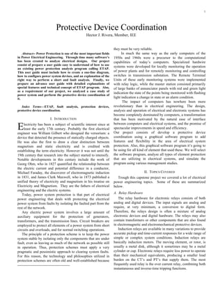
Other protective device is fuses. Fuses are designed for Fig.1 shows the original oneline diagram given to us
many different applications and with variety of characteristics with the objective of perform the protective device
to meet the requirements both routine and special situations. coordination. It does not include any protective device.
Fuses have different curves to realize these requirements. The
minimum melting curve is an average melting time measured
in low voltage test where arcing does not occur. Other curve is
total clearing curve should be used in coordinating against the
minimum melting characteristics of a larger fuse, located
toward the power source. Distribution fuses links are given
voltage ratings of 7.2, 14.4, and 17 KV nominal, or 7.8, 15,
and 18 KV maximum for use in open-link cutouts.
C. ETAP Program
ETAP seamlessly integrates the analysis of power control
circuits within one electrical analysis program. The control
system diagram simulates the sequence of the operation
control devices such as solenoids, relays, controlled contacts
multi-sequence contacts and actuators including inrush
conditions. The control system diagram has the capability of
determine pick-up and dropout voltage, losses and current Fig. 1. Original Oneline Diagram of Bayamón WWTP
flows at any time instance as well as overall margin and
critical alerts. A large library of equipment enables engineers C. Fault Simulation
to quickly model and simulate the action of relays associate Fig. 2 presents a three phase fault simulation at load 1.
with the control interlocks after given time delays. This fault provokes the operation of protective devices.
Operation times are showed in Fig. 3.
III. BAYAMON WWTP STUDY
A. Scope
Develop a short circuit study for Power Transformers and
relay settings for a waste water treatment plant and the
protective devices associated.
The Bayamón Waste Water Treatment Plant has seven large
power transformers with their respective protective devices
(power fuses or protective relaying) in service. The
intention of this short circuit study is to verify the
appropriated protective device coordination and
recommended the appropriated changes if any.
For this plant we will cover the relay coordination and
settings for the protective device associated.
The short circuit current available at Bayamón Waste
Water Treatment Plant, with 38 kV connection tap, is
submitted by Puerto Rico Electric Authority (PREPA).
Three phase short circuit current is 20,000 A and 11,547 A Fig. 2. Fault Simulation at Load 1 of BWWTP
for phase to ground.
The ETAP Power Simulation computer program, version
5.5 from Operation Technology, Inc was used for all the
short circuit studies and simulations.
The following tables detail information available for the
electrical equipment from the electrical drawings for
3. 3
Line to ground Fault
Operating Short
Localization
Voltage Circuit Operation Protection Devices Time (Cycles)
Fault
(kV) Current
Fuse 1/5 Fuse 2/6 Fuse 3/4/7/8 Fuse 9 Relay(50) Relay(51)
T1, T4 Primary 38 0A -------- -------- -------- -------- -------- --------
T1, T4
4.16 0A -------- -------- -------- -------- -------- --------
Secondary
Bus1, Bus 6 4.16 10,730 A -------- -------- -------- -------- 0 23.10
Bus2 , Bus 3 4.16 10,180 A -------- 1.62 -------- -------- 0 23.10
T2 , T3, T5 , T6
4.16 10,180 A -------- 1.62 5.7 -------- -------- 23.10
Primary
T2 , T3, T5 , T6
0.48 41,060 A -------- -------- 48.78 -------- -------- --------
Secondary
T7 Primary 4.16 10,730 A -------- -------- -------- -------- 0 23.10
T7 Secondary 0.48 6,850 A -------- -------- -------- 14.34 -------- --------
Fig. 5. Line to Ground Fault Results
Fig. 3. Sequence of Operations Events at Load 1 The figure above shows line to ground fault at different
areas of system. This kind of fault change operation time of
A fault at transformer 2 or 3 has a protection in devices. However, protective device coordination still
secondary side. Fuse 3 will operates like a back up with 25 working the same. All points reach coordination criteria of
cycles of different between primary protections. If fuse 3 23 to 25 cycles between coordination levels. Results was
does not operate, fuse 2 will operate with 25 cycles different verified with manual calculations and using ETAP software.
between the fuse 3. Bayamon WWTP has two emergency backup generators
A Three Phase Fault is happened in the secondary side of in case of PREPA faults. For that reason we perform a short
the transformer 7 (BTS-12). The transformer capacity is circuit simulation of this power system using generators.
0.15 MVA and the connection is Delta-Wye. The Our results are displayed below (Fig. 6 and 7).
impedance viewed at this point is by the utility, two Three Phase Fault
transformers and lines. The short circuit current is 6,687A.
Operated
When the Line to Ground Fault occur the zero sequence Localization
Voltage
Short Circuit
Operation Protection Devices Time (Cycles)
Fault Current
impedance is open by the primary side of the transformer 7 (kV)
Fuse Fuse Fuse
Fuse 9 Relay G(50) RelayG(51)
(BTS-12). The short circuit current at the secondary side of 1/5 2/6 3/4/7/8
the transformer is 6,855A. Bus1, Bus 6 4.16 258,532.1 A -------- -------- -------- 0 0 17.91
As the same way, we simulate faults trough all system. Bus2 , Bus 3 4.16 112,864.33 A -------- 0 -------- -------- -------- 18.06
T2 , T3, T5, T6
Results are showed at Fig. 4. Secondary
0.48 56,673.16 A -------- 0.78 5.4 -------- -------- 65.58
T7 Secondary 0.48 7,193.37 A -------- -------- -------- 1.8 -------- --------
Three Phase Fault
Localization
Operating Short Fig. 6. Three Phase Fault Results Using Generators
Voltage Circuit Operation Protection Devices Time (Cycles)
Fault
(kV) Current
Fuse1/5 Fuse2/6 Fuse3/4/7/8 Fuse9 Relay(50) Relay(51) Line to ground Fault
T1, T4 Primary 38 20,000A 1.44 -------- -------- -------- -------- --------
T1, T4
4.16 10,504 A 44.70 -------- -------- -------- -------- -------- Localization Operated Short Circuit
Secondary
Fault Voltage Current Operation Protection Devices Time (Cycles)
Bus1, Bus 6 4.16 10,500 A 44.82 -------- -------- -------- 0 19.5
(kV)
Bus 2, Bus 3 4.16 9,950 A 49.62 1.62 -------- -------- -------- 23.64 Fuse 1/5 Fuse 2/6 Fuse Fuse 9 Relay(50) Relay(51)
T2, T 3 , T5 , T6 3/4/7/8
4.16 9,950 A -------- 1.62 5.88 -------- -------- 23.64 336,678,51 A -------- -------- -------- 0 0 18.0
Primary
Bus 1, Bus 6 4.16
T2, T 3 , T5 , T6
0.48 35,440 A -------- 50.4 23.76 -------- -------- 75.78
Secondary 140,244.95 A -------- 0 -------- -------- -------- 18.0
Bus2 , Bus 3 4.16
T7 Primary 4.16 9,950 A 49.62 1.62 -------- -------- -------- 23.64
T2 , T3, T5, T6 57,815.87 A -------- 33.6 5.58 -------- -------- 33.6
T7 Secondary 0.48 6,690 A -------- -------- -------- 7.98 -------- -------- 0.48
Secondary
T7 Secondary 7,164.46 A -------- -------- -------- 1.8 -------- --------
0.48
Fig. 4. Three Phase Fault Results
We realized a three phase fault through BWWTP power Fig. 7. Line to Ground Fault Results Using Generators
system using PREPA connection. Our evaluation criteria to
all faults were 23 to 25 cycles of difference between When Bayamón WWTP is working with generators is
coordination levels. Figure 4.60 shows the short circuits possible that faults could happen. For that reason we made
magnitudes at the points analyzed. It also includes protective device coordination for BWWTP using
operation time for each equipment. generators. For a three phase fault at generators the
We also perform short circuit simulation of phase to overcurrent relay operates. If a fault occurs in system far
ground fault. All results are present at Fig. 5. from generators, protective devices work faster than when
using utility. It reduces time between coordination devices.
Coordination results are showing in table below.
4. 4
IV. RESULTS
Power Fuses Selection
Power Transformers T1, T2, T3, T4, T5, T6 and T7. The
Power Fuse Time Coordination show the analysis for the short
circuit simulations at the utility side and the power plant side
for the T1, T2, T3, T4, T5, T6 and T7. The fuse coordination
complies with time (12-30cycles) permitted by each
coordination. The following table (Fig. 8) shows the power
fuse summary for the transformers.
# Power Transformer Recommended Power Fuse Curve
1 T1 38/4.16 SMD-2C-100E Slow Speed
2 T2 4.16/0.48 SMU-40-300E Slow Speed
3 T3 4.16/0.48 SMU-40-300E Slow Speed
4 T4 38/4.16 SMD-2C-100E Slow Speed
5 T5 4.16/0.48 SMU-40-300E Slow Speed
6 T6 4.16/0.48 SMU-40-300E Slow Speed
7 T7 4.16/0.48 SMU-40-30E STD Speed
8 Main Feeder Fault Fiter-600 Time-delayed
Fig. 8. Recommendations to Fuse Protection
V. REFERENCES
[1] J. F. Fuller, E. F. Fuchs, and K. J. Roesler, "Influence of harmonics on
power distribution system protection," IEEE Trans. Power Delivery, vol.
3, pp. 549-557, Apr. 1988.
[2] E. H. Miller, "A note on reflector arrays," IEEE Trans. Antennas
Propagat., to be published.
[3] R. J. Vidmar. (1992, Aug.). On the use of atmospheric plasmas as
electromagnetic reflectors. IEEE Trans. Plasma Sci. [Online]. 21(3), pp.
876-880. Available: http://www.halcyon.com/pub/journals/21ps03-
vidmar
[4] E. Clarke, Circuit Analysis of AC Power Systems, vol. I. New York:
Wiley, 1950, p. 81.
[5] G. O. Young, "Synthetic structure of industrial plastics," in Plastics, 2nd
ed., vol. 3, J. Peters, Ed. New York: McGraw-Hill, 1964, pp. 15-64.
[6] J. Jones. (1991, May 10). Networks. (2nd ed.) [Online]. Available:
http://www.atm.com
[7] E. E. Reber, R. L. Mitchell, and C. J. Carter, "Oxygen absorption in the
Earth's atmosphere," Aerospace Corp., Los Angeles, CA, Tech. Rep.
TR-0200 (4230-46)-3, Nov. 1968.
[8] S. L. Talleen. (1996, Apr.). The Intranet Architecture: Managing
information in the new paradigm. Amdahl Corp., Sunnyvale, CA.
[Online]. Available: http://www.amdahl.com/doc/products/bsg/intra/
infra/html
[9] D. Ebehard and E. Voges, "Digital single sideband detection for
interferometric sensors," presented at the 2nd Int. Conf. Optical Fiber
Sensors, Stuttgart, Germany, 1984.
[10] Process Corp., Framingham, MA. Intranets: Internet technologies
deployed behind the firewall for corporate productivity. Presented at
INET96 Annu. Meeting. [Online]. Available: http://home.process.com/
Intranets/wp2.htp
[11] J. L. Alqueres and J. C. Praca, "The Brazilian power system and the
challenge of the Amazon transmission," in Proc. 1991 IEEE Power
Engineering Society Transmission and Distribution Conf., pp. 315-320.
[12] S. Hwang, "Frequency domain system identification of helicopter rotor
dynamics incorporating models with time periodic coefficients," Ph.D.
dissertation, Dept. Aerosp. Eng., Univ. Maryland, College Park, 1997.
[13] IEEE Guide for Application of Power Apparatus Bushings, IEEE
Standard C57.19.100-1995, Aug. 1995.
[14] G. Brandli and M. Dick, "Alternating current fed power supply," U.S.
Patent 4 084 217, Nov. 4, 1978.
shed (January 1, 1993).