IDEA StatiCa Seel Connections - seminar Genk/Kortrijk nov 2016

Wat leert u tijdens dit IDEA Steel Connect 7 release show? Wij gaan dieper in op de nieuwe mogelijkheden van release 7.0 en 7.1 vab IDEA Steel Connection rekensoftware voor het ontwerpen en controleren van staalverbindingen volgens de Eurocode 3. De unieke CBFEM methode van IDEA Connection stelt de gebruiker in staat om willekeurige verbindingen - van zeer eenvoudig tot uitertst complex - te controleren volgens de Eurocode 3 en de Amerikaanse norm. Idea Connection kan worden gebruikt als een op zich zelf staand programma of gelinkt aan uw bestaande reken- en tekensoftware. Graag nodigen wij u persoonlijk uit om verder kennis te maken met IDEA Connection versie 7.1. in Genk (wo. 23 november 9u-12u) of in Kortrijk (wo. 23 november 16u-19u).

Recommandé
Recommandé
Contenu connexe
En vedette
En vedette (20)
Similaire à IDEA StatiCa Seel Connections - seminar Genk/Kortrijk nov 2016
Similaire à IDEA StatiCa Seel Connections - seminar Genk/Kortrijk nov 2016 (20)
Plus de Jo Gijbels
Plus de Jo Gijbels (20)
Dernier
Dernier (20)
IDEA StatiCa Seel Connections - seminar Genk/Kortrijk nov 2016
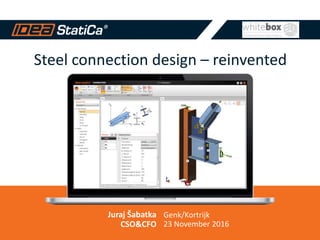
- 1. Steel connection design – reinvented Juraj Šabatka CSO&CFO Genk/Kortrijk 23 November 2016
- 2. 2 IDEA STATICA FOR STRUCTURAL ENGINEERING Development team with 20 years of experience of making innovative software for structural engineers in more than 40 countries. 2
- 3. Engineering software dedicated to structural design and code-check of joints, cross sections, beams and other details. 1000+ desktop licenses Software results validated by universities Linked to 12+ CAE/CAD programs 30+ employees 15+ resellers
- 4. 4 1 MAKING YOUR PROJECTS SAFE AND CODE COMPLIANT 4
- 5. 55 CAE PROGRAMS Focus on the model of the whole structure.
- 6. 66 STRUCTURAL DEFECTS But the majority of defects is caused by bad design of a particular joint or other detail. Waste of time Waste of material
- 7. 7 IDEA STATICA FOCUSES ON JOINTS AND CONNECTIONS 7
- 8. 88 IDEA STATICA COMPLEMENTS WHAT YOU HAVE Whole structure Structural details Low resources Big resources
- 9. 99 IDEA StatiCa is the first one to provide SW for joints and connections with development capacity and professionalism of CAE programs.
- 11. 1111 WE WANT TO BE ON THE SAFE SIDE To comply with Eurocode, AISC, etc.
- 13. 1313 STANDARD Easy joint NON-STANDARD Difficult joint Design books Advanced scientific model Excel spreadsheet Estimation Avoid using the joint
- 14. 1414 30 % Difficult joint 70 % Easy joint 30 % Easy joint 70 % Difficult joint NUMBER OF JOINTS TIME SPENT
- 15. 1515 We are here with a tool to check all structural steel joints in minutes.
- 16. 16 3 SOLUTION 16
- 17. 1717 ALL TYPES OF JOINTS 2D Frames & Trusses Footing & Anchoring 3D Frames & Trusses
- 18. 1818 DESIGN WITH IDEA STATICA CONNECTION Stress-strain Buckling Analysis Stiffness Analysis Overall Check
- 19. 19 Stress-strain Buckling analysis Stiffness analysis Overall check 19 ELECTRICITY TOWER MAST – POLAND Huge normal force loads the group of bolts eccentrically. Bolts cannot take this. Rearranging of bolts solved the problem.
- 20. 2020 Stress-strain Buckling analysis Stiffness analysis Overall check STEEL WAREHOUSE – GERMANY Connection fully satisfies all stress/strain checks But the web of the beam can collapse because of local buckling Additional stiffener resolved this problem
- 21. 21 Stress-strain Buckling analysis Stiffness analysis Overall check 21 POWER PLANT – CZECH REPUBLIC Ovalization of CHS. Stiffness perpendicular to CHS is weaker. All CHS are welded to one plate. Stiffness is 10x higher.
- 22. 22 Stress-strain Buckling analysis Stiffness analysis Overall check 22 HEATHROW AIRPORT – UK Connection was not designable with the suggested prescribed EC3 requirements and a more generic analysis approach had to be adopted.
- 23. 2323
- 24. 24 TESTIMONIAL FRISOMAT 24 “IDEA Connect werkt vlot en snel. Er is geen gebruiksvriendelijker alternatief voorhanden dat toelaat FEM met CBM te combineren. IDEA is gewoon degelijk en goed.” Prof. Dr. Ir. Luc Schueremans Engineering Manager
- 25. 2525 Any topology, any loading, in minutes.
- 26. 26 4 CREDIBILITY 26 Verification and validation of the new CBFEM method.
- 27. 27 COMPONENT BASED FINITE ELEMENT MODEL (CBFEM) The weak point of standard Component method Design guides is that the topology is limited. 27 Component Model Bolted Joint CBFEM model
- 28. 2828 All standard connections from Eurocode / AISC design guides, calculated with the same results.
- 29. 2929 Complex FEA analytical models were compared with IDEA. Same results.
- 30. 3030 VERIFICATION – COMPLEX TOPOLOGIES Tailor-made design models created in various software. Live testing. All studies published. Two university teams spent over 3 years on this.
- 31. 31 COOPERATION WITH UNIVERSITIES = VERIFIED SOLUTION 31 ORDER TODAY
- 32. 32 There is sophisticated method inside. It was verified and transformed into a tool how to create joints. 32
- 34. 34 TESTIMONIAL OOSTINGH STAALBOUW KATWIJK 34 Alexander van Beelen “Geeft beter en ook nieuw inzicht in de krachtswerking in verbindingen. Rapportage mag nog watverbeterd worden.”
- 35. 35 5 WORKFLOW 35
- 36. 3636 BIM INTERFACE – CAD PROGRAMS Tekla Structures and Advance Steel. Node Selection in AS Input of Load Effects Check EN / AISC
- 37. 3737 BIM INTERFACE – FEA PROGRAMS Robot, SAP 2000, SCIA Engineer, RFEM, AxisVM etc. (Buildsoft Diamonds coming) Node Selection in RSA Design of Connection Check EN / AISC
- 38. 3838 IDEA StatiCa would not build such strong links without having strong relationships with the key players in our industry.
- 41. 4141 CLIENTS
- 42. 4242 BENELUX
- 43. 43 TESTIMONIAL STAALBOUWKUNDIG ADVIESBURO VAN ODENHOVEN 43 Marcel van Odenhoven “Idea Connection is een zeer behulpzaam pakket voor het modelleren van een breed scala van verbindingen in staalconstructies. Het modelleren en interpreteren van de resultaten vraagt inzicht in de krachtswerking binnen een knoop en gaat gelijk op met de complexiteit van de verbinding.”
- 44. 4444 600Licenses around the world 150 Tekla users bought it already
- 46. Tool needs to… Allow efficient workflows through interoperability Be simple to learn and use Be fully supported by codes and validated theory Be used for concept through to detailed design Arup use of IDEA StatiCa Connection
- 47. 10 years ago….
- 48. Tekla Drawing Model Rhino Transition Model Excel Load Input D3 Plot Stress checks Excel/VB Weld checks ANSA Meshing Nastran Analysis GSA Global Analysis Modelling, Analysis, Design, Fabrication
- 49. …..Now Original model (days) IDEA StatiCa (in minutes)
- 51. Arup use of IDEA StatiCa Connection
- 52. Arup use of IDEA StatiCa Connection
- 53. Arup use of IDEA StatiCa Connection
- 54. Arup use of IDEA StatiCa Connection
- 55. Arup use of IDEA StatiCa Connection
- 56. Arup use of IDEA StatiCa Connection
- 57. ARUP and IDEA StatiCa at Autodesk University, Las Vegas, 2016
- 59. 5959 REPORTING We support Eurocode and AISC. Various sets of material types, cross-sections, bolts, etc. Different types of reports. Schemes of drawings.
- 60. 6060 OUTPUT REPORT Three types of output reports – one line, 1 page and detailed. All checks according to Eurocode or AISC displayed and referenced.
- 61. 61 CUSTOMER PROJECT CEPS – Electricity Tower Masts 61 Special request for manufacturing operations. Developed in 8 weeks. We also provided consultancy
- 62. 62 CASE STUDY CEPS INVEST 62 Cenek Laub Head of engineering department “Maintaining and developing electricity network in the Czech Republic is full of challenging tasks. With IDEA StatiCa Connection, joint design got much easier and faster for us.”
- 63. 6363 We are here with not just a standard application but also with an infrastructure to build a tailor-made solution.
- 64. 6464 95 %of our customers saw the potential of IDEA StatiCa after 30 minutes of testing.
- 65. TRY OUR FREE TRIAL! It takes 30 minutes to see the potential Our customers use it for non-standard joints as well as standard ones The software repays itself on your first project
Notes de l'éditeur
- Add Dlubal/Buildsoft
- This Slide shows the process used by the BIM modellers and the structural engineers – This workflow is for the node design, there were other used for the main super structure, north core and floor plate design. Initially we modelled the nodes as “crashing plates”, then from the Tekla model (.stp file) was generated and imported into Rhino to clean up the volumes and into the meshing software ANSA, creating simple finite element models with which we could study the structural behaviour in more detail. At the same time the loads from the structural analysis were being processed using excel in order to identify the critical load combinations. The analysis itself was then carried out using Nastran and was supported by tools we developed in-house. D3 plot facilitates the search for high stress concentrations by enabling the user to cut sections through the analysis results in real time. We also wrote some Excel visual basic routines which calculated the stresses in the welds. Once the design was completed the data was fed back to the BIM modellers and incorporated. Arup fully designed the nodes at lower levels prior to tender, in order to give confidence to the contractors when they were pricing the job. For these final design checks we used a similar process to that employed during scheme design, but with some more sophisticated analysis tools. There are over 100 mega frame nodes on the project, some similarities between various nodes but Arup is still responsible for around 40 individual nodes. As you can imagine this process mean close collaboration with the structural engineer, architect and later in the process the fabricator to develop the details in a way which ensured that they were buildable and yet also met the architectural intent.