1. CHAPTER II
MEDCO SINGA CPP DESCRIPTION
2.1. OPERATIONS and PROCESS
LNG processing facility Singa Central Processing CPP is the operating phase of the separation and
purification of natural gas from four (4) existing wells in field. STAGEs of processing operations of gas flow
from the well done aims to meet the specifications of the desired gas by Perusahaan Gas Negara (PGN)
unit area of South Sumatra. Production capacity at Singa Field CPP each well by 30 MMSCFD.
1. the Gas processing Unit Singa CPP consists of:
a. Gas Gathering System,
b. Separation System
c. Acid Gas Removal System
d. Dehydration Unit System,
e. Thermal Unit Oxidasi,
f. Sales Gas Pipeline and Pagardewa Receiving Facilities
2. Supporting Utilities Unit consisting of:
g. the Thermal Fluid System,
h. Closed Drain System.
i. Water Treatment Unit * Fire Water,
j. Produced Water/Disposal
k. Unit Power generators, Diesel Fuel System
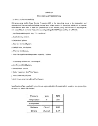
Specification of gas supplied from wells and processed at the Processing Unit based on gas composition
of Singa CPP Wells. is as follows:
Pressure psig 1270
Temperature F 250
Component
Methane (% mol) 61.20
Ethane (% moll) 0.17
2. Propane (% mol) 0.01
i-Butane (% mol) 0.01
CO2 (% vol) 38.41
N2 (% mol) 0.03
H2S (% mol) 0.035
H2O (% mol) -
Molar Flow
93
MMSCFD
(Dry
Basis) HP
Case
Tabel-1 Gas Supplied Specification
2.2 Specifications Gas Products‐Gas products from Singa CPP sent to Surrender Station Pagardewa must
meet specifications request buyer, in this case the Perusahaan Gas Negara (PGN). The flow of gas products
received by PGN through terminal facilities at Pagardewa acceptance is as follows:
Pressure psig 1050
Temperature F 98.5
HC dew Point,
max. pada
1050psig
oF 55
Methane %-mol 96.2693
Ethane %-mol 0.2778
Propane %-mol 0.0165
i-Butane %-mol 0.0165
CO2 %-vol 4
N2, max. %-mol 5
H2S, max. ppm-vol 4
H2O Lb/MMSCF 8
3. Molar Flow
50
MMSCFD
HP Case
Sources of gas well production comes from four well with the amount of 116.8 MMSCFD at a temperature
of 250 ° F and 375 psig pressure with specification as aforesaid. Each of the well done analysis of
composition and condensate content periodically, alternating for 4 hours with Test Separator. The Gas
produced from the well production is that the corrosive gas elements due to its high content of CO2. Of
the four streams of gas wells walked into the gathering system or system of manifold. There are 3 manifold
or header for which the supply of gas flow from the well came in, the first a header/manifold blowdown
serves to transfer or release pressure in the system when the primary process occurs the excesses of
pressure or problems on the gas plant. The System is equipped with a blowdown valve (BDV) to cope with
emergencies. the BDV on blowdown line will open automatically and siphon the gas to the Flare
KNOCKOUT Drum, so on gas flow to the Flares, while the shutdown valve (SDV) on line main process will
close so that no gas was flowing into the gas plant. Second is the manifold/header for on‐site sampling
routine. The Gas flows into the separation tank test 31‐MBD‐102 after through the inlet separator 31‐
MBD‐127 and water cooler blower 31‐201. Manifold/header to‐3 or called with production manifold, here
also passed inlet gas flow separator tank 31‐MBD‐127, water cooler blower 31‐201 and production
separator. The inlet separator 31‐MBD‐126 and 31‐MBD‐109, flushing occurs due to the high‐pressure
flow of gas towards lower pressure causing the liquid phase separation occurs in the gas phase. Phase
liquid in the gas so we refer to as condensate, containing heavy hydrocarbon and water. The condensate
is accommodated in the inlet separator 31‐MBD‐127, test separator 31‐MBD‐102 and production
separator 31‐MBD‐101 each vessel have a level controller for controlling the level/flow unit condensate
Produced Water Disposal System. The gas Separation Unit output feedback to CO2 Removal with the
condition of the process:
Pressure 1235 psig 1055 psig
Temperature 119.3 oF 119.3 oF
Component % mole % mole
Methane 61.1923 61.1788
Ethane 0.1700 0.1699
Propane 0.0100 0.0100
i-Butane 0.0100 0.0100
CO2 38.2936 38.2928
N2 0.0300 0.0300
H2S 0.0346 0.0346
H2O 0.2595 0.2739
Standard Gas
Flow
93
MMSCFD
HP Case
90
MMSCFD
LP Case
5. of the flow of the lean amine in transferred to the Amine Charcoal Filter 35‐JANG‐109 and Amine
Particulate After filter‐35‐JANG‐111 to take contaminant particles and later transferred to both
Amine Absorber using pump 35‐PBA‐334A/B.
3. Acid Gas System
Acid gas out of the flash column on 12 psig and 161 oF and cooled with condenser 35‐HAL‐203 to
temperature 140 oF. The flow out of the condenser is a mixture of water and acid, into the
accumulator 30‐MBD‐109 which served as a gas‐liquid separator. Acid gas passing through the
accumulator to the Thermal Oxidizer (T‐Ox). The water that goes into the bottom of the
accumulator flow Flash Column using a reflux pump 35‐PBA‐332A/B. Acid gas is burned inside
the chimney Thermal Oxidizer before safely and in accordance with the gas quality emissions
government regulation role to be released into the atmosphere through the vent stack.
A. Antifoam Injection System
Antifoam Injection System was installed to minimize Antifoam injection of foam (foam) in the
amine system. Flow injection antifoam are:
• Suction of the Reflux Pumps (35‐PBA‐332A/B)
• Suction of Rich Pumps (35‐PBA‐333A/B)
• Suction of Lean Pumps (35‐PBA‐334A/B)
B. Membrane Unit
STAGE I Membrane Pre Treatment System of gas filter Gas Feed 45 MILLION towards the
membrane unit and the rest flows to the amine unit. The Feed gas at 1230 psig and 119 0F entered
the tube side of the Gas/Gas Exchanger 35‐HBG‐281 in the chill to the temperature of the gas
residue 88 oF Membrane Skid Package STAGE I. A Gas has on the chill in the First STAGE Filter
Coalescer 35‐MAJ‐175 to eliminate the water and the condensed hydrocarbons. Vapor at 1223
psig and 87oF streamed to the First STAGE Electrical Heater 35‐NAP‐681 to raise the temperature
to 109 oF. The Feed gas is then transferred to the First STAGE Guard bed 35‐MBA‐182 and First
STAGE Particle Filter 35‐JANG‐183 for the first.
B.1. STAGE I Membrane Skid Package Each membrane is made up of four skids of bank with 7
pieces of tube, membrane tube has four nozzle: A nozzle the inlet feed‐gas. ‐One nozzle for
residual gas outlet. ‐Two nozzle to permeate outlet gas. Separex membrane elements made from
cellulose acetat which has two layers: the thick micro porous layer and a thin active layer on top
of the micro porous layer. The Feed gas into the tube membrane and distributed into membrane
meliwati high pressure channel spacer. Along the way the gas inside the tube membrane, CO2,
H2S, and other materials which are highly permeable to quickly penetrate the membrane to reach
into a permeate channel spacer. Components permeate this move with spiral patterns in a tube
to permeate tube. Components with such a small permeable methane power missed in high
pressure channel spacer next element flows into or out of the membrane tube, go to residual
header. The flow of incoming feedback flow freely from the element to the element on the eve
of the U‐cup seal installed in upstream side of each element. Each tip out the covered with epoxy
membrane elements. The Feed gas enters Membrane Skid Package STAGE I in 1210 psig and
109oF. Unit membrane lowers CO2 and H2S from the gas feed 38.4 mole% down to 4% mole and
H2S 346 ppm‐v down to 18 ppm‐v, each producing gas 24.7 MMSCFD. Then the gas is heated by
Gas/Gas Exchanger 35‐HBG‐281 up to 111 oF. Due to the high content of H2S is still high, mounted