1. Chapter 7 Cable Installation
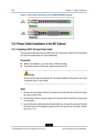
Figure 7-18 DC Power Distribution of the ZXSDR BS8900A Cabinets
7.5.1 Power Cable Installation in the BC Cabinet
7.5.1.1 Installing a B121 AC Input Power Cable
This procedure describes how to install a B121 AC input power cable for the three-phase
AC input and single-phase AC input respectively.
Prerequisite
l Before the installation, you must wear an ESD wrist strap.
l The tributary output of the power supply has been cut off.
Danger!
Ensure that the cabinet is powered off. The cable installation with power on can result
in personal injury or even death.
Steps
1. Remove the cover plate of the AC connection box at the left side of the B121 power
by using a screw driver.
2. Cut the power cable in a proper length, and crimp the both connectors by using a pair
of crimp pliers.
3. Lay out the power cable along the left-side cable tray, through the waterproof module
on the left side of the baseband cabinet, and to the input end of the power module,
see Figure 7-19.
7-21
SJ-20150203110107-011|2016-03-23 (R1.1) ZTE Proprietary and Confidential
2. ZXSDR BS8900A Hardware Installation
Figure 7-19 External AC Input Cable Connections
4. Connect the AC input cable to the screw terminal of the B121 in accordance with the
AC power mode (three-phase or single-phase). For the screw terminal of the B121,
see Figure 7-19. When using the three-phase five-wire mode for AC input, connect
L1, L2, L3 and N of AC input to the corresponding L1, L2, L3 and N of the B121 power
AC-INPUT terminals. For the detailed positions, see 7.5 Power Cable Installation.
l If the AC power input uses the three-phase five-wire mode, connect L1, L2, L3,
and N of the AC input cable to L1, L2, L3, and N at the AC-INPUT terminal of the
B121.
l If the AC power input uses the single-phase mode, connect the phase wire L (red)
and neutral wire N (blue) to L1 and N at the AC-INPUT terminal of the B121.
5. Reseat the cover plate of the B121 power AC connection box, and fasten the bolts by
using the screw driver.
6. Connect the other end of the power cable to the AC output connector of an external
power supply.
– End of Steps –
7-22
SJ-20150203110107-011|2016-03-23 (R1.1) ZTE Proprietary and Confidential
3. Chapter 7 Cable Installation
7.5.1.2 Installing a B201 AC Input Power Cable
This procedure describes how to install a B201 AC input power cable for the three-phase
AC input and single-phase AC input respectively.
Prerequisite
l Before the installation, you must wear an ESD wrist strap.
l The tributary output of the power supply has been cut off.
Danger!
Ensure that the cabinet is powered off. The cable installation with power on can result
in personal injury or even death.
Steps
l Remove the four retaining screws at the four corners of the power switch cover plate
of ZXDU68 B201, and then remove the cover plate.
l Cut the power cable in a proper length, and crimp the both connectors by using a pair
of crimp pliers.
l Lay out the power cable along the left-side cable tray of the RF cabinet, through the
waterproof module on the left side of the baseband cabinet, and to the input end of
the power module.
l Connect the AC input cable to the screw terminal of the B201 in accordance with the
AC power mode (three-phase or single-phase). For the screw terminal of the B201,
refer to 7.5 Power Cable Installation.
à If the AC power input uses the three-phase five-wire mode, connect L1, L2, L3,
and N of the AC input cable to L1, L2, L3, and N at the AC-INPUT terminal of the
B201.
à If the AC power input uses the single-phase mode, connect the phase wire L (red),
neutral wire N (blue), PE to the corresponding AC-INPUT terminal of the B201.
The PE is connected to the grounding bar on the left side of the baseband cabinet.
l Reseat the cover plate of the B201 power AC connection box, and fasten the bolts by
using the screw driver.
l Connect the other end of the power cable to the AC output connector of an external
power supply.
– End of Steps –
7.5.1.3 Installing a DC Input Power Cable for the BC8910A Cabinet
This procedure describes how to install a DC input power cable for the BC8910A cabinet.
7-23
SJ-20150203110107-011|2016-03-23 (R1.1) ZTE Proprietary and Confidential
4. ZXSDR BS8900A Hardware Installation
Prerequisite
l Before the installation, you must wear an ESD wrist strap.
l The tributary output of the power supply has been cut off.
Danger!
Ensure that the cabinet is powered off. The cable installation with power on can result
in personal injury or even death.
Context
When using the -48 V DC power supply, only configure the DCPD6 instead of other powers.
Connect the DC input power cable to the DC input terminal of DCPD6.
Steps
1. Remove the cover plate of the connection box of DCPD6 DC-IN by using a screw
driver.
2. Cut the power cable in a proper length, and crimp the both connectors by using a pair
of crimp pliers.
3. Lay out the power cable along the left-side cable tray of the RF cabinet, through the
waterproof module on the left side of the baseband cabinet, and to the input end of
the power module.
4. Connect the –48 V end of the DC input power to the –48 V terminal of DCPD6 DC-IN,
and connect the –48 VRTN to the –48 VRTN terminal of DCPD6 DC-IN, see Figure
7-20.
Figure 7-20 Cable Connection of –48 V DC Input
5. Reseat the cover plate of the connection box of DCPD6 DC-IN., and fasten the bolts
by using the screw driver.
6. Connect the other end of the power cable to the AC output connector of an external
power supply.
– End of Steps –
7-24
SJ-20150203110107-011|2016-03-23 (R1.1) ZTE Proprietary and Confidential
5. Chapter 7 Cable Installation
7.5.2 Power Cable Installation in the RC Cabinet
7.5.2.1 Installing RC8910A DC Input Power Cables (BC8910A Cabinet Stacked with
RC8910A Cabinet)
This procedure describes how to connect the DC power cables of the RC8910A cabinet.
Prerequisite
l The ESD wrist strap must be worn.
l The tributary output of the power supply is cut off.
Danger!
Ensure that the cabinet is powered off. The cable installation with power on can result in
personal injury or even death.
Steps
1. Remove the cover on the connectors of the power subrack DC OUT.
2. On the DC output interface DC OUT on the right side of the power subrack, for
example, Load 3, connect one end of the blue –48 V cable to -48 V connector, and
connect one end of the black –48 V VRTN cable to the -48 V RTN connector.
For how to connect the connectors of the power subrack, refer to 7.5 Power Cable
Installation.
Note:
By default, some cables are installed on the BC8910A cabinet before delivery. During
the onsite installation, ensure that these cables are not loosened when installing other
cables.
3. Route these cables along the cable rack and the side of the BC8910A cabinet and
then through the cable-through holes on the right side of the RC8910A cabinet.
4. Connect one end of these cables to the -48 V and -48 V RTN power terminals on the
RC8910A cabinet.
5. Bundle and secure these cables.
– End of Steps –
7-25
SJ-20150203110107-011|2016-03-23 (R1.1) ZTE Proprietary and Confidential
6. ZXSDR BS8900A Hardware Installation
7.5.2.2 Installing a RC8910A DC Input Power Cable (RC8910A Cabinet Placed
Individually)
This procedure describes how to connect the DC input cable for a single RC8910A cabinet.
Prerequisite
l The ESD wrist strap must be worn.
l The tributary output of the power supply is cut off.
Steps
1. Connect one end of these cables to the -48 V and -48 V RTN power terminals on the
RC8910A cabinet.
2. Connect the other end of these cables to the DC output terminals of the DC power
supply.
3. Bundle and secure these cables.
4. Give waterproof treatments to the cables.
– End of Steps –
7.5.3 Installing DC Input Cables for the PC8910A Cabinet
This procedure describes how to connect the DC power cables of a PC8910A cabinet. The
DC power cable of the PC cabinet is used for charging batteries and powering the ZXSDR
BS8900A.
Danger!
Ensure that the cabinet is powered off. The cable installation with power on can result in
personal injury or even death.
Context
For how to connect the power cable of the battery, see Figure 7-21.
7-26
SJ-20150203110107-011|2016-03-23 (R1.1) ZTE Proprietary and Confidential
7. Chapter 7 Cable Installation
Figure 7-21 Battery Power Cable Connection
Prerequisite
l The ESD wrist strap must be worn.
l The tributary output of the power supply is cut off.
Steps
1. Remove the cover of the terminals on the top of the PC8910A cabinet.
2. Crimp the screw terminals, and then route the cables, see Figure 7-22.
7-27
SJ-20150203110107-011|2016-03-23 (R1.1) ZTE Proprietary and Confidential
8. ZXSDR BS8900A Hardware Installation
Figure 7-22 DC Power Cable Routing of the PC8910A Cabinet
1. -48 V RTN cable (red) 2. -48 V cable (blue)
Note:
l When the cable goes through the waterproof module, select a proper hole in
accordance with the cable diameter.
l The exposed cables must be protected with corrugated pipes.
l The cable-through holes are protected with waterproof plugs. Remove these
plugs before the cables are routed and then reset them.
3. Connect one end of the power cable to the power switch at the top of the PC cabinet.
The black cable is connected to the -48 V connector (BAT–) on the right side of the
power switch, and the red cable is connected to the -48 V RTN connector (BAT+).
7-28
SJ-20150203110107-011|2016-03-23 (R1.1) ZTE Proprietary and Confidential
9. Chapter 7 Cable Installation
4. Connect one end of the power cables to the ports of the B121 or B201 PDMs of the
BC8910A cabinet.
For the B121 and B201 PDMs, connect the power cable to the BATT Input interface
on the left side of the power subrack. Connect the red wire to the –48 V RTN screw
terminal, and connect the black wire to the –48 V screw terminal, see Figure 7-22.
5. Bundle the cables reliably and neatly along the side of the cabinet and the cabling
aperture on the bottom of the cabinet.
– End of Steps –
7.5.4 Installing a Fan Power Cable for the PC8910A Cabinet
This procedure describes how to install the fan power cables for air-ventilated and
thermoelectric-cooling PC8910A cabinets.
Prerequisite
The ESD wrist strap must be worn.
Steps
l Connecting the fan power cable for the air-ventilated PC8910A cabinet
1. Connect the fan power cable to the fan power port on the left wall of the PC8910A
cabinet, see Figure 7-23.
7-29
SJ-20150203110107-011|2016-03-23 (R1.1) ZTE Proprietary and Confidential
10. ZXSDR BS8900A Hardware Installation
Figure 7-23 Connecting the Fan Power Cable
2. Thread the fan power cable through the cable-through hole at the left bottom of
the PC8910A cabinet, and bind the cable along the wall of the PC8910A cabinet.
Thread the fan power cable through the base of the RC8910A cabinet, and route
the cable along the cable trough on the right of the RC8910A cabinet and the right
waterproof module of the BC8910A cabinet to the PDM of the BC8910A cabinet.
3. Connect the fan power cable to the DC output interface of the B121 or B201 PDM.
For the B121 and B201 PDMs, connect the fan power cable to the DC power
output port of the subrack, for example, Load 3, see Figure 7-23.
7-30
SJ-20150203110107-011|2016-03-23 (R1.1) ZTE Proprietary and Confidential
11. Chapter 7 Cable Installation
Note:
By default, some cables are connected to the power switches of the BC8910A
cabinet before delivery. During the onsite installation, ensure that these cables
are not loosened when installing other cables.
When a DPCP module is installed but no interfaces are left on the DC OUT of the
power subrack, the fan power cable of the PC cabinet can be connected to the
interface for the fan power cable of the BC cabinet. They share the same Load
interface. The fan power cable of the BC cabinet is installed before delivery.
l Connecting the fan power cable of the thermoelectric-cooling PC8910A cabinet
1. Figure 7-24 shows the fan power cable connection of thermoelectric-cooling
PC8910A cabinet.
Figure 7-24 Fan Power Cable Connections of the Thermoelectric Cooling
battery Cabinet
2. Connect the power cable to the DC power output terminals of the PDM.
– End of Steps –
7-31
SJ-20150203110107-011|2016-03-23 (R1.1) ZTE Proprietary and Confidential
12. ZXSDR BS8900A Hardware Installation
7.5.5 Installing the Power Cable of the Heater (Optional)
The heater is an optional component that can be installed in accordance with the device
operation environment.
This procedure describes how to install the power cable of the heaters for the BC8910A
cabinet and RC8910A cabinet. The power cable of the heaters in the BC8910A and the
RC8910A cabinets are connected to the AC OUTPUT ports. The AC OUTPUT ports are
beside the AC INTPUT port.
Prerequisite
l An ESD wrist strap must be worn.
l The power to the cabinets is off.
Context
The heater of the BC cabinet is required to be configured when the minimum temperature
is lower than -15°C.
AC power is supplied to the heater of the BC cabinet with a power consumption of 100 W.
The heater is 3/4U high and installed at the bottom layer of the BC8910 cabinet.
The PC8910A cabinet uses two heating films with a power consumption of 100 W. The
heating films are installed below the battery supporting plate by screws.
When the temperature is lower than the specified temperature, the temperature-controlling
switch of the heating films is closed, and the heating films start heating. The heat is
dissipated naturally to warm up the batteries.
Steps
l Installing the power cable of the heater in the BC cabinet
1. Connect the power cable of the heater to the AC OUTPUT screw terminal on the
left side of the PDM, see Figure 7-25.
7-32
SJ-20150203110107-011|2016-03-23 (R1.1) ZTE Proprietary and Confidential
13. Chapter 7 Cable Installation
Figure 7-25 Power Cable Routing of the Heater in the BC Cabinet
Note:
Before powering on the cabinet, verify that there is not short circuit between the
AC OUTPUT terminal and the cabinet by using a multimeter.
l Installing the power cable of the heater in the PC cabinet
1. Thread the power cable of the heater through the left waterproof module of the
PC cabinet, route the cable in to the BC cabinet through the cabinet base, and
connect the cable to the AC OUTPUT screw terminal on the left side of the PDM,
see Figure 7-26.
7-33
SJ-20150203110107-011|2016-03-23 (R1.1) ZTE Proprietary and Confidential
14. ZXSDR BS8900A Hardware Installation
Figure 7-26 Power Cable Routing of the Heater in the PC Cabinet
– End of Steps –
7.5.6 Installing the Power Cable for a Remote RRU (Optional)
If remote RRUs are connected, the ZXSDR BS8900A needs to power the RRUs. This
procedure describes how to connect the power cable from the ZXSDR BS8900A to a
remote RRU.
If RRUs are connected, the DCPD6/DCPD7 modules are configured in the baseband
cabinet. The DCPD module provides power for RRUs.
Prerequisite
l An ESD wrist strap must be worn.
l The power to the cabinets is off.
Steps
1. Lay out the power cable along the right-side cable tray of the RF cabinet, through the
waterproof module on the right side of the baseband cabinet, and to the output end of
the power module, see Figure 7-27.
7-34
SJ-20150203110107-011|2016-03-23 (R1.1) ZTE Proprietary and Confidential
15. Chapter 7 Cable Installation
Figure 7-27 RRU Power Cable Connections
2. Fabricate the connector of the power cable on the DCPD side with a pair of crimp
pliers, and connect the connector to the DC output interface of the DCPD.
3. Fabricate the connector of the power cable on the RRU side, and connect the
connector to the power interface of the RRU.
– End of Steps –
7.6 Transmission Cable Installation
The ZXSDR BS8900A uses either optical fibers or Ether cables as transmission cables.
Transmission cables are determined based on particular situations.
7-35
SJ-20150203110107-011|2016-03-23 (R1.1) ZTE Proprietary and Confidential
16. ZXSDR BS8900A Hardware Installation
7.6.1 Installing Transmission Fibers (Optional)
This procedure describes how to install the optical fibers connecting the BC8910A cabinet
to transmission devices..
The transmission fibers of a base station transmit S1-/X2-interface signals.
Prerequisite
The ESD wrist strap must be worn.
Context
The following requirements must be met when you install optical fibers:
l Do not damage the optical fiber cladding during operations.
l Protect optical fiber connectors and avoid contaminating them.
l Do not forcibly bundle optical fibers.
l Curve optical fibers at the turning.
The following requirements must be met when you bind the cables:
l The cables must be bound in order. The cables of the same category must be adjoined
closely.
l To bend the bound cables, the cable clips should be tied at two sides of the corner to
avoid wire breaks.
Steps
1. Paste temporary labels.
Paste temporary labels at both ends of the new optical fiber to set up a mapping. If
more than one optical fiber needs to be installed, use different labels to distinguish the
optical fibers.
2. Lay out optical fibers.
One ends of the optical fibers are connected to the external transmission device. The
other ends of the optical fibers are threaded through the cabinet base, and routed along
the left cable trough of the RC8910A cabinet and along the left waterproof module
of the BC8910A cabinet to the optical interface TX/RX on the BBU CC board in the
BC8910A cabinet. For the routing of the optical fibers, see Figure 7-28.
7-36
SJ-20150203110107-011|2016-03-23 (R1.1) ZTE Proprietary and Confidential
17. Chapter 7 Cable Installation
Figure 7-28 Optical Fiber Routing
3. Insert optical fiber connectors to the corresponding TX/RX interfaces in accordance
with the labels on the optical fibers..
Caution!
Insert optical fiber connectors tightly.
4. Bundle the optical fibers.
Bundle and secure optical fibers along the routing troughs, which complies with
relevant regulations about optical fiber binding.
7-37
SJ-20150203110107-011|2016-03-23 (R1.1) ZTE Proprietary and Confidential
18. ZXSDR BS8900A Hardware Installation
5. Paste an engineering label on an optical fiber.
Remove the temporary label for the optical fiber and paste an engineering label.
Caution!
Protect an optical fiber with the winding tube when routing the optical fiber inside the
cabinet. Protect an optical fiber with the corrugated pipe when routing the optical fiber
outside the cabinet.
– End of Steps –
7.6.2 Installing Ethernet Cables (Optional)
This procedure describes how to connect the Ethernet cable from the baseband cabinet
to transmission devices.
Prerequisite
The ESD wrist strap must be worn.
Steps
1. Lead one end of the Ethernet cable through the cable hole.
2. Thread the Ethernet cable through the base of the floor-mounting cabinet (PC8910A or
RC8910A), route the cable along the left cable trough of the RC8910A cabinet, thread
the cable through the waterproof module at the left bottom of the BC8910A cabinet into
the BC8910A cabinet, and then connect the cable to the ETH_0 or ETH_1 interface
of the LPU, see Figure 7-29.
7-38
SJ-20150203110107-011|2016-03-23 (R1.1) ZTE Proprietary and Confidential
19. Chapter 7 Cable Installation
Figure 7-29 Ethernet Cable Routing
Note:
The Ethernet cable between the LPU and the ETH interface of the CC board is installed
before delivery. During the onsite installation, ensure that the both ends of the Ethernet
cable are connected securely.
3. Connect the other end of the Ethernet cable to a proper interface of the switch.
4. Bundle the Ethernet cable and paste an engineering label to the Ethernet cable.
– End of Steps –
7-39
SJ-20150203110107-011|2016-03-23 (R1.1) ZTE Proprietary and Confidential
20. ZXSDR BS8900A Hardware Installation
7.7 Signal Cable Installation
For the signal cables of the ZXSDR BS8900A, see Figure 7-30.
Figure 7-30 Signal Cables of the ZXSDR BS8900A
1. SFP cable
2. Outdoor fiber
3. GPS cable
4. Antenna feeder
5. AISG cable
7.7.1 Installing an Interconnected Cable Between BBU and RSU
This procedure describes how to install SFP cables.
7-40
SJ-20150203110107-011|2016-03-23 (R1.1) ZTE Proprietary and Confidential
21. Chapter 7 Cable Installation
In the ZXSDR BS8900A system, optical fibers or SFP cables can be used to connect
the BBU and RSU. During the stacked installation of the ZXSDR BS8900A, a 2 m SFP
high-speed cable is recommended for interconnecting the BBU and RSU.
Prerequisite
The ESD wrist strap must be worn.
Steps
1. Paste temporary labels at both ends of the SFR cable, and mark 0-5 to set up
one-to-one mapping with interfaces TX0RX0 to TX5RX5 of BBU and six TX/RX
interfaces of RSU.
2. Insert one end of the SFP cable to a TX/RX interface of RSU.
3. Route the SFP cable along the routing trough and cabinet sides to the FS module of
BBU. The SFP cables connecting to the RSUs in slots 1 to 3 on the RC8910A cabinet
go through the left cable-through holes and those SFP cables go through the right
apertures if connecting to slots 4 to 6 on the RC8910A cabinet, see Figure 7-31.
7-41
SJ-20150203110107-011|2016-03-23 (R1.1) ZTE Proprietary and Confidential
22. ZXSDR BS8900A Hardware Installation
Figure 7-31 SFP Cable Layout
4. Insert SFP cables into the interfaces TX0RX0 to TX5RX5 of the BBU FS board in
accordance with the markings 0–5.
5. Bundle the SFP cables.
6. Remove the temporary labels and paste engineering labels.
– End of Steps –
7-42
SJ-20150203110107-011|2016-03-23 (R1.1) ZTE Proprietary and Confidential
23. Chapter 7 Cable Installation
7.7.2 Installing Outdoor Fibers (Optional)
This procedure describes how to connect the optical fiber between the baseband cabinet
and the remote RRU. When the ZXSDR BS8900A connects RRUs, outdoor fibers need to
be installed.
If the baseband cabinet and RF cabinet are installed in parallel or the distance between
the cabinets is long, outdoor fibers are required to connect the BBU and RSU.
Prerequisite
The ESD wrist strap must be worn.
Steps
1. Paste temporary labels.
Paste corresponding temporary labels at both ends of the optical fiber. If there are
more than one optical fiber to be installed, the labels must be different.
2. Lay out the optical fiber.
Route the outdoor fiber through the base, along the left or right cable tray of the lower
cabinet, through the waterproof module of the baseband cabinet, and to near the
TX/RX interface of the BPL/FS board in the BBU. For the cable route, see Figure
7-32.
7-43
SJ-20150203110107-011|2016-03-23 (R1.1) ZTE Proprietary and Confidential
24. ZXSDR BS8900A Hardware Installation
Figure 7-32 Routing Outdoor Fibers
3. Insert the fiber connector into the optical module of the BPL/FS board.
4. Bundle the optical fiber.
The optical fiber must be bundled along the cable tray at the side of the cabinet. You
must follow the specifications when bundling the optical fiber.
5. Paste engineering labels on the optical fiber.
Remove the temporary labels and paste engineering labels on the optical fiber.
7-44
SJ-20150203110107-011|2016-03-23 (R1.1) ZTE Proprietary and Confidential
25. Chapter 7 Cable Installation
Caution!
Protect an optical fiber with the winding tube when routing the optical fiber inside the
cabinet. Protect an optical fiber with the corrugated pipe when routing the optical fiber
outside the cabinet.
– End of Steps –
7.7.3 Installing the GPS Feeder
This procedure describes how to connect the GPS antenna to the GPS lightning arrester
by using a GPS feeder.
The GPS jumper wire connecting the GPS lightning arrester to the BBU is installed before
delivery. You need to connect the GPS antenna to the GPS lightning arrester in the
BC8910A cabinet.
Prerequisite
The ESD wrist strap must be worn.
Context
On the GPS lightning arrester, prepare the connector for connecting the GPS feeder and
the N-type interface of the lightning arrester before the GPS feeder is connected.
Steps
1. Route the GPS feeder cable along the left cable trough of the RF cabinet and through
the waterproof module at the left bottom of the RF cabinet, and then connect the cable
to the GPS lightning arrester, see Figure 7-33.
7-45
SJ-20150203110107-011|2016-03-23 (R1.1) ZTE Proprietary and Confidential
26. ZXSDR BS8900A Hardware Installation
Figure 7-33 Routing the GPS Feeder Cable
Note:
A proper aperture must be selected by cable diameter for leading the GPS feeder
through the waterproof module.
7-46
SJ-20150203110107-011|2016-03-23 (R1.1) ZTE Proprietary and Confidential
27. Chapter 7 Cable Installation
2. Connect the GPS feeder cable to the N-type port on the GPS lightning arrester, and
tighten the connector.
The GPS feeder between the GPS lightning arrester and the REF interface of the
CC board in the BBU is installed before delivery. You must ensure that the cable is
connected securely.
3. Connect the other end of the GPS feeder to the GPS antenna.
Note:
If the GPS antenna is installed at the top of the ZXSDR BS8900A cabinet, you route
the GPS feeder along the edge of the cabinet and bundle the cable to the cable tray.
For details, refer to Chapter 6 Installing the GPS Antenna (Optional).
– End of Steps –
7.7.4 Installing Antenna Feeder Jumpers
This procedure describes how to install the antenna feeder jumper wires.
Prerequisite
The ESD wrist strap must be worn.
Context
The RC8910A cabinet supports six RSUs in full configuration. Among them, three 1T2R
RSUs are installed in slots 1 to 3 and the other three 2T4R RSUs in slots 4 to 6.
l The antenna feeder jumpers for the three 1T2R RSUs go through the waterproof mod-
ule on the left.
l The antenna feeder jumpers for the three 2T4R RSUs go through the waterproof
module on the right.
Remove the front baffle of the base before the RC8910A jumpers are installed and reset
the front baffle after all jumpers are installed.
Steps
1. Route the antenna feeder jumper through the cable-through and waterproof module
at the bottom of the RF cabinet to the ANT interface of the RSU, see Figure 7-34.
7-47
SJ-20150203110107-011|2016-03-23 (R1.1) ZTE Proprietary and Confidential
28. ZXSDR BS8900A Hardware Installation
Figure 7-34 RF Jumper Layout
2. Connect the antenna feeder jumpers to ANT1 to ANT4 interfaces of the RSU from right
to left.
If only 1T2R RSU is used, connect the antenna feeder jumpers to the ANT1
(TX1/RX1A) interface and ANT2 (RX1B) interface (high-carrier interface).
3. Wear the waterproof rubber plug after every two antenna feeder jumpers are installed.
4. Insert the horizontal and longitudinal slide blocks and use the hexagon ring wrench to
fasten them.
Caution!
Clamp the waterproof rubber plug tightly and ensure that the unused cable-through
holes wear the plug.
7-48
SJ-20150203110107-011|2016-03-23 (R1.1) ZTE Proprietary and Confidential
29. Chapter 7 Cable Installation
5. The antenna feeder jumpers go out from the base. The cables between the cabinets
must be protected with protective tubes, without any exposed part of the cables and
the openings at two ends of these cables must be sealed.
6. Connect the other end of the antenna feeder jumper to the antenna feeder.
7. Repeat the preceding steps to install other RSU-related jumpers.
– End of Steps –
7.7.5 Installing the AISG Cable (Optional)
An AISG cable between the RF module and an RET antenna is used to transmit the signals
to or from the RET antenna.
Prerequisite
The ESD wrist strap must be worn.
Steps
1. Route the AISG cable outward the cabinet through the waterproof module at the bottom
of the cabinet to near the AISG interface of the RET antenna, see Figure 7-35.
7-49
SJ-20150203110107-011|2016-03-23 (R1.1) ZTE Proprietary and Confidential
30. ZXSDR BS8900A Hardware Installation
Figure 7-35 Routing the AISG Cable
1. AISG cable
2. Connect one end of the AISG cable to the RSU, and connect the other end of the AISG
cable to the AISG interface to the RET antenna.
– End of Steps –
7.8 Monitoring Cable Installation
Figure 7-36 shows the monitoring cable routing of the ZXSDR BS8900A.
7-50
SJ-20150203110107-011|2016-03-23 (R1.1) ZTE Proprietary and Confidential
31. Chapter 7 Cable Installation
Figure 7-36 ZXSDR BS8900A Monitoring Cable Routing
1. RSU monitoring cable
2. External dry contact cable
of the baseband subrack
3. Battery temperature
monitoring cable of the
PC8910A cabinet
4. Door access monitoring
cable of the PC8910A
cabinet
5. Water level monitoring
cable of the PC8910A
cabinet
7-51
SJ-20150203110107-011|2016-03-23 (R1.1) ZTE Proprietary and Confidential
32. ZXSDR BS8900A Hardware Installation
7.8.1 Installing the RSU Monitoring Cable
This procedure describes how to connect the RSU monitoring cable.
If multiple RSU modules need to be monitored, the RSU monitoring cable can be connected
to any of them.
Prerequisite
The ESD wrist strap must be worn.
Context
The RSU monitoring cable of the RC8910A cabinet is routed to the right side of the
RC8910A cabinet before delivery. After the RSU module is installed, you need to insert
the terminal of the RSU monitoring cable to the MON (monitoring) interface of the RSU
module.
Steps
1. Connect one end of the RSU monitoring cable to the MON (monitoring) interface of
the RSU module and tighten the screws, see Figure 7-37.
7-52
SJ-20150203110107-011|2016-03-23 (R1.1) ZTE Proprietary and Confidential
33. Chapter 7 Cable Installation
Figure 7-37 RSU Monitoring Cable Routing
The other end of the RSU monitoring cable is connected to the COM port of the fan
subrack. This end is connected before delivery.
2. Bundle the RSU monitoring cable.
– End of Steps –
7-53
SJ-20150203110107-011|2016-03-23 (R1.1) ZTE Proprietary and Confidential
34. ZXSDR BS8900A Hardware Installation
7.8.2 Installing Dry-Contact Cables Externally Provided by the
Baseband Cabinet
This procedure describes how to connect the dry contact monitoring cable from the external
monitoring device to the BBU.
The day-contact input and output cable uses a balanced twisted-pair cable, connecting
the ZXSDR BS8900A and the external monitoring system. This cable inputs dry-contact
signals from external devices or outputs dry-contact signals of this device.
If the ZXSDR BS8900A is connected to external monitoring devices through dry-contact
cables, an LPU subrack must be installed. The external dry-contact signals must go
through the LPU first, and then to the BBU. Furthermore, RS232 and RS485 monitoring
cables are also connected to the LPU. The external dry-contact signals, RS232 monitoring
signals, and RS485 monitoring signals are transmitted to the BBU through the LPU and
the SA cable between the LPU and BBU.
Note:
l The RS232 cable and RS485 cable of the ZXSDR BS8900A are connected to the
power subrack and fan subrack of the baseband cabinet. No RS232/RS485 interface
is left for external devices.
l The SA monitoring cable between the LPU and BBU is installed before delivery.
Prerequisite
l The ESD wrist strap must be worn.
l Relevant monitoring equipment is installed.
Context
If the ZXSDR BS8900A does not need dry-contact/FE lightning protection, that is; external
dry-contact cables are not connected and the S1 interface is not an electrical interface, no
LPU subrack is required.
The RS232 and RS485 monitoring cables are directly connected to the corresponding
interface of the SA board. For an overview of the SA monitoring cable, see Figure 7-38.
7-54
SJ-20150203110107-011|2016-03-23 (R1.1) ZTE Proprietary and Confidential
35. Chapter 7 Cable Installation
Figure 7-38 SA Monitoring Cable
1. End A is for connection to
the SA board.
2. End B1 is for connection
to an E1/T1 cable (this
interface is not used for
LTE)
3. End B2 is for connection to
an RS232 cable.
4. End B3 is for connection to
a dry-contact cable.
5. End B4 is for connection to
the grounding point of the
BBU.
6. End B5 is for connection to
an RS485 cable.
Steps
1. Paste labels in accordance with the terminals and wire sequence of the dry contact
cable.
2. Route the dry contact cable from the external monitoring device to the right cable
trough of the RC8910A cabinet through the base, thread the cable through the
waterproof module at the right bottom of the BC8910A cabinet into the BC8910A
cabinet, and then to the MON_IN/OUT_GO port of the LPU. For the routing of the
external MON cable, see Figure 7-39.
7-55
SJ-20150203110107-011|2016-03-23 (R1.1) ZTE Proprietary and Confidential
36. ZXSDR BS8900A Hardware Installation
Figure 7-39 External MON Cable Routing
3. Connect the cable to the MON_IN/OUT_GO port of the LPU.
7-56
SJ-20150203110107-011|2016-03-23 (R1.1) ZTE Proprietary and Confidential
37. Chapter 7 Cable Installation
Note:
The following three cables connecting the LPU and devices in the baseband cabinet
are installed before delivery. You must ensure that the cables are connected securely.
l SA monitoring cable from the BBU interface of the LPU to the SA board in the
BBU
l RS232 cable from the RS232/RS485_EM interface of the LPU to the DB9
interface at the lower right of the power subrack of the baseband cabinet
l RS485 cable from the RS232/RS485_EM interface of the LPU to the COM
interface of the fan subrack of the baseband cabinet
4. Connect end B of the dry contact cable to the monitoring device in accordance with
the wire sequence.
– End of Steps –
7.8.3 Connecting a Battery Temperature Monitoring Cable for the
PC8910A Cabinet
This procedure describes how to connect the battery temperature monitoring cable for the
B121 PDM. The temperature monitoring cables connections of the B201 is similar to that
of the B121 PDM.
Prerequisite
The ESD wrist strap must be worn.
Steps
1. Route one end of the battery temperature monitoring cable to the monitoring unit of
the B121 PDM of the BC8910A cabinet. Thread the cable through the left bottom
waterproof module of the BC8910A cabinet and the left cable trough of the RC8910A
cabinet, and then route the cable in to the PC8910A cabinet through the base, see
Figure 7-40.
7-57
SJ-20150203110107-011|2016-03-23 (R1.1) ZTE Proprietary and Confidential
38. ZXSDR BS8900A Hardware Installation
Figure 7-40 PC8910A Battery Temperature Monitoring Cable Routing
Note:
l The cable-through hole caps should be kept at original positions.
l The cable outside the cabinet should be harnesses with cable sheaths.
2. Remove the temperature probe paper on the battery temperature monitoring cable of
the PC8910A cabinet and paste the paper to the outside of the battery.
3. Remove the two screws on the protective plate of the B121 monitoring ports, and
connect the temperature monitoring cable to the X1 and X2 ports on the B121 PDM,
see Figure 7-40.
7-58
SJ-20150203110107-011|2016-03-23 (R1.1) ZTE Proprietary and Confidential
39. Chapter 7 Cable Installation
The temperature monitoring cable connections of the B201 PDMs are similar to that of
the B121 PDM. Connect the cables in accordance with the instruction on the protection
plate.
4. Bundle the cables.
– End of Steps –
7.8.4 Installing a Door Access Monitoring Cable for the PC8910A
Cabinet
This procedure describes how to connect the door access monitoring door for a PC8910A
cabinet.
Prerequisite
The ESD wrist strap must be worn.
Steps
1. Connect one end of the door access monitoring cable to the door access sensor.
2. Thread the door access monitoring cable through the right cable-through hole of the
PC8910A cabinet and then thread it through the cabinet base, route the cable along
the right cable trough of the RC8910A cabinet and the right waterproof module of the
BC8910A cabinet, see Figure 7-41 and Figure 7-42.
7-59
SJ-20150203110107-011|2016-03-23 (R1.1) ZTE Proprietary and Confidential
40. ZXSDR BS8900A Hardware Installation
Figure 7-41 Door Access Monitoring Cable of the Air-Ventilated PC8910A Cabinet
7-60
SJ-20150203110107-011|2016-03-23 (R1.1) ZTE Proprietary and Confidential
41. Chapter 7 Cable Installation
Figure 7-42 Door Access Monitoring Cable of the Thermoelectric Cooling PC8910A
Cabinet
3. Connect the cable to the TEC/DOOR port on the fan subrack of the BC8910A cabinet.
4. Bundle this cable.
– End of Steps –
7.8.5 Installing the Water Level Monitoring Cable of a PC8910A
Cabinet
This procedure describes how to connect the water level monitoring cable of a PC8910A
cabinet.
7-61
SJ-20150203110107-011|2016-03-23 (R1.1) ZTE Proprietary and Confidential
42. ZXSDR BS8900A Hardware Installation
Steps
1. Disconnect the water level monitoring cable of the BC8910A cabinet from the joint at
the right bottom corner of the cabinet, and then connect the cable to the extension
cable for monitoring water level.
The water level monitoring cable of the BC8910A cabinet is the cable connected to
the WATER/HUMIDITY port.
2. Thread the extension cable through the right waterproof module of the BC8910A
cabinet, route the cable along the right trough of the RC8910A cabinet into the cabinet
base, and then route the cable to the PC8910A cabinet, see Figure 7-43.
Figure 7-43 Water Level Monitoring Cable of a PC8910A Cabinet
3. Connect the extension cable to the detector in the PC8910A cabinet.
7-62
SJ-20150203110107-011|2016-03-23 (R1.1) ZTE Proprietary and Confidential
43. Chapter 7 Cable Installation
4. Bind the cable.
– End of Steps –
7.9 Waterproof Module Installation
Cable should be routed through the corresponding cable-through of the waterproof module.
After the cables are laid out, the waterproof module must be installed to protect the cabinet
from water.
7.9.1 Installing the Waterproof Module for the BC8910A Cabinet
The external cables are routed into the BC cabinet through the waterproof module. The
waterproof module waterproofs and seals the cables that enter the cabinet.
Steps
1. Remove the metal baffle and waterproof rubber plug, lead all the required cables
through the cable–through hole, and install these cables properly.
2. Reseat the waterproof rubber plug after selecting the proper cable-through hole in
accordance with the cable diameter, see Figure 7-44.
Figure 7-44 Fastening Through Proper Holes
– End of Steps –
7.9.2 Installing the Waterproof Module for the RC8910A Cabinet
The waterproof module waterproofs and seals the cables that enter the RC8910A cabinet.
7-63
SJ-20150203110107-011|2016-03-23 (R1.1) ZTE Proprietary and Confidential
44. ZXSDR BS8900A Hardware Installation
Steps
1. Remove the screws on the side of the longitudinal slide block to remove the waterproof
module, see Figure 7-45.
Figure 7-45 Removing the Waterproof Module
2. Lead all the required cables through the cabling aperture and install them properly.
3. Wear the proper waterproof plugs properly after selecting the proper hole diameter.
4. Insert the horizontal and longitudinal slide blocks and use the hexagon ring wrench to
fasten them.
Caution!
Clamp the waterproof rubber plug tightly and ensure that the unused cabling aperture
wears the plug.
– End of Steps –
7.10 Installing the Air Filter
After all the cables of the ZXSDR BS8900A are laid out, the air filter should be installed in
the base of the floor-mounted cabinet to prevent the cabinet from dust.
Steps
1. Insert the air filter into the cabinet base, use a wrench to fasten the six anti-theft screws
on the front panel of the base, and fix the front panel, see Figure 7-46.
7-64
SJ-20150203110107-011|2016-03-23 (R1.1) ZTE Proprietary and Confidential
45. Chapter 7 Cable Installation
Figure 7-46 Installing the Air Filter
– End of Steps –
7-65
SJ-20150203110107-011|2016-03-23 (R1.1) ZTE Proprietary and Confidential
46. ZXSDR BS8900A Hardware Installation
This page intentionally left blank.
7-66
SJ-20150203110107-011|2016-03-23 (R1.1) ZTE Proprietary and Confidential
47. Chapter 8
Post-Installation Check
Table of Contents
Cabinet Installation Check..........................................................................................8-1
Module Installation Check ..........................................................................................8-2
Cable Installation Check.............................................................................................8-2
Other Checks .............................................................................................................8-3
8.1 Cabinet Installation Check
Item Check
Cabinet overview Verify that the surface of the cabinet is intact, for example, the bottom of the
cabinet, the gap between stacked cabinets, and the gap between the cabinet
and the base. If the cabinet has damage, scratches, or paint stripping, the
cabinet must be repaired to avoid corrosion.
All bolts and screws in the cabinets, including the baseband cabinet, RF
cabinet, and other auxiliary cabinet, are tightened.
All cabinets are horizontally laid and vertical to the concrete base. The
horizontal and vertical errors are within the allowed range.
The spacing between cabinets and the space reserved for cabinet maintenance
meet the space requirements.
All cabinets, including the (baseband cabinet, RF cabinet, and other auxiliary
cabinet, are properly secured without shake.
The top cover of the cabinet is secured.
All seams between two stacked cabinets, including the seams around fastening
screws, are sealed with glue seals.
The red cap of the smoke sensor is removed.
In the stacked cabinet installation, the protective grounding cable is connected
from the baseband cabinet to the RF cabinet, and the fastening bolt is secured.
The inside and outside of the cabinet are clean.
Cabinet installation
The sliding covers for the cable outlets on the top and bottom of the cabinet are
installed in proper positions.
Insulation between the cabinet
and the earth
The cabinets, including the baseband cabinet, RF cabinet, and other auxiliary
cabinet are insulated from the earth (< 3.5 mA). A multimeter can be used
to verify the insulation.
8-1
SJ-20150203110107-011|2016-03-23 (R1.1) ZTE Proprietary and Confidential
48. ZXSDR BS8900A Hardware Installation
8.2 Module Installation Check
Module Check
Power distribution subrack All power distribution subracks are properly installed.
The RSU is properly installed and secured with fastening screws.
The power wires are firmly connected to appropriate power terminals of the
RSU.
The monitoring cable is firmly connected to the MON interface on the fist
RSU from right to left.
RSU
The grounding plate is firmly connected to the RSU.
The eBBU is installed in a 2U slot with ventilation vents above or under the
slot.
The eBBU is secured with all bolts fastened.
The green-yellow grounding wire is firmly connected to the ground terminal.
eBBU
The special power cable is firmly connected to the eBBU.
The LPU is secured with all bolts fastened.LPU
The green-yellow grounding wire is firmly connected to the ground terminal.
8.3 Cable Installation Check
Item Check
The power wires and grounding wires are properly laid and bound at the required
spacing.
The external AC power wires, which are used in the case of AC power supply, are
properly connected to corresponding power terminals, and secured with fastened
screws.
The power cables are fixed and bound through the cable trough inside the cabinets.
The -48 V power wire and -48 V GND wire, which are used in the case of DC power
supply, are firmly connected to the PM2 terminal and the PM2 GND terminal.
Power wires and grounding
wires
The protective grounding wire is firmly connected to the grounding strap.
All cables in the cabinet are properly routed and laid.
The red power wire is firmly connected to the positive terminal of the battery, and
the blue power wire is firmly connected to the negative terminal of the battery.
The monitoring cable is stuck on the surface of the battery with one end firmly
connected to the corresponding interface of the power distribution module.
Batteries and cables in the RF
cabinet
The heaters (if installed) are properly installed with power wires correctly
connected.
8-2
SJ-20150203110107-011|2016-03-23 (R1.1) ZTE Proprietary and Confidential
49. Chapter 8 Post-Installation Check
Item Check
The SA cable is firmly connected to the SA interface of the eBBU.
The grounding wire of the SA cable is firmly connected to the ground terminal
of the eBBU.
SA cable
The other end of the SA cable is firmly connected to the eBBU interface on the
LPU module.
RF jumpers The RF jumpers are firmly connected to corresponding ANT interfaces.
All optical fiber cables are properly routed and laid.Optical fiber cables
The optical fiber cable between the eBBU and the RSU is properly connected.
RS232 monitoring cable One end of the RS232 cable is firmly connected to the RS232/485 interface on the
LPU, and the other end is firmly connected to the X22 interface.
Transmission cables The FE cables, which are used in the case of IP transmission, are properly and
firmly connected. One FE cable is connected to the ETH_0 port of the LPU.
One end (RJ45 connector) of the other FE cable is connected to the eBBU_A0
port on the LPU, and the other end (RJ45 connector) is connected to the ETH0
port on the CC board.
No cable is suspended in the air.
The cables are routed properly and bundled with proper intervals. The excess tail
of each cable tie is cut off with a smooth cutting surface.
Cable routing specification
The surface of each cable is clean and free of the engineering marks. The sheath
insulation layer of the cable is not damaged or scratched.
8.4 Other Checks
Item Check
ESD wrist strap The ESD wrist strap is connected to the jack on the right of the cabinet.
Dedicated ZTE labels are used.
Labels should face the same direction; that is, the outbound side of a label faces
upwards or faces the operation maintenance side for easy reading.
The contents about cabinet row and column on the labels meet the requirements
of the engineering design documents. ZTE devices in the equipment room are
installed in a proper order.
In battery and power distribution cabinets, the labels on the circuit breakers
for ZTE devices are properly pasted.
In battery and power distribution cabinets, the circuit breakers for ZTE devices
are marked with the directions using normative labels.
Labels
8-3
SJ-20150203110107-011|2016-03-23 (R1.1) ZTE Proprietary and Confidential
50. ZXSDR BS8900A Hardware Installation
Item Check
Both ends of all the cables such as the power cable, grounding cable,
transmission cable, and jumpers are pasted with labels. No labels are pasted
on the grounding cables of the cabinet door and side panel. The labels are
written neatly, and are pasted in the same positions. The labels are pasted
200 mm away from the connectors.
The labels (if required) on modules must be written neatly and pasted properly.
No waste material, such as scrap of cable ties or cables, is left in the cabinets.
The front, back, and side doors are clean. The inside and outside of the cabinets
are clean.
No useless material is placed in the equipment room. The materials in the
equipment room are placed properly. The operating floor and raised floor are
clean.
On-Site environment
The ground under the raised floor near the cable trough and cabinet bottom
is clean. No excessive engineering material such as cable tie, thread, and
desiccant is left. All the cables are properly routed.
8-4
SJ-20150203110107-011|2016-03-23 (R1.1) ZTE Proprietary and Confidential
51. Chapter 9
Powering on the Cabinet
ZXSDR BS8900A, through the power unit in the baseband cabinet, outputs AC/DC power
to each subrack.
Prerequisite
l The power cable and the grounding cable are connected to the cabinet.
l The power cable and the grounding cable are installed inside the cabinet.
l The subracks and modules inside the cabinet are installed.
l The multimeter is available.
Steps
1. Properly wear ESD wrist strap, and enable the ESD wrist strap to be grounded reliably
(anti-static sockets on the cabinet).
2. Set all power switches of the power distribution subrack to OFF.
3. Set the switch of the multimeter to the resistance type, measure the power input
terminal of the power distribution subrack in the cabinet with the multimeter, to ensure
that the power is proper and not short-circuited.
4. Set the multimeter switch to the voltage type, and measure the DC output terminal
with the multimeter, to ensure that the output voltage is the rated voltage.
5. Set the power switch of the fan subrack to the status ON, and ensure that the fan
operates properly.
6. Set the switch of the power subrack to the status ON, and observe the panel indicator
to ensure that the power module operates properly.
7. Set the power switch that corresponds to the shelf (eBBU, RSU) on the power
distribution subrack to the status ON, and observe the panel indicator to ensure that
the power supply of subrack is proper.
8. Check whether the power cable of subrack, module slot, or the module itself is faulty
if the indicator on the module operates improperly. Contact ZTE engineers for help
if the indicator of the module is still in the OFF status after replacing the module and
ensuring that the power cable is proper.
9. Perform steps 7 and 8 again.
– End of Steps –
9-1
SJ-20150203110107-011|2016-03-23 (R1.1) ZTE Proprietary and Confidential
52. ZXSDR BS8900A Hardware Installation
This page intentionally left blank.
9-2
SJ-20150203110107-011|2016-03-23 (R1.1) ZTE Proprietary and Confidential
53. Chapter 10
Closure
After installation, perform the following operations:
l Put tools in order.
Put the tools used during the installation back in right positions.
l Collect unexpected materials.
Collect unexpected materials and hand them over to the customer.
l Remove waste materials.
Remove waste materials and clean the environment.
l Complete the installation report.
Complete the installation report and submit the installation report to the person in
charge.
If the site is operating properly, notify the operation and maintenance engineers that
the installation is completed.
10-1
SJ-20150203110107-011|2016-03-23 (R1.1) ZTE Proprietary and Confidential
54. ZXSDR BS8900A Hardware Installation
This page intentionally left blank.
10-2
SJ-20150203110107-011|2016-03-23 (R1.1) ZTE Proprietary and Confidential
55. Figures
Figure 1-1 ZXSDR BS8900A Installation Flow ..........................................................1-1
Figure 4-1 Flow for Floor-Mounting a Cabinet ...........................................................4-2
Figure 4-2 Flow for Stacking Cabinets ......................................................................4-3
Figure 4-3 Installing a Windproof Pole ......................................................................4-4
Figure 4-4 Concrete Base Size Requirement—For Stacked Cabinets.......................4-5
Figure 4-5 Concrete Base Size Requirement—For Side by Side Cabinets................4-5
Figure 4-6 Dimensions of the Base and Expansion Bolt Positions.............................4-6
Figure 4-7 Overview of an Expansion Bolt ................................................................4-7
Figure 4-8 Installing an Expansion Bolt 1 ..................................................................4-8
Figure 4-9 Installing an Expansion Bolt 2 ..................................................................4-8
Figure 4-10 Installing an Expansion Bolt 3 ................................................................4-9
Figure 4-11 Fixing the Base ......................................................................................4-9
Figure 4-12 Installing the Clamping Component...................................................... 4-10
Figure 4-13 Placing the Cabinet on the Base .......................................................... 4-11
Figure 4-14 Pushing the Cabinet Backward ............................................................ 4-12
Figure 4-15 Securing the RC8910A Cabinet ........................................................... 4-13
Figure 4-16 Securing the BC8910A Cabinet ........................................................... 4-14
Figure 4-17 Placing a Top Cover............................................................................. 4-15
Figure 4-18 Removing the Air Filter......................................................................... 4-16
Figure 4-19 Removing the Screws from the Cover Plate of the Cable Trough........... 4-17
Figure 4-20 Removing the Screws from the Cover Plate of the Routing Hole........... 4-18
Figure 4-21 Fixing the Upper–Layer Cabinet to the Lower–Layer Cabinet............... 4-19
Figure 4-22 Removing the Cover Plate of the Routing Hole .................................... 4-20
Figure 4-23 Securing the Cable-Through Components of the Lower–Layer
Cabinet................................................................................................. 4-21
Figure 4-24 Securing the Routing Components of the Upper-Layer Cabinet ........... 4-22
Figure 4-25 Sealing Apertures of Stacked Cabinets by Using Seamgum ................ 4-23
Figure 5-1 Fixing the RSU.........................................................................................5-2
Figure 5-2 PC8910A Layout......................................................................................5-3
Figure 6-1 GPS Installation Assembly.......................................................................6-1
Figure 6-2 Fixing the GPS Accessory on the Top of the Cabinet ...............................6-2
Figure 6-3 Fixing the GPS Antenna...........................................................................6-3
I
SJ-20150203110107-011|2016-03-23 (R1.1) ZTE Proprietary and Confidential
56. ZXSDR BS8900A Hardware Installation
Figure 6-4 GPS Antenna Installed on the Top of the Cabinet.....................................6-3
Figure 7-1 External Cable Routing of the BC8910A Cabinet .....................................7-3
Figure 7-2 External Cable Routing of the RC8910A Cabinet ....................................7-4
Figure 7-3 Cable Routing for Stacked Cabinets ........................................................7-5
Figure 7-4 Cable-Through Hole of the BC8910A.......................................................7-7
Figure 7-5 Cover of the Cable Tray...........................................................................7-8
Figure 7-6 Waterproof Module of the Baseband Cabinet...........................................7-9
Figure 7-7 Cable Routing Through the Waterproof Module of the Baseband
Cabinet................................................................................................. 7-11
Figure 7-8 Waterproof Module of the RF Cabinet.................................................... 7-11
Figure 7-9 Operation Principle of the Waterproof Module in the RF Cabinet........... 7-12
Figure 7-10 Cable Routing Through the Waterproof Module of the RF
Cabinet................................................................................................. 7-12
Figure 7-11 Grounding Cable Routing of Stacked Cabinets..................................... 7-13
Figure 7-12 Fixing the Grounding Cable to the Copper Grounding Bar.................... 7-15
Figure 7-13 Installing the Grounding Cable For the RF Cabinet .............................. 7-17
Figure 7-14 AC Power Distribution of the ZXSDR BS8900A Cabinets 1.................. 7-18
Figure 7-15 AC Power Distribution of the ZXSDR BS8900A Cabinets 2.................. 7-19
Figure 7-16 Connectors of the Three-Phase AC Power Input Cable........................ 7-19
Figure 7-17 Connectors of the Single-Phase AC Power Input Cable ....................... 7-20
Figure 7-18 DC Power Distribution of the ZXSDR BS8900A Cabinets..................... 7-21
Figure 7-19 External AC Input Cable Connections .................................................. 7-22
Figure 7-20 Cable Connection of –48 V DC Input ................................................... 7-24
Figure 7-21 Battery Power Cable Connection ......................................................... 7-27
Figure 7-22 DC Power Cable Routing of the PC8910A Cabinet .............................. 7-28
Figure 7-23 Connecting the Fan Power Cable......................................................... 7-30
Figure 7-24 Fan Power Cable Connections of the Thermoelectric Cooling battery
Cabinet................................................................................................. 7-31
Figure 7-25 Power Cable Routing of the Heater in the BC Cabinet ......................... 7-33
Figure 7-26 Power Cable Routing of the Heater in the PC Cabinet ......................... 7-34
Figure 7-27 RRU Power Cable Connections ........................................................... 7-35
Figure 7-28 Optical Fiber Routing ........................................................................... 7-37
Figure 7-29 Ethernet Cable Routing........................................................................ 7-39
Figure 7-30 Signal Cables of the ZXSDR BS8900A ................................................ 7-40
Figure 7-31 SFP Cable Layout................................................................................ 7-42
Figure 7-32 Routing Outdoor Fibers........................................................................ 7-44
II
SJ-20150203110107-011|2016-03-23 (R1.1) ZTE Proprietary and Confidential
57. Figures
Figure 7-33 Routing the GPS Feeder Cable............................................................ 7-46
Figure 7-34 RF Jumper Layout ............................................................................... 7-48
Figure 7-35 Routing the AISG Cable....................................................................... 7-50
Figure 7-36 ZXSDR BS8900A Monitoring Cable Routing........................................ 7-51
Figure 7-37 RSU Monitoring Cable Routing ............................................................ 7-53
Figure 7-38 SA Monitoring Cable............................................................................ 7-55
Figure 7-39 External MON Cable Routing............................................................... 7-56
Figure 7-40 PC8910A Battery Temperature Monitoring Cable Routing.................... 7-58
Figure 7-41 Door Access Monitoring Cable of the Air-Ventilated PC8910A
Cabinet................................................................................................. 7-60
Figure 7-42 Door Access Monitoring Cable of the Thermoelectric Cooling
PC8910A Cabinet................................................................................. 7-61
Figure 7-43 Water Level Monitoring Cable of a PC8910A Cabinet .......................... 7-62
Figure 7-44 Fastening Through Proper Holes ......................................................... 7-63
Figure 7-45 Removing the Waterproof Module........................................................ 7-64
Figure 7-46 Installing the Air Filter .......................................................................... 7-65
III
SJ-20150203110107-011|2016-03-23 (R1.1) ZTE Proprietary and Confidential
59. Tables
Table 2-1 Tools and Meters.......................................................................................2-1
Table 4-1 Descriptions for Drilling Holes and Installing Expansion Bolts ....................4-7
Table 5-1 Space Between the Battery Pack and the Inner Wall of the PC8910A
Cabinet ....................................................................................................5-4
Table 5-2 Installation Verification Checklist................................................................5-5
Table 7-1 Requirements of Bending Radius of Feeders.............................................7-6
Table 7-2 Aperture Description................................................................................ 7-10
Table 7-3 Descriptions for Holes on the Waterproof Module .................................... 7-11
Table 7-4 Chromatograph Descriptions of the Three-phase AC Power Input
Cable ..................................................................................................... 7-20
Table 7-5 Chromatograph Descriptions of the Single-phase AC Power Input
Cable ..................................................................................................... 7-20
V
SJ-20150203110107-011|2016-03-23 (R1.1) ZTE Proprietary and Confidential
61. Glossary
AISG
- Antenna Interface Standards Group
BBU
- Base Band Unit
GPS
- Global Positioning System
LPU
- Line Lightning Protection Unit
PDM
- Power Distribution Module
RF
- Radio Frequency
RRU
- Remote Radio Unit
RSU
- RF System Unit
SA
- Site Alarm
VII
SJ-20150203110107-011|2016-03-23 (R1.1) ZTE Proprietary and Confidential