
Recommandé
Contenu connexe
Tendances
Similaire à V 440 Hd R E2
Similaire à V 440 Hd R E2 (20)
Dernier
Dernier (20)
V 440 Hd R E2
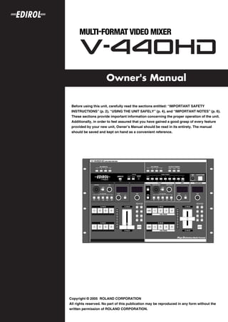
- 1. Owner's Manual 201b Before using this unit, carefully read the sections entitled: “IMPORTANT SAFETY INSTRUCTIONS” (p. 2), “USING THE UNIT SAFELY” (p. 4), and “IMPORTANT NOTES” (p. 6). These sections provide important information concerning the proper operation of the unit. Additionally, in order to feel assured that you have gained a good grasp of every feature provided by your new unit, Owner’s Manual should be read in its entirety. The manual should be saved and kept on hand as a convenient reference. 202 Copyright © 2005 ROLAND CORPORATION All rights reserved. No part of this publication may be reproduced in any form without the written permission of ROLAND CORPORATION.
- 2. WARNING: To reduce the risk of fire or electric shock, do not expose this apparatus to rain or moisture. The lightning flash with arrowhead symbol, within an CAUTION equilateral triangle, is intended to alert the user to the RISK OF ELECTRIC SHOCK DO NOT OPEN presence of uninsulated “dangerous voltage” within the product’s enclosure that may be of sufficient magnitude to ATTENTION: RISQUE DE CHOC ELECTRIQUE NE PAS OUVRIR constitute a risk of electric shock to persons. CAUTION: TO REDUCE THE RISK OF ELECTRIC SHOCK, The exclamation point within an equilateral triangle is DO NOT REMOVE COVER (OR BACK). intended to alert the user to the presence of important NO USER-SERVICEABLE PARTS INSIDE. operating and maintenance (servicing) instructions in the literature accompanying the product. REFER SERVICING TO QUALIFIED SERVICE PERSONNEL. INSTRUCTIONS PERTAINING TO A RISK OF FIRE, ELECTRIC SHOCK, OR INJURY TO PERSONS. IMPORTANT SAFETY INSTRUCTIONS SAVE THESE INSTRUCTIONS WARNING - When using electric products, basic precautions should always be followed, including the following: 1. Read these instructions. 10. Protect the power cord from being walked on or pinched 2. Keep these instructions. particularly at plugs, convenience receptacles, and the 3. Heed all warnings. point where they exit from the apparatus. 4. Follow all instructions. 11. Only use attachments/accessories specified 5. Do not use this apparatus near water. by the manufacturer. 6. Clean only with a dry cloth. 12. Unplug this apparatus during lightning storms or when 7. Do not block any of the ventilation openings. Install in unused for long periods of time. accordance with the manufacturers instructions. 13. Refer all servicing to qualified service personnel. Servicing 8. Do not install near any heat sources such as radiators, is required when the apparatus has been damaged in any heat registers, stoves, or other apparatus (including way, such as power-supply cord or plug is damaged, liquid amplifiers) that produce heat. has been spilled or objects have fallen into the apparatus, 9. Do not defeat the safety purpose of the polarized or the apparatus has been exposed to rain or moisture, does grounding-type plug. A polarized plug has two blades with not operate normally, or has been dropped. one wider than the other. A grounding type plug has two blades and a third grounding prong. The wide blade or the third prong are provided for your safety. If the provided plug does not fit into your outlet, consult an electrician for replacement of the obsolete outlet. For the U.K. WARNING: THIS APPARATUS MUST BE EARTHED IMPORTANT: THE WIRES IN THIS MAINS LEAD ARE COLOURED IN ACCORDANCE WITH THE FOLLOWING CODE. GREEN-AND-YELLOW: EARTH, BLUE: NEUTRAL, BROWN: LIVE As the colours of the wires in the mains lead of this apparatus may not correspond with the coloured markings identifying the terminals in your plug, proceed as follows: The wire which is coloured GREEN-AND-YELLOW must be connected to the terminal in the plug which is marked by the letter E or by the safety earth symbol or coloured GREEN or GREEN-AND-YELLOW. The wire which is coloured BLUE must be connected to the terminal which is marked with the letter N or coloured BLACK. The wire which is coloured BROWN must be connected to the terminal which is marked with the letter L or coloured RED. 2
- 3. For EU Countries This product complies with the requirements of European Directives EMC 89/336/EEC and LVD 73/23/EEC. For the USA FEDERAL COMMUNICATIONS COMMISSION RADIO FREQUENCY INTERFERENCE STATEMENT This equipment has been tested and found to comply with the limits for a Class B digital device, pursuant to Part 15 of the FCC Rules. These limits are designed to provide reasonable protection against harmful interference in a residential installation. This equipment generates, uses, and can radiate radio frequency energy and, if not installed and used in accordance with the instructions, may cause harmful interference to radio communications. However, there is no guarantee that interference will not occur in a particular installation. If this equipment does cause harmful interference to radio or television reception, which can be determined by turning the equipment off and on, the user is encouraged to try to correct the interference by one or more of the following measures: – Reorient or relocate the receiving antenna. – Increase the separation between the equipment and receiver. – Connect the equipment into an outlet on a circuit different from that to which the receiver is connected. – Consult the dealer or an experienced radio/TV technician for help. This device complies with Part 15 of the FCC Rules. Operation is subject to the following two conditions: (1) This device may not cause harmful interference, and (2) This device must accept any interference received, including interference that may cause undesired operation. Unauthorized changes or modification to this system can void the users authority to operate this equipment. This equipment requires shielded interface cables in order to meet FCC class B Limit. For Canada NOTICE This Class B digital apparatus meets all requirements of the Canadian Interference-Causing Equipment Regulations. AVIS Cet appareil numérique de la classe B respecte toutes les exigences du Règlement sur le matériel brouilleur du Canada. 3
- 4. USING THE UNIT SAFELY Used for instructions intended to alert The symbol alerts the user to important instructions the user to the risk of death or severe or warnings.The specific meaning of the symbol is injury should the unit be used determined by the design contained within the improperly. triangle. In the case of the symbol at left, it is used for general cautions, warnings, or alerts to danger. Used for instructions intended to alert the user to the risk of injury or material The symbol alerts the user to items that must never be carried out (are forbidden). The specific thing that damage should the unit be used must not be done is indicated by the design contained improperly. within the circle. In the case of the symbol at left, it * Material damage refers to damage or means that the unit must never be disassembled. other adverse effects caused with The ● symbol alerts the user to things that must be respect to the home and all its carried out. The specific thing that must be done is furnishings, as well to domestic indicated by the design contained within the circle. In animals or pets. the case of the symbol at left, it means that the power- cord plug must be unplugged from the outlet. 001 008e • Before using this unit, make sure to read the • Use only the attached power-supply cord. Also, instructions below, and the Owner’s Manual. the supplied power cord must not be used with any other device. .......................................................................................................... .......................................................................................................... 001-50 009 • Connect mains plug of this model to a mains • Do not excessively twist or bend the power cord, socket outlet with a protective earthing nor place heavy objects on it. Doing so can connection. damage the cord, producing severed elements .......................................................................................................... and short circuits. Damaged cords are fire and shock 002a • Do not open or perform any internal modifica- hazards! tions on the unit. .......................................................................................................... 011 .......................................................................................................... • Do not allow any objects (e.g., flammable 003 material, coins, pins); or liquids of any kind • Do not attempt to repair the unit, or replace parts (water, soft drinks, etc.) to penetrate the unit. within it (except when this manual provides specific instructions directing you to do so). Refer all servicing to your retailer, the nearest Roland Service .......................................................................................................... Center, or an authorized Roland distributor, as listed on 012a the “Information” page. • Immediately turn the power off, remove the .......................................................................................................... power cord from the outlet, and request servicing 004 by your retailer, the nearest Roland Service • Never use or store the unit in places that are: Center, or an authorized Roland distributor, as listed on • Subject to temperature extremes (e.g., direct the “Information” page when: sunlight in an enclosed vehicle, near a heating • The power-supply cord, or the plug has been duct, on top of heat-generating equipment); or damaged; or are • If smoke or unusual odor occurs • Damp (e.g., baths, washrooms, on wet floors); or are • Objects have fallen into, or liquid has been spilled onto • Humid; or are the unit; or • Exposed to rain; or are • The unit has been exposed to rain (or otherwise has • Dusty; or are become wet); or • Subject to high levels of vibration. • The unit does not appear to operate normally or .......................................................................................................... exhibits a marked change in performance. 007 .......................................................................................................... • Make sure you always have the unit placed so it is 014 level and sure to remain stable. Never place it on • Protect the unit from strong impact. stands that could wobble, or on inclined surfaces. (Do not drop it!) .......................................................................................................... 008a .......................................................................................................... • The unit should be connected to a power supply only of the type described in the operating instructions, or as marked on the rear side of unit. .......................................................................................................... 4
- 5. 015 101a • Do not force the unit’s power-supply cord to • The unit should be located so that its location or share an outlet with an unreasonable number of position does not interfere with its proper venti- other devices. Be especially careful when using lation. extension cords—the total power used by all devices you .......................................................................................................... have connected to the extension cord’s outlet must never 102b • Always grasp only the plug on the power-supply exceed the power rating (watts/amperes) for the cord when plugging into, or unplugging from, an extension cord. Excessive loads can cause the insulation outlet or this unit. on the cord to heat up and eventually melt through. .......................................................................................................... .......................................................................................................... 103a 016 • At regular intervals, you should unplug the • Before using the unit in a foreign country, consult power plug and clean it by using a dry cloth to with your retailer, the nearest Roland Service wipe all dust and other accumulations away from Center, or an authorized Roland distributor, as its prongs. Also, disconnect the power plug from the listed on the “Information” page. power outlet whenever the unit is to remain unused for .......................................................................................................... 026 an extended period of time. Any accumulation of dust • Do not put anything that contains water (e.g., between the power plug and the power outlet can result flower vases) on this unit. Also, avoid the use of in poor insulation and lead to fire. insecticides, perfumes, alcohol, nail polish, spray .......................................................................................................... cans, etc., near the unit. Swiftly wipe away any liquid that 104 • Try to prevent cords and cables from becoming spills on the unit using a dry, soft cloth. entangled. Also, all cords and cables should be .......................................................................................................... placed so they are out of the reach of children. .......................................................................................................... 106 • Never climb on top of, nor place heavy objects on the unit. .......................................................................................................... 107b • Never handle the power cord or its plugs with wet hands when plugging into, or unplugging from, an outlet or this unit. .......................................................................................................... 108a • Before moving the unit, disconnect the power plug from the outlet, and pull out all cords from external devices. .......................................................................................................... 109a • Before cleaning the unit, turn off the power and unplug the power cord from the outlet (p. 23). .......................................................................................................... 110a • Whenever you suspect the possibility of lightning in your area, pull the plug on the power cord out of the outlet. .......................................................................................................... 118c • Keep any screws you may remove and the included screws in a safe place out of children’s reach, so there is no chance of them being swallowed accidentally. .......................................................................................................... 5
- 6. IMPORTANT NOTES 291a In addition to the items listed under “USING THE UNIT Maintenance 401a SAFELY” on page 4, please read and observe the • For everyday cleaning wipe the unit with a soft, dry cloth following: or one that has been slightly dampened with water. To remove stubborn dirt, use a cloth impregnated with a Power Supply mild, non-abrasive detergent. Afterwards, be sure to wipe 301 the unit thoroughly with a soft, dry cloth. • Do not connect this unit to same electrical outlet that is 402 being used by an electrical appliance that is controlled by • Never use benzine, thinners, alcohol or solvents of any an inverter (such as a refrigerator, washing machine, kind, to avoid the possibility of discoloration and/or microwave oven, or air conditioner), or that contains a deformation. motor. Depending on the way in which the electrical appliance is used, power supply noise may cause this unit Repairs and Data 452 to malfunction or may produce audible noise. If it is not • Please be aware that all data contained in the unit’s practical to use a separate electrical outlet, connect a memory may be lost when the unit is sent for repairs. power supply noise filter between this unit and the Important data should always be written down on paper electrical outlet. (when possible). During repairs, due care is taken to avoid 307 • Before connecting this unit to other devices, turn off the the loss of data. However, in certain cases (such as when power to all units. This will help prevent malfunctions circuitry related to memory itself is out of order), we and/or damage to TV monitors or other devices. regret that it may not be possible to restore the data, and 308 Roland assumes no liability concerning such loss of data. • Although the LCD and LEDs are switched off when the POWER switch is switched off, this does not mean that the Additional Precautions unit has been completely disconnected from the source of 551 power. If you need to turn off the power completely, first • Please be aware that the contents of memory can be turn off the POWER switch, then unplug the power cord irretrievably lost as a result of a malfunction, or the from the power outlet. For this reason, the outlet into improper operation of the unit. To protect yourself against which you choose to connect the power cord’s plug the risk of loosing important data, we recommend that should be one that is within easy reach and readily acces- you periodically save a backup copy of important data sible. you have stored in the unit’s memory. 552 • Unfortunately, it may be impossible to restore the Placement contents of data that was stored in the unit’s memory once 352a • This device may interfere with radio and television it has been lost. Roland Corporation assumes no liability . 553 reception. Do not use this device in the vicinity of such • Use a reasonable amount of care when using the unit’s receivers. buttons, sliders, or other controls; and when using its jacks 352b • Noise may be produced if wireless communications and connectors. Rough handling can lead to malfunctions. 556 devices, such as cell phones, are operated in the vicinity of • When connecting / disconnecting all cables, grasp the this unit. Such noise could occur when receiving or initi- connector itself—never pull on the cable. This way you ating a call, or while conversing. Should you experience will avoid causing shorts, or damage to the cable’s such problems, you should relocate such wireless devices internal elements. so they are at a greater distance from this unit, or switch 557 them off. • A small amount of heat will radiate from the unit during 355b normal operation. • When moved from one location to another where the 559a temperature and/or humidity is very different, water • When you need to transport the unit, package it in the box droplets (condensation) may form inside the unit. Damage (including padding) that it came in, if possible. Otherwise, or malfunction may result if you attempt to use the unit in you will need to use equivalent packaging materials. add this condition. Therefore, before using the unit, you must • This device allows you to switch images or turn video allow it to stand for several hours, until the condensation effects on/off at high speed. For some people, viewing has completely evaporated. such images can cause headache, nausea, or other Copyright discomfort. Do not use this device to create video that might cause these types of health problems. Roland 851 • Unauthorized recording, distribution, sale, lending, public Corporation will accept no responsibility for any such performance, broadcasting, or the like, in whole or in part, health problems that may occur in yourself or in viewers. of a work (musical composition, video, broadcast, public performance, or the like) whose copyright is held by a third party is prohibited by law. 853 • Do not use this unit for purposes that could infringe on a copyright held by a third party. We assume no responsi- bility whatsoever with regard to any infringements of third-party copyrights arising through your use of this unit. 6
- 7. Contents USING THE UNIT SAFELY ............................4 Using the PANEL PRESET Buttons .........................38 Copying Presets.....................................................38 IMPORTANT NOTES......................................6 Exchanging Presets ...............................................39 Multi-Screen Output ..................................................39 Contents.........................................................7 Connection Instructions for Multi-Screen Output Main Features ................................................8 39 Organization of the V-440HD.....................................8 Making the Multi-Screen Settings ......................40 Multiformat Switcher...................................................9 Advanced Multi-Screen Settings ........................41 HD/RGB Inputs......................................................9 Temporarily Switching Off the Multi-Screen SD Inputs..................................................................9 Function for the Master and Slave Devices.......41 Multiscreen Displays..............................................9 Switching Between NTSC and PAL ...................42 Connection Example ..................................................10 Displaying Test Patterns ......................................42 Live Switching.......................................................10 Reference .................................................... 43 Examples of Devices That Can Be Used ............10 About the HD/RGB IN Connectors (D-Sub)..........43 Before Using the V-440HD..........................11 About the RGB OUT Connectors (D-Sub)...............43 Check the Contents of the Package..........................11 About the TALLY Connectors ..................................44 About the REMOTE Connector ................................44 Names of Things and What They Do .........12 Controlling the V-440HD from an External Device Top Panel .....................................................................12 Via MIDI ......................................................................45 SD Section ..............................................................14 Controlling the V-440HD from an External HD/RGB Section...................................................16 Device Via MIDI....................................................45 Settings Section .....................................................17 MIDI Messages Handled by the V-440HD........46 Rear Panel ....................................................................18 Control Using V-LINK .........................................46 HD Output Section ...............................................19 Instructions for Using V-LINK ...........................46 SD Input/Output Section ....................................19 Installing the Rack Mount Hardware ......................47 HD/RGB Input Section........................................19 Instructions for Attaching the Rack Mount Hardware ...............................................................47 Connections and Settings ..........................20 About Maintenance ....................................................47 Making the Connections............................................20 Daily Maintenance ................................................47 Precautions When Making Settings.........................22 About the Fan ........................................................47 With Rack-Mounting and Other Enclosures.....22 Menu Parameters........................................ 48 Basic Operation...........................................23 Turning On the Power .........................................23 REMOTE Command Reference ................. 56 Turning Off the Power .........................................23 Commands Transmitted from External Devices to Outputting and Stopping the Final Output............23 the V-440HD ................................................................56 Making the Fade-out Settings .............................23 Commands Transmitted from the V-440HD to Making Various Settings ...........................................24 External Devices .........................................................58 Displaying Menus.................................................24 Menu Operations ..................................................25 MIDI implementation................................... 59 Shortcuts to the Menu Parameters .....................25 MIDI IMPLEMENTATION CHART .......................66 Input and Output Settings ..........................26 Block Diagram............................................. 67 Selecting the Output Format.....................................26 Settings and Parameters............................ 68 Making the Output Settings ................................26 HD Size16:9 Output....................................................68 Setting the HD/RGB Input .......................................27 RGB Video Live Output.............................................69 Setting the SD Input ...................................................27 SD Size4:3 Output.......................................................70 HD/RGB Section Operations ......................28 HD-SDI Recording......................................................71 Switching in the HD/RGB Section.....................28 Troubleshooting ......................................... 72 HD/RGB Section P in P Effects ..........................30 HD/RGB Section Key Composite Effects .........32 Memo ........................................................... 74 Menu Settings Memo .................................................74 SD Section Operations ...............................34 Switching in the SD Section.................................34 Index ............................................................ 77 SD Section P in P Effects ......................................35 SD Section Key Composite Effects .....................37 Main specifications..................................... 79 Other Operations.........................................38 7
- 8. Main Features The V-440HD multiformat live switcher is capable of switching between four HD/ RGB input systems and four SD input systems for seamless switching between HD, RGB, and SD inputs. There is no need to obtain separate converters to handle each type of format. Although housed in a compact body, this one device is capable of handling a wide variety of formats. SD VCR SD Video Presenter Plasuma Display Projector HD VCR V-440HD PC About HD An abbreviation for “High Definition,” HD is a generic term for television formats that, in comparison to conventional TV formats, provide higher resolution and an improved angle of view, and deliver a heightened sense of presence by means of large-screen. This is also referred to as HDTV. Although there are a number of different types of HD, which can vary depending on the country where the technology was developed, the V-440HD utilizes the standards recommended in BT.709-3, established by the ITU in February, 1998. About RGB This format, used for output of video images with computers and other digital devices, uses video signals whereby each of three main colors, red (R), green (G), and blue (B), are handled separately. About SD An abbreviation for Standard Definition, this refers to formats currently in general use (such as 480I), as opposed to HD (High Definition). Organization of the V-440HD The V-440HD comprises two main sections, an “HD/RGB section,” which is used to mix all video signals, and an “SD section,” used for managing all SD video. The resulting mixes of composite video and S-video signals from the SD section (PGM output) are sent to the HD/RGB section, where the HD and RGB video are mixed and then output in either HD or RGB format. SD IN 1 SD PGM OUT SD IN 2 SD SD IN 3 Section SD SD IN 4 PGM HD OUT 1 HD OUT 2 HD/RGB IN 1 HD/RGB HD/RGB IN 2 Section RGB OUT 1 RGB OUT 2 HD/RGB IN 3 HD/RGB IN 4 8
- 9. Main Features Multiformat Switcher The V-440HD converts and seamlessly switches signals in HD, RGB, and SD format to the selected final output format. HD Effects • The V-440HD uses a variety of effects, including transitions (effects used when switching video images), P in P, and key composite effects. • Using the V-440HD in combination with an SD video switcher allows you to compose video using up to six different effects simultaneously. Equipped with High-Performance SD-to-HD/RGB Up-Converter The V-440HD features an up-converter that converts SD output to the final output format. This system enables up-conversion of SD video to HD and RGB with superior image quality. HD/RGB Inputs • The HD/RGB inputs provide for the input of four channels of HD or RGB video. • HD inputs are compatible with 1080I as well as the typical 720p format. RGB inputs are compatible with VGA (640 x 480), SXGA (1280 x 1024) formats. • The HD/RGB inputs allow input through BNC and D-Sub connectors • Any HD/RGB input component BNC and D-Sub connectors not in use for input can be used as loop thru outputs. SD Inputs • The V-440HD features four input channels. • SD inputs are compatible with both S-Video and component video. • A preview output is provided for each of the SD inputs 1-4. SD Video Mixer • Capable of switching only SD video input. • PGM output from the SD video mixer can be switched after being input to the multiformat switcher. In addition, SD PGM output can be output as S-Video or composite video. • Effects, including transitions (effects used when switching video images), P in P, and key composite effects can be used. Multiscreen Displays You can use to synchronize multiple V-440HDs easily, and use simple settings to output the signals from one V-440HD to multiscreen displays. This eliminates any need to prepare video for each individual screen. 9
- 10. Main Features Connection Example A variety of video formats can be handled with a single V-440HD, providing great flexibility for various different applications. Live Switching The V-440HD can be used for live switching with video productions that mix material in SD and HD formats. You can freely switch video from HD cameras and SD cameras and use chroma key and luminance key effects with characters displayed by a computer. Stage Camera Projector Preview Monitor PC HD Video Recorder SD Video Deck V-440HD Examples of Devices That Can Be Used Due to its extensive compatibility with HD, RGB, and SD formats, the V-440HD provides a flexible system that can be tailored for any need and budget. HD Video Equipment Plasuma Display SD Video Equipment Preview Monitor V-440HD 10
- 11. Before Using the V-440HD Check the Contents of the Package The V-440HD includes the following accessories. Please take a moment to confirm that all of these items have been included with the V-440HD. If you find that any item is missing, contact your nearest Roland Service Center. V-440HD Power cord * Use only the attached power cord. Also, must not remove the ferrite core from the supplied power code. Owner’s Manual (this volume) 11
- 12. Names of Things and What They Do Top Panel 1 2 3 4 5 6 7 8 9 1. SD IN Buttons 1-4........................................................... (p. 27) 4. HD/RGB IN Buttons 1-4 ..................................................(p. 27) • These indicate the status of the video signals input to each of the • These indicate the status of the video signals input to each of the SD IN inputs (p. 19). HD/RGB IN inputs (p. 19). Button Video Signal Status Button Video Signal Status Lit (Red) Input of composite signal Lit (Red) Input of RGB signal Lit (Green) Input of S-video signal Lit (Green) Input of HD component signal Off No signal input Off No signal input • Holding down the MENU button while pressing an SD IN • Holding down the MENU button while pressing an HD/RGB button displays the SD input menu parameters (p. 27). IN button brings up the HD/RGB input menu parameters (p. 2. MIDI Button...................................................................... (p. 45) 27). This switches the MIDI functions on and off. 5. OUTPUT FORMAT Buttons ............................................(p. 26) The MIDI button is lit when the V-LINK mode is ON. • Press an OUTPUT FORMAT button to select the format for the You can have the status of the V-LINK mode be indicated by the video output from the HD OUT connectors (p. 19) or RGB OUT illumination of the MIDI button. Select “V-LINK Indicator” in “MIDI connectors (p. 19). The selected button lights up. Switch Mode” (p. 55) in the menu. 3. Settings Section ............................................................. (p. 17) Used for making various settings for the V-440HD. Button Output Video Format Output Connectors For descriptions of each of the controllers, refer to Settings Section (p. 1080i 1080/60i (factory default set- HD OUT Connectors 1, 2 ting) 17). 720p 720/60p (factory default set- HD OUT Connectors 1, 2 ting) RGB 1024x768/60 RGB OUT Connectors 1, 2 * You can change the video format selected with each button in the menu (p. 26). 12
- 13. Names of Things and What They Do 6. TIME Knob ...................................................................... (p. 23) Enables setting of the time for the video to fade when the OUTPUT FADE button is pressed. Time can be set from 0.0 to 4.0 seconds. “Channels” and “Buses” * You can adjust the fadeout level by selecting "1. HD/RGB Output" (p. 48) in the menu and setting "12. Output Fade Mode" to • Channel: Each of the V-440HD’s video inputs is called a "Manual." “channel.” The SD and HD/RGB sections feature Channels 1-4, with each channel being independently controlled. 7. OUTPUT FADE Button ................................................... (p. 23) Each “channel” is the equivalent of a “path” for the video Press the OUTPUT FADE button to fade out the video output from the HD OUT connectors or RGB OUT connectors (p. 19). signals. The status of FADE OUT can be determined by viewing the OUTPUT • Bus: On the V-440HD, you can select any combination of FADE button’s light. channels to be controlled as a single group. On the V- 440HD, such a grouping of channels is referred to as a Button Video Output Mode “bus,” and the video for each bus can be selected from the Flashing Fading out channels. The SD section features an A-BUS and B-BUS, Lit Black video output with the C-BUS and D-BUS included in the HD/RGB Off (Normal output) section; in each bus you can control groupings of different input channels. Video A Video B Video C Video D Pressing the OUTPUT FADE button again while the button is lit or flashing causes the video output being faded out to fade back in. 8. SD Section ...................................................................... (p. 14) This section is used for controlling the switching, P in P, key composite, Channel Channel Channel Channel Channel Channel Channel Channel and other functions for the video input to the SD IN inputs. 1 2 3 4 1 2 3 4 For descriptions of each button and knob, refer to SD Section (p. 14). 9. HD/RGB Section............................................................. (p. 16) This section is used for controlling the switching, P in P, key composite, A-BUS B-BUS and other functions for the video input to the HD/RGB IN inputs. Screen selected form Channel 1-4 Screen selected form Channel 1-4 For descriptions of each button and knob, refer to HD/RGB Section (p. 16). Mixer Switch / Composite A-Bus to B-Bus Final Output (PGM) 13
- 14. Names of Things and What They Do SD Section This section is used for controlling the switching, P in P, key composite, 4. SIZE Knob (SD) ............................................................... (p. 36) and other functions for the video input to the SD IN inputs. This adjusts the size of the small screen when the P in P effect is used in the SD section. 1 2 3 4 5 6 7 8 9 5. LEVEL Knob (SD) ............................................................(p. 37) This adjusts the key level when key composite effects are used in the SD section. 6. LEVEL Display (SD) ........................................................(p. 37) This indicates the value of the key level set with the (5.) LEVEL knob (SD). 7. KEY ON Button (SD) ....................................................... (p. 37) Pressing the KEY ON Button (SD) causes the key composite effect to be applied in the SD section. 8. TIME Display (SD) ........................................................... (p. 34) This indicates the transition time used to switch between the A-BUS and B-BUS when the (14.) AUTO button (SD) is pressed. The time is indicated in seconds. 9. TIME Knob (SD) ...............................................................(p. 34) This sets the transition time used to switch between the A-BUS and B- BUS when the (14.) AUTO button (SD) is pressed. The set time is indicated in the TIME display. The time can be set to any value from 0.0 to 4.0. 10. A-BUS Channel Buttons (SD) 1-4 .................................. (p. 35) 10 11 12 13 14 15 These buttons are used to select the video signals to be input to the A- BUS, from the video input to the SD IN connectors 1-4. 1. POSITION Joystick (SD) ................................................ (p. 36) This adjusts the positioning of the small screen when the P in P effect is Button V-440HD Status used in the SD section. Lit (Yellow) Channel is selected The POSITION joystick (SD) can be used only when the LOCK button to Lit (Green) Channel is selected (not displayed) the right of the joystick is pressed to release the lock. Off Channel selection is cancelled 2. LOCK Button (SD) .......................................................... (p. 36) Flashing (Yellow or Green) P in P or key composite is in use When the LOCK button (SD) is lit, the P in P position cannot be changed with the POSITION joystick (SD) to the left of the button. 11. B-BUS Channel Buttons (SD) 1-4 .................................. (p. 35) Pressing the LOCK button (SD) so its light is turned off enables operation These buttons are used to select the video signals to be input to the B- with the POSITION joystick (SD). BUS, from the video input to the SD IN connectors 1-4. 3. P in P PATTERN Buttons (SD) 1-5................................ (p. 35) Pressing the P in P PATTERN 1-5 buttons (SD) applies the P in P effect in Button V-440HD Status the SD section. Lit (Yellow) Channel is selected When the P in P effect is applied, the selected P in P PATTERN button Lit (Green) Channel is selected (not displayed) (SD) lights up. Off Channel selection is cancelled Flashing (Yellow or Green) P in P or key composite is in use Button Sub-Screen Position (Factory Setting) Upper left 12. TRANSITION Indicators (SD) .........................................(p. 34) 1 These indicate the position of the video fader. Upper right 2 When the AUTO button (SD) is in use, these indicate the ratio of video Lower right being switched in the SD section. The portion of A-BUS video in the mix 3 increases as the position of the indicator that lights within the Lower left TRANSITION indicators (SD) gets closer to the A-BUS, while the relative 4 portion of B-BUS video decreases correspondingly. Center 5 14
- 15. Names of Things and What They Do 13. Video Fader (SD) ............................................................ (p. 34) Moving the video fader up or down switches between the SD section A- BUS and B-BUS. Tilt the fader shown in the figure up to switch to the A-BUS; tilt the fader down to switch to the B-BUS. The video switches using the effect selected with the (15.) TRANSITION buttons (SD). 14. AUTO Button (SD).......................................................... (p. 34) When the AUTO button (SD) is pressed, the SD section video switches over the time indicated in the TIME display (SD). The video switches using the effect selected with the (15.) TRANSITION buttons (SD). 15. TRANSITION Buttons (SD) ............................................. (p. 34) These are used to select the effect applied when switching the SD section video with the video fader (SD) or the AUTO button (SD). Button Function Description CUT Cut The SD video switches when the SD video fader reaches the half- way point. MIX Dissolve The SD video is mixed as it gradu- ally switches according to the an- gle of the SD video fader. WIPE Wipe switching The SD video switches with a PATTERN wipe effect, with the wipe corre- 1-6 sponding to the angle of the SD fader. 15
- 16. Names of Things and What They Do HD/RGB Section This section is used for controlling the switching, P in P, key composite, 5. P in P PATTERN Buttons (HD/RGB) 1-5 .......................(p. 30) and other functions for the video input to the HD/RGB inputs. Pressing the P in P PATTERN 1-5 buttons (HD/RGB) applies the P in P effect in the HD/RGB section. When the P in P effect is applied, the selected P in P PATTERN button 1 2 3 4 5 6 78 9 10 11 (HD/RGB) lights up. Button Sub-Screen Position (Factory Setting) Upper left 1 Upper right 2 Lower right 3 Lower left 4 Center 5 6. SIZE/ZOOM Knob (HD/RGB) ..........................................(p. 31) This adjusts the size of the small screen when the P in P effect is used in the HD/RGB section. 7. LEVEL Knob (HD/RGB) ..................................................(p. 33) This adjusts the key level when key composite effects are used in the HD/RGB section. 8. LEVEL Display (HD/RGB)............................................... (p. 33) This indicates the value of the key level set with the (7.) LEVEL knob (HD/RGB). 12 13 14 15 16 17 9. KEY ON Button (HD/RGB).............................................. (p. 32) 1. P in P Button (HD/RGB) ................................................. (p. 31) Pressing the KEY ON Button (HD/RGB) causes the key composite effect When this button is lit, the position of the subscreen when the P in P effect is to be applied in the HD/RGB section. used in the HD/RGB section can be set with the POSITION joystick (HD/ 10. TIME Display (HD/RGB) ..................................................(p. 28) RGB), while the subscreen size can be set with the SIZE/ZOOM knob (HD/ This indicates the transition time used to switch between the C-BUS and RGB). D-BUS when the (16.) AUTO button (HD/RGB) is pressed. The time is 2. PAN/ZOOM Button (HD/RGB) ....................................... (p. 31) indicated in seconds. When using the P in P effect in the HD/RGB section, the crop position and zoom ratio of the small screen can be set with the POSITION/PAN 11. TIME Knob (HD/RGB) .....................................................(p. 28) joystick (HD/RGB) and SIZE/ZOOM knob (HD/RGB) knob when this This sets the transition time used to switch between the C-BUS and D- button is lit. BUS when the (16.) AUTO button (HD/RGB) is pressed. The set time is indicated in the TIME display. The time can be set to any value from 0.0 3. POSITION/PAN Joystick (HD/RGB) .............................. (p. 31) to 4.0. This adjusts the position of, and zoom for the small screen when the P in P effect is used in the HD/RGB section. 12. C-BUS Channel Buttons (HD/RGB) A/B, 1-4................. (p. 29) The POSITION/PAN joystick (HD/RGB) can be used only when the These buttons are used to select the video signals to be input to the C- LOCK button to the right of the POSITION/PAN joystick (HD/RGB) is BUS, either from the video input to the HD/RGB IN connectors 1-4 or the pressed to release the lock. final output from the SD section (SD PGM video). 4. LOCK Button (HD/RGB) ................................................. (p. 31) When the LOCK button (HD/RGB) is lit, neither the position nor panning of Button V-440HD Status the P in P subscreen be changed with the POSITION/PAN joystick (HD/RGB). Lit (Yellow) Channel is selected Pressing the LOCK button (HD/RGB) so enables operation with the Lit (Green) Channel is selected (not displayed) POSITION/PAN joystick (HD/RGB). Off Channel selection is cancelled Flashing (Yellow or Green) P in P or key composite is in use 16
- 17. Names of Things and What They Do 13. D-BUS Channel Buttons (HD/RGB) A/B, 1-4................ (p. 29) These buttons are used to select the video signals to be input to the D- BUS, either from the video input to the HD/RGB IN connectors 1-4 or the Settings Section final output from the SD section (SD PGM video). 1 2 3 4 5 Button V-440HD Status Lit (Yellow) Channel is selected Lit (Green) Channel is selected (not displayed) Off Channel selection is cancelled Flashing (Yellow or Green) P in P or key composite is in use 1. MENU Button ...................................................................(p. 24) 14. TRANSITION Indicators (HD/RGB) ............................... (p. 28) Pressing the MENU button displays the menu in the video monitor These indicate the position of the video fader. connected to the SD PREVIEW OUT connector. When the AUTO button (HD/RGB) is in use, these indicate the ratio of Rotate the VALUE knob to select the parameter to be set, then press the video being switched in the HD/RGB section. The portion of C-BUS ENTER button to enter the selection. video in the mix increases as the position of the indicator that lights Pressing the MENU button while the menu is displayed closes the menu. within the TRANSITION indicators (HD/RGB) gets closer to the C-BUS, When the menu is appeared, the MENU button Flashing. When the while the relative portion of D-BUS video decreases correspondingly. menu is disappeared, the MENU button Off. 15. Video Fader (HD/RGB) ................................................... (p. 28) 2. ENTER Button ................................................................. (p. 24) Moving the video fader up or down switches between the C-BUS and D- This is used to confirm a menu choice. The button flashes while the menu BUS of the HD/RGB section. is displayed. Tilt the fader shown in the figure up to switch to the C-BUS; tilt the fader 3. VALUE Knob ................................................................... (p. 24) down to switch to the D-BUS. The video switches using the effect selected This is used to select parameters from the menu. with the (17.) TRANSITION buttons (HD/RGB). 4. SHIFT Button................................................................... (p. 38) 16. AUTO Button (HD/RGB) ................................................. (p. 28) Pressing the SHIFT button so it’s lit enables selection of PANEL PRESET When the AUTO (HD/RGB) button is pressed, the HD/RGB section 9-15 using the PANEL PRESET buttons (1-8). video switches over the time indicated in the TIME display (HD/RGB). The video switches using the effect selected with the (17.) TRANSITION 5. PANEL PRESET Buttons 1-8 ......................................... (p. 38) buttons (HD/RGB). You can store up to 15 separate configurations of parameter settings set in each of the top sections. 17. TRANSITION Buttons (HD/RGB) ................................... (p. 28) You can call up the saved settings by pressing the PANEL PRESET These are used to select the effect applied when switching the HD/RGB buttons. section video with the video fader (HD/RGB) or the AUTO button (HD/ PANEL PRESET 9-15 and FACTORY RESET can be selected when the RGB). SHIFT button is lit. Button Function Description Button V-440HD Function CUT Cut The HD/RGB video switches when the HD/RGB video fader Lit (Green) Selects PANEL PRESET 1-8 reaches the half-way point. Lit (Red) Selects PANEL PRESET 9-15, FAC- MIX Dissolve The HD/RGB video is mixed as it TORY RESET gradually switches according to Off No PANEL PRESET selected the angle of the HD/RGB video fader. WIPE Wipe switching The HD/RGB video switches with PATTERN a wipe effect, with the wipe corre- 1-6 sponding to the angle of the HD/ RGB fader. 17
- 18. Names of Things and What They Do Rear Panel 1 2 3 4 5 6 7 8 9 10 11 12 1. POWER Switch ............................................................... (p. 23) 10. REMOTE Connector ...................................................... (p. 44) This switches the V-440HD’s power on and off. Use this connector when using serial control from computers or other 945 need to turn off the power completely, first turn off the POWER If you external devices. switch, then unplug the power cord from the power outlet. Refer to Refer to the chart of serial signals on p. 44. Turning Off the Power (p. 23). 11. Ground terminal 2. AC Inlet ........................................................................... (p. 20) 927 Depending on the circumstances of a particular setup, you may Connect the power cord included with the V-440HD here. experience a discomforting sensation, or perceive that the surface feels 3. Exhaust Vent .................................................................. (p. 22) gritty to the touch when you touch this device, microphones connected to Heat generated by the V-440HD is expelled here. it, or the metal portions of other objects, such as guitars. This is due to an infinitesimal electrical charge, which is absolutely harmless. However, if you are concerned about this, connect the ground terminal (see figure) Allowing this section of the panel to be blocked may, due to the with an external ground. When the unit is grounded, a slight hum may buildup of excess heat, result in damage to the V-440HD. occur, depending on the particulars of your installation. If you are unsure of the connection method, contact the nearest Roland Service Center, or 4. HD/RGB Output Section ................................................. (p. 19) an authorized Roland distributor, as listed on the “Information” page. Video in HD or RGB format is output here. For descriptions of each Unsuitable places for connection connector, refer to p. 19. • Water pipes (may result in shock or electrocution) 5. HD/RGB Input Section ................................................... (p. 19) • Gas pipes (may result in fire or explosion) Four channels of HD or RGB video can be input using the BNC or D-sub • Telephone-line ground or lightning rod (may be dangerous in connectors. BNC and D-sub terminals not used for signal input can be used as THRU outs. For descriptions of each connector, refer to p. 19. the event of lightning) 988 6. SD Input/Output Section ............................................... (p. 19) 12. SECURITY Slot ( ) Four channels of SD video can be input using the composite video or S- video connectors. For descriptions of each connector, refer to p. 19. http://www.kensington.com/ 7. TALLY Terminals (HD, SD)............................................ (p. 44) TALLY signals are output here. When a television monitor equipped with a TALLY terminal is connected to the V-440HD, the V-440HD can then be used to activate the television monitor's TALLY lamp. Tally signals from the HD/RGB section are output from the TALLY HD terminal; tally signals from the SD section are output from the TALLY SD terminal. For descriptions of each terminals, refer to p. 44. 8. MIDI OUT/THRU ............................................................. (p. 45) Use this connector to connect the V-440HD to an external MIDI device and transmit MIDI messages to the other MIDI device. Use a MIDI cable (sold separately) to connect the devices. You can also use this connector as a THRU output for MIDI signals received at the MIDI IN connector. 9. MIDI IN Connector.......................................................... (p. 45) Use this connector to connect the V-440HD to an external MIDI device About the Preview Screen and receive MIDI messages from the other MIDI device. Use a MIDI cable (sold separately) to connect the devices. The V-440HD's "Preview OUT" outputs video from the bus not being used to output from PGM OUT. 18
- 19. Names of Things and What They Do 4. SD S-VIDEO IN 1-4 Connectors .......................... (p. 20, p. 27) These are connectors for input of S-Video to SD buses 1-4. HD Output Section Video devices equipped with an S-Video output connector can be connected here.As initially set at the factory, when video is 1 2 3 4 simultaneously being input to the SD COMPOSITE IN connector for the same channel, the video input to the SD S-VIDEO IN connector is given priority. 5. SD COMPOSITE IN 1-4 Connectors (Analog) .... (p. 20, p. 27) These are connectors for input of composite video to SD buses 1-4. Video devices equipped with a composite video output connector can be connected here. As initially set at the factory, when video is simultaneously being input to the SD S-VIDEO IN connector for the same channel, the video input to the SD S-VIDEO IN connector is given priority. * You can set the V-440HD so that the SD COMPOSITE IN connectors the SD S-VIDEO IN connectors. To make this setting, go to "7. SD Input" (p. 51) - "1. SD Input Select" in the menu, then select "Composite." 1. RGB PREVIEW Connector (Analog RGB) .................... (p. 20) 6. SD MONITOR OUT Output 1-4 Connectors (Analog Composite Video)...(p. 20) The HD/RGB bus preview screen is output in RGB (analog/D-Sub) from These BNC connectors output video from the SD S-VIDEO IN connectors or SD this connector. COMPOSITE IN connectors as composite video. When the V-440HD is connected to a video monitor equipped with composite * The video in the HD/RGB Preview screen is displayed with the P in P video input connectors, you can monitor the video of each channel. effect (p. 30) and other such effects applied. 2. HD PREVIEW Connectors (Analog Component)......... (p. 20) This is a BNC connector for outputting the HD/RGB bus preview screen HD/RGB Input Section as analog component video. * The video in the HD/RGB Preview screen is displayed with the P in P effect (p. 30) and other such effects applied. 3. HD OUT 1, 2 Connectors (Analog Component)........... (p. 20) These are BNC connectors for outputting the video combined on the 1 HD/RGB bus as analog component video. 4. RGB OUT 1, 2 Connectors (Analog RGB) .......... (p. 20, p. 43) The composite video from the HD/RGB bus is output as RGB signals 2 from this connector. 3 SD Input/Output Section 1. HD/RGB IN 1-4 Connectors (Analog Component/RGB) .. (p. 20) 1 2 3 4 5 6 These are BNC connectors capable of being used for input of analog component signals or RGB signals. If not inputting video, connectors to which no video is being input can be used as loop thru outputs for video input via the HD/RGB IN 1-4 connectors (analog RGB). * Video cannot be input via both the HD/RGB IN (BNC) connectors and IN (D-Sub) connectors simultaneously. Inputting video simultaneously in this manner may result in disruption of the video images. 2. HD/RGB 75 TERMINATOR 1-4 Switches ............................(p. 21) Switch to ON if no cables are connected to either the HD/RGB IN (BNC) 1. SD PGM OUT COMPOSITE Connector (Analog) ......... (p. 20) connectors or the HD/RGB IN (D-Sub) connector. This connector outputs composite effects from the SD section as Switch to OFF if using these connectors as loop thru connectors. composite video signals. Video monitors equipped with a composite video input connector can be connected here. 3. HD/RGB IN 1-4 Connectors (RGB/Analog Component) .. (p. 20, p. 43) These are D-Sub connectors capable of being used for input of analog 2. SD PGM OUT S-VIDEO Connector ............................... (p. 20) component signals or RGB signals. This Connector outputs composite effects from the SD bus as S-video If not inputting video, connectors to which no video is being input can be signals. Video monitors equipped with an S-Video input connector can be used as loop thru outputs for video input via the HD/RGB IN 1-4 connected here. connectors (analog component). 3. SD PREVIEW OUT Connector ............................. (p. 20, p. 24) * Video cannot be input via both the HD/RGB IN (BNC) connectors and The preview screen from the SD Section is output from this connector. IN (D-Sub) connectors simultaneously. Inputting video simultaneously The menu (p. 24) is also displayed. in this manner may result in disruption of the video images. * The video in the SD Preview screen is displayed without the P in P effect (p. 35) and other such effects applied. 19