
Recommandé
Contenu connexe
Tendances
Tendances (20)
Similaire à Urhe cf y-un50_00
Similaire à Urhe cf y-un50_00 (20)
Plus de Oliverh Kalprit
Plus de Oliverh Kalprit (19)
Dernier
Dernier (20)
Urhe cf y-un50_00
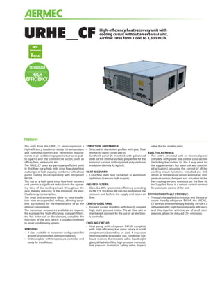
- 1. High-efficiency heat recovery unit with cooling circuit without an external unit. Air flow rates from 1,000 to 3,300 m3/h.URHE_CF Features The units from the URHE_CF series represent a high-efficiency solution to satisfy the temperature and humidity comfort and ventilation require- ments in air conditioning systems that serve pub- lic spaces and the commercial sector, such as offices, bars, restaurants, etc. The URHE_CF units are particularly efficient units in that they use a high yield cross flow plate heat exchanger of high capacity combined with a heat pump cooling circuit operating with refrigerant R410A. The use of a high yield cross flow heat recovery unit permits a significant reduction in the operat- ing time of the cooling circuit throughout the year, thereby reducing to the minimum the elec- trical energy consumption. The small unit dimensions allow for easy installa- tion even in suspended ceilings, allowing excel- lent accessibility for the maintenance of all the internal components. The numerous accessories available on request, for example the high-efficiency compact filters, the hot water coil or the silencers, complete the functions of the unit, which is usually combined to an air conditioning system. VERSIONS • 4 sizes available in horizontal configuration for ground or suspended ceiling installation. • Unit complete with temperature controller and ready for installation. STRUCTURE AND PANELS: • Structure in aluminium profiles with glass fibre reinforced nylon corner pieces. • Sandwich panel 25 mm thick with galvanised steel for the internal surface, prepainted for the external surface with injected polyurethane insulation (density 42 kg/m3). HEAT RECOVERY: • Cross flow plate heat exchanger in aluminium optimised to ensure high outputs. PLEATED FILTERS: • Class G4, 80% gravimetric efficiency according to EN 779, thickness 48 mm, located before the recovery unit both in the supply and return air flow. CENTRIFUGAL FANS: • Forward curved impellers with directly coupled high static pressure motor. The air flow rate is maintained constant by the use of an electron- ic controller. COOLING CIRCUIT: • Heat pump with refrigerant R410A, complete with high-efficiency low noise rotary or scroll compressors (depending on size), 4 way cycle reversing valve, evaporator coil, condenser coil, liquid receiver, thermostatic valve, liquid sight glass, dehydrator filter, high pressure manostat, low pressure manostat, safety valve, bypass valve (for the smaller sizes). ELECTRICAL PANEL: • The unit is provided with an electrical panel complete with power and control cross-section (including the control for the 3 way valve for the supplementary hot water coil and associat- ed actuators), ensuring the control of all the cooling circuit functions. Included are: NTC return air temperature sensor, external air tem- perature sensor, dampers and actuators in the free-cooling version, manostat on the flow fil- ter. Supplied loose is a remote control terminal for automatic control of the unit. ENVIRONMENTALLY FRIENDLY: • Through the applied technology and the use of ozone friendly refrigerant R410A, the URCHE_ CF series is environmentally friendly. R410A is a refrigerant with high thermodynamic efficiency and this, together with the use of scroll com- pressors, allows for reduced CO2 emissions. TECHNOLOGY HIGH EFFICIENCY
- 2. Accessories • MBCH hot water coil module • MBCX electric coil module • FCT high-efficiency compact filters F7 • BIT base for floor mounting • BIM base for floor mounting for additional modules • TPE roof for external installation • TPM roof for external installation of addition- al modules • FCH free-cooling kit • RS485 board RS485 • MSS n° 1 silencer splitter module • TPMSS roof for silencer splitter module • FGE circular flanges Standard inverter for fans to maintain constant air flow rate High-efficiency heat pump cooling circuit Unit fitted with thermoregulation with unit mounted electrical panel Filters class G4 EN779 in supply and return High-efficiency plate heat exchanger Remote panel (standard) URHE_CF 10 15 25 33 MBCH MBCH1 MBCH1 MBCH1 MBCH2 MBCX MBCX1 MBCX2 MBCX3 MBCX4 FCT FCT1 FCT1 FCT2 FCT3 BIT BIT1 BIT1 BIT2 BIT3 BIM BIM1 BIM1 BIM1 BIM1 TPE TPE1 TPE1 TPE2 TPE3 TPM TPM1 TPM1 TPM1 TPM2 FCH FCH1 FCH1 FCH2 FCH2 RS485 RS485 RS485 RS485 RS485 MSS MSS1 MSS1 MSS2 MSS2 TPMSS TPMSS1 TPMSS1 TPMSS1 TPMSS2 FGE FGE1 FGE1 FGE1 FGE1
- 3. Technical data URHE_CF 10 15 25 33 Maximum air flow and recovery flow rate 1000 1500 2500 3300 Air flow minimum 800 1100 2000 2500 Available flow and return static pressure (1) (Pa) 320 245 140 220 Heating capacity recovered (2) (kW) 7 10 15.3 19.6 Cooling capacity recovered (3) (kW) 2.2 3.2 4.5 5.8 Total heating capacity (recovery unit + compressor) (2) (kW) 10.9 14.2 24.8 33.1 Total cooling capacity (recovery unit + compressor) (3) (kW) 6.6 8.7 13.8 19.8 Available heating capacity (2) (kW) 2.8 2.9 3.9 7 Available cooling capacity (3) (kW) 1.8 3.1 3.3 5.4 RECOVERY UNIT Efficiency in winter condition (%) 82 80 73 71 Efficiency in summer condition (%) 82 80 68 65 FANS Number of fans 2 2 2 2 1 fan maximum input power (kW) 0.42 0.46 1.1 1.1 1 fan maximum input current (A) 3.10 3.10 5.3 5.3 Heating total input power (2) kW 2.2 2.4 4.2 4.9 Cooling total input power (3) kW 2.6 2.9 5.1 6.5 Protection rating IP 55 55 55 55 Sound power level dB(A) 66 69 72 75 FILTERS (standard) EN779 Classification G4 G4 G4 G4 Gravimetric efficiency (%) 90 90 90 90 EN779 Classification (accessory filters) F7 F7 F7 F7 Additional pressure drop for filters F7 (accessory) Δ (Pa) 35 59 58 63 COOLING CIRCUIT (COMPRESSOR) Refrigerant R410A R410A R410A R410A Compressor maximum current input (A) 10 11 7 10.3 CONDENSATE DRAINTRAY Condensate drain tray discharge diameter (in) 1” 1” 1” 1” MBCH - HOT WATER COIL (accessory) Rows (n) 2 2 2 2 Air side pressure drop (nominal flow rate) (Pa) 7 18 37 37 Heating capacity (4) (kW) 7.7 10.3 15.6 19.7 Heating capacity (5) (kW) 2.6 4 6.5 7.6 Water flow rate at nominal conditions (4) (l/h) 673 906 1363 1725 Water side pressure drop (nominal conditions) (4) (kPa) 11 8 18 32 Water flow rate at nominal conditions (5) (l/h) 446 700 1118 1311 Water side pressure drop (nominal conditions) (5) (kPa) 3 6 14 22 Water coil manifold diameter (in) 3/4” 3/4” 3/4” 3/4” MBCX - Electric heating coil (accessory) Power supply 400V/3/50Hz (separate power supply from the unit) Heating capacity (kW) 5 7.5 12.5 16.5 Air side pressure drops (nominal flow rate) (Pa) 10 10 10 10 Stages (n) 1 1 1 1 Electric coil current input (A) 7.6 11.4 19 25.1 (1) Fan power supply: 230V; nominal air flow rate; without accessories; Cooling (2) Operating conditions: return air 26°C 50%, external air 34°C 50%; Heating (3) Operating conditions: return air 20°C 50%, external air -5°C 80%; (4) This value offers an indication of the capacity produced by the unit net of the capacity used to bring the external air conditions to neutral values (specifically, 20°C with 50% UR in winter and 26°C with 50% UR in summer) (5) At 1 m distance in free field with ducted connections. (6) Inlet/outlet water temperature 70/60°C. Compressor operating. Operating conditions: return air 20°C 50%, external air -5°C 80%; (7) Inlet/outlet water temperature 45/40°C. Compressor operating. Operating conditions: return air 20°C 50%, external air -5°C 80%; (1) Fan power supply: 230V; nominal air flow rate; without accessories; (2) Fresh air flow rate equal to exhaust air flow rate: incoming external air temperature -5°C, 80% UR; Room temperature 20°C, 50% UR (3) Performance referring to: fresh air flow rate equal to exhaust air flow rate; incoming external air temperature 34°C, 50% UR; room temperature 26°C, 50% UR. (4) Performance referred to: inlet/outlet water temperature 70/60°C; at conditions 2) with compressor operating (5) Performance referred to: inlet/outlet water temperature 45/40°C at conditions 2) with compressor operating Sound power level of the flow fan not ducted with useful static pressure equivalent to 0 Pa.
- 4. URHE-CF_Y_UN50_00 Dimensions (mm) URHE_CF 10 15 25 33 Height A (mm) 580 580 580 580 Width B (mm) 1640 1640 1640 1970 Depth C (mm) 1500 1500 1990 2310 Weight (kg) 300 310 373 410 A B C Aermec S.p.A. Via Roma, 996 - 37040 Bevilacqua (VR) - Italia Tel. 0442633111 - Telefax 044293577 www.aermec.com All specifications are subject to change without prior notice. Although every effort has been made to ensure accuracy, Aermec does not assume responsibility or liability for eventual errors or omissions.