Back on Track: Navigating the Return to Work after Parental Leave
History of-angles-measurements
1. WSHS 1 – History of Technology
David A. Wallis
WSHS1.2 History of Angle Measurement
From Pharaohs to Geoinformatics
FIG Working Week 2005 and GSDI-8
Cairo, Egypt April 16-21, 2005
1/17
History of Angle Measurement
David A. WALLIS, United Kingdom
Key words: History, Egyptians, Theodolite, Ramsden, Dividing.
SUMMARY
The paper covers the period from the time when angles were measured using rather primitive
methods and charts the requirement for increasing accuracy, which was driven by scientist
and instrument makers, employing their skills in devising ways of achieving the best possible
measurements.
In particular the paper summarises the development of angle reading systems over the last
century, making it possible to reliably measure angles to within a fraction of a second of arc,
both optically and electronically and traces the thought behind each of the advances in
instrument design.
2. WSHS 1 – History of Technology
David A. Wallis
WSHS1.2 History of Angle Measurement
From Pharaohs to Geoinformatics
FIG Working Week 2005 and GSDI-8
Cairo, Egypt April 16-21, 2005
2/17
History of Angle Measurement
David A. WALLIS, United Kingdom
1. EARLIEST TIMES
In 1936 a clay tablet was excavated at Shush (Khuzistan region of Iran) some 350km from the
ancient city of Babylon on which was inscribed a script that was only translated as late as
1950, The text provided confirmation that the Babylonians' measured angles using the figure
of 360 to form a circle The inscription on the tablet shows the ratio of a perimeter of a regular
hexagon to the circumscribed circle i.e.
Six sides of a hexagon times their base of 60 = 360.
Clay Tablet from Shush, depicting mathematical symbols
The Babylonians' knew that the perimeter of a hexagon was exactly equal to six times the
radius of a circumscribed circle, a fact that was evidently the reason why they chose to divide
the circle into 360 parts. The tablet gave Pi = 25/8 = 3.125
This proved that the Babylonians used the sexagesimal system based on 60 rather than the
centesimal system based on units of 10.
The history of the mathematical measurement of angles, possibly dates back to 1500BC in
Egypt, where measurements were taken of the Sun's shadow against graduations marked on
stone tables, examples of which can be seen in the Egyptian Museum in Berlin. The shadow
was cast but a vertical rod (Gnomon) along the length of the markings on a stone tablet,
enabling time and seasons to be measured with some degree of accuracy.
3. WSHS 1 – History of Technology
David A. Wallis
WSHS1.2 History of Angle Measurement
From Pharaohs to Geoinformatics
FIG Working Week 2005 and GSDI-8
Cairo, Egypt April 16-21, 2005
3/17
The first known instrument for measuring angle was possibly the Egyptian Groma an
instrument used in the construction of massive works such as the pyramids. The Groma
consisted of 4 stones hanging by cords from sticks set at right angles; measurements were
then taken by the visual alignment of two of the suspended cords and the point to be set out. It
was rather limited in is application due to the fact that it was only able to be used on fairly flat
terrain and its accuracy limited by distance.
Model of Egyptian Groma
The Groma continued to be the instrument used for setting out right angles for many
thousands of years, the Roman's in their construction works, in particular roads, which were
always set out in straight lines for which the Groma was ideally suited. There is a carving on a
tomb near Turin dating from the first century AD, which depicts such an instrument. The
name on the tomb is that of Lucius Aebutius Faustus who was said to be an "Agrimeter" an
early term for Land Surveyor.
When Pompeii was excavated in 1912 versions of the Groma were discovered, these being
constructed from an iron support with plumb bob made from bronze. This type of crude
instrument for setting out right angles has perpetuated to the present day, with the Cross-Staff
Head and its successor the Optical Square.
Possibly the first instrument that could be called as such was the Dioptra (The Greek word
meaning instrument to see through), which possibly dates from about 150BC. Heron of
4. WSHS 1 – History of Technology
David A. Wallis
WSHS1.2 History of Angle Measurement
From Pharaohs to Geoinformatics
FIG Working Week 2005 and GSDI-8
Cairo, Egypt April 16-21, 2005
4/17
Alexandra (10-70AD) described this instrument and from his description one can say it was
the forerunner of the Theodolite.
Model of Dioptra
The Dioptra described by Heron was an instrument consisting of a circular metal plate, which
could be rotated horizontally through 360 degrees by a toothed gear and another plate that
could be tilted in the vertical plane, again by a worm drive. To these plates could be attached
a levelling device, consisting of two interconnected tubes containing water, the level line
being the alignment of the two menisci of the liquid in the upper parts of the tubes. The
Dioptra had a large horizontal circular plate, which was marked out in angles, these could be
aligned with a rotatable metal straightedge to which was fitted with a pair of open sights the
complete instrument was mounted on a heavy wooden stand.
Claudius Ptolemy the Greek astronomer and geographer (85-165AD) made many
astronomical observations in Alexandria, some of which were described as being made with
an instrument called a Triquetrum, which means in Greek "Three Legged" It was a sighting
device with three hinged sections, one section was planted in the ground while the other two
could be rotated to form an isosceles triangle, together with the fixed vertical rod. The rod,
which was directly hinged to the vertical rod, carried two sighting devices or pinholes through
which one could sight the stars and planets. Zenith angles were measured from lines marked
on the third rod. In more modern times, this type of instrument was employed by the military
for some aspects of field surveys.
The first hand held navigation instrument designed to measure angles of any magnitude was
the Astrolabe used by the navigators of the Middle East in their quest to navigate the oceans.
These sophisticated instruments were primarily designed for taking bearings to the stars and
planets to determine position at sea as well as an aid to mapping the land and the shoreline. It
could also be applied to the setting out of civil works
5. WSHS 1 – History of Technology
David A. Wallis
WSHS1.2 History of Angle Measurement
From Pharaohs to Geoinformatics
FIG Working Week 2005 and GSDI-8
Cairo, Egypt April 16-21, 2005
5/17
Early Spanish Astrolabe
The principles of the Astrolabe were known before 150 BC. But recognisable instruments
date from about 400AD. They were highly developed in the Moorish world by 800AD. It was
introduced into Europe from Islamic Spain (Andalusia) in the early part of the 12th century. It
was the most popular astronomical instrument until about 1650 when more specialised and
accurate instruments such as the Sextant replaced it.
As instruments improved, a need was found for reading circles more accurately. Observations
and reading graduations by the unaided eye could be expected to no better than 10 or more
minutes of arc.
The first approach to reading subdivisions is uncertain. Some references give credit to
Peurbach and Regiomontanus of the 15th
century or Richard Chanzler in the 16th
, yet others
put forward that attempts were made in the 14th
century to read angles more accurately.
The earliest attempts at subdivisions were akin to the modern diagonal scale and its
introduction is often credited to Levi Ben Gershon. Originally the idea was almost certainly
one applied to straight scales where it is simple to apply yet accurate.
6. WSHS 1 – History of Technology
David A. Wallis
WSHS1.2 History of Angle Measurement
From Pharaohs to Geoinformatics
FIG Working Week 2005 and GSDI-8
Cairo, Egypt April 16-21, 2005
6/17
2. THE THEODOLITE
The first mention of an instrument called a Theodolite was in 1571 by Leonard Digges in his
book "Pantometria" in which he describes an instrument called a "Theodolitus” In principal
the instrument had a graduated horizontal circle mounted on a vertical column to which was
fixed a graduated vertical semicircle. Angles were taken via a pair of sights mounted of a
rotating ruler with a reading index.
Drawing of Digges Theolitus
In 1653 William Leybourn described an instrument called a Theodolite thus: -
The graduated circles divided in 360 degrees and subdivided as much as the instrument would
allow.
The horizontal circle should be about 12" to 14" in diameter, the subdivisions determined by
diagonal lines between concentric circles.
The instrument should have four main parts: -
1) The horizontal circle 12" to 14" diameter in 360 degrees with subdivisions.
2) Optional geometrical square drawn within a circle with sides equally divided and used for
the determination of heights and distance.
3) A magnetic needle at the centre of the horizontal circle.
4) A socket so the total instrument could be mounted or screwed to a pole.
7. WSHS 1 – History of Technology
David A. Wallis
WSHS1.2 History of Angle Measurement
From Pharaohs to Geoinformatics
FIG Working Week 2005 and GSDI-8
Cairo, Egypt April 16-21, 2005
7/17
Drawing of William Leybourn’s Theodolite
3. THE VERNIER
The next stage in the evolution of the Theodolite was the invention of the Vernier, a system
described and named after Pierre Vernier in 1631. Vernier's development was taken from a
description of dividing an arc of different lengths into 60 parts.
At Brussels in 1631, he published and dedicated to the Infanta of Spain, the treatise "La
construction, l'usage, et les propriétés du quadrant nouveau de mathématiques", describing
this ingenious device.
To a quadrant with a primary scale in half degrees Vernier proposed to attach a movable
sector, thirty-one half degrees in length but divided into thirty equal parts (each part
consisting then of a half degree plus one minute). In measuring an angle, minutes could be
easily reckoned by noticing which division line of the sector coincided with a division line of
the quadrant. Christopher Clavius (q.v.) had mentioned the idea but had not proposed to
attach permanently the scale to the alidade.
Vernier adapted a Quadrant reading to 30 minutes and attached a scale that spanned 2
degrees, which was divided into 30 divisions, thereby enabling the user to determine the angle
to a value of 1 minute by observing which division on the Vernier scale coincided with one of
the divisions on the circle graduations.
The Vernier reading system did not come into universal acceptance until the 18th
century
when in 1759 a better and a more accurate form of sighting were introduced with the
achromatic telescope invented by John Dolland of London. Although originally invented by
Chester Hall in 1733 it was kept secret for 26 years.
8. WSHS 1 – History of Technology
David A. Wallis
WSHS1.2 History of Angle Measurement
From Pharaohs to Geoinformatics
FIG Working Week 2005 and GSDI-8
Cairo, Egypt April 16-21, 2005
8/17
Example of modern Vernier reading system
In 1725 an instrument, recognisable as a Theodolite, was produced by the workshop of
Jonathan Sissons. It was constructed in brass and had a 4 1/2" horizontal circle with three
vernier’s that enabled reading to be taken to an accuracy of 6 minutes. It was fitted with a
vertical semicircle with a 70-degree movement above and below the horizontal; the whole
instrument was levelled by four footscrews.
Early 18th
Century Theodolite
(Science Museum, London.)
4. DIVIDING
Dividing circles to a high order of accuracy was a continuing problem. In 1793 it was said
that from the time of Ptolemy to that of Copernicus the best that could be expected was 5 to10
minutes of arc. Tycho Brahe reduced this to 1 minute and Hevelius to 15 to 20 seconds.
Flamstead achieved 10 seconds and the workshops of George Graham in 1740 achieved 7 to 8
seconds.
The method used to divide circles was very imprecise and time consuming, with a very
doubtful outcome. In the early 18th
century Olaus Roemer was using dividers set at the linear
equivalent of 10 minutes, to mark off divisions around an arc. This method had many
disadvantages compared with that employed by Robert Hooke, who was using a mechanical
9. WSHS 1 – History of Technology
David A. Wallis
WSHS1.2 History of Angle Measurement
From Pharaohs to Geoinformatics
FIG Working Week 2005 and GSDI-8
Cairo, Egypt April 16-21, 2005
9/17
worm drive to mark around the circumference of the circle or scale of an arc. As the worm
drive could not be reliably calibrated, errors of up to 1 minute were quite common in the final
result.
5. DIVIDING ENGINE
The next and most important development was the invention in 1773 by Jesse Ramsden of the
precision-dividing engine. Ramsden, who was born in Yorkshire, was the foremost instrument
maker of his age. He produced a wide range of high quality instruments, ranging from
eyeglasses to large astronomical telescopes as well as a range of physics apparatus.
Jesse Ramsden (Science Museum, London)
He was a very gifted and skilful designer and at the age of 27 started his own business in
London after serving his apprenticeship with leading London instrument maker.
By 1773 Ramsden had built a reputation for his great skill in designing instruments that were
far and above that available from any other instrument maker anywhere in Europe. He
enjoyed royal patronage and was made a Fellow of the Royal Society in 1786. His greatest
achievement was probably the invention of the circular-dividing engine, which enabled, for
the very first time, surveying and astronomical instrument to leap forward in terms of their
accuracy.
10. WSHS 1 – History of Technology
David A. Wallis
WSHS1.2 History of Angle Measurement
From Pharaohs to Geoinformatics
FIG Working Week 2005 and GSDI-8
Cairo, Egypt April 16-21, 2005
10/17
Ramsden’s circle Dividing Engine
(Science Museum, London)
Ramsden was able to divide circles to a repeatable accuracy of 3 seconds of arc and as his
dividing engine became more refined it was said that it eventually could produce a reliable
accuracy of one second.
In 1782 Jesse Ramsden commenced one of his greatest commissions, that of building the
Great Theodolite for the triangulation between the observatories of London and Paris, to be
carried out by General Roy.
The project took much longer than estimated, as many problems had to be overcome to fulfil
the required specification.
The completed instrument had a horizontal circle of 36 inches in diameter with 6 micrometers
each capable of reading directly to one second of arc. The total weight of the assembled
instrument was 200 lbs. (90Kg)
(Science Museum, London)
11. WSHS 1 – History of Technology
David A. Wallis
WSHS1.2 History of Angle Measurement
From Pharaohs to Geoinformatics
FIG Working Week 2005 and GSDI-8
Cairo, Egypt April 16-21, 2005
11/17
The use of a micrometer to subdivide the graduations of a circle or arc was the most popular
method for obtaining a high order of accuracy. The work on the development of the
micrometer date back to the 1660's with the astronomers Auzout and Picard. Before that
William Gascoigne had made a working micrometer in 1639 but unfortunately died at the
Battle of Marston Moor in 1644.before receiving due credit for his invention. It was therefore
some 26 years later that an instrument was produced that combined the micrometer with an
astronomical telescope.
The first application of micrometers was in astronomy, to measure the diameter of heavenly
bodies. Early models employed a knife-edge moved by a fine threaded lead screw, to which
was connected a graduated drum divided into 100 subdivisions of the main scale divisions
positioned alongside the lead-screw.
In about 1659 Robert Hooke replaced the knife-edge indices with fine hairlines. Circa 1662
Cornelio Malvasia introduced grid lines with thin silver wires. Auzout and Picard introduced
one fixed and one moveable thread, such that the movement of the thread across the object
could be recorded on the drum. Later they introduced more threads across the field of view.
In the middle of the 18th
century Tobias Meyer expounded a method of angle repetition or the
multiplication method for increasing the accuracy of determine angles. However it was 20
years before this method was applied to an instrument, which was produced by the French
manufacturer E. Lenoir on the basis of a design by the geographical engineer. J.C. Borda.
Repetition Circle Theodolite by Jaworski
The angle multiplication or repetition method involves repeating the measurements of the
same angle many times, without returning to zero, but using the starting point for each
measurement as the end point of the previous reading. The total number of angle repartitions
then provides the final calculated angle by averaging out the total number of readings. In this
way, it was believed it would make it unnecessary to have very fine divisions on the circles
and errors in dividing would be reduced.
12. WSHS 1 – History of Technology
David A. Wallis
WSHS1.2 History of Angle Measurement
From Pharaohs to Geoinformatics
FIG Working Week 2005 and GSDI-8
Cairo, Egypt April 16-21, 2005
12/17
In the early 19th
century Andreus Jaworski of Vienna designed and produced the first double
circle Theodolite, which enabled systematic errors to be compensated by rotating the circles
in such a way as to take readings from different parts of the divisions, which also
compensated for centring errors. His instrument had 4 vernier's, which could produce an
accuracy of 4 seconds of arc. Carlini in Milan used this instrument to determine several
fundamental astronomical parameters.
Theodolites became smaller and lighter in weight as instrument makers were able to divided
circles to greater accuracy, thereby rendering it unnecessary to have large circles with well-
spaced divisions. The Vernier became the standard method for determining angles for all
general purpose Theodolites. The micrometer was adopted for instruments used for first order
geodetic surveys. These types of instruments continued to be produced up until the late 20th
century.
6. GLASS CIRCLES
However the introduction of the glass circle Theodolite in the 1920's designed by Heinrich
Wild when working for Carl Zeiss of Jena marked the dawn of a new era in Theodolite
design.
Carl Zeiss TH1 Theodolite, 1921
In the spring of 1908, Heinrich Wild moved his wife and 5 children from Switzerland to Jena,
Germany and accepting employment with Carl Zeiss as manager of their new department,
Geo Carl Zeiss. Prior to this time, Zeiss had produced no geodetic instruments.
He first designed and fabricated instruments for levelling, later, Transits and Theodolites were
produced, His goal was to make available small, lightweight, stable instruments that
maintained their adjustments over long periods of time, and were easy to understand and
operate.
These instruments were to prove very successful and Wild became well respected and
recognised, worldwide.
13. WSHS 1 – History of Technology
David A. Wallis
WSHS1.2 History of Angle Measurement
From Pharaohs to Geoinformatics
FIG Working Week 2005 and GSDI-8
Cairo, Egypt April 16-21, 2005
13/17
During his time with Zeiss, Heinrich Wild devised many new features and improvements
including: -
- The anallactic telescope of constant length with internal focusing
- Device for centring the bubble on levelling-instruments by making apparent coincidence
of its two ends as viewed in a prism
- Cylindrical steel main axis
- Dust-tight arrangement for foot screws
- The plane-parallel glass plate as an optical micrometer for geodetic instruments.
(First applied to levels)
At the close of the First World War in 1919, living conditions in Germany became very
difficult and Wild elected to return to Switzerland. He resigned his permanent employment
with Zeiss but agreed to continue with them until 1921 as a contract consultant.
The Theodolite TH1 produced by Zeiss of Jena came on the market in the early 1920s. It read
directly to 2 seconds of arc by optical micrometer. It was the smallest and lightest Theodolite
ever produced, with the exception of the Kern DKM1, also designed by Heinrich Wild, which
only weighd 1.9kg. The sale of the Zeiss glass circle Theodolite grew in popularity as its
advantages were fully recognised by surveyors working in the field.
The basic design of the Wild optical reading Theodolite was to have the circle graduation read
each side of the circle in the same window, thereby eliminating circle centring errors as well
as those associated with graduation errors by always taking the mean reading of the circle
graduations.
When Heinrich Wild commenced working in Switzerland in 1921, in the town of Heerbrugg,
he began by designing the now famous one-second reading Theodolite the Wild T2. This
instrument, because of its proven accuracy and robustness became the workhorse for many
surveyors throughout the world.
14. WSHS 1 – History of Technology
David A. Wallis
WSHS1.2 History of Angle Measurement
From Pharaohs to Geoinformatics
FIG Working Week 2005 and GSDI-8
Cairo, Egypt April 16-21, 2005
14/17
Wild T2 Universal Theodolite
Other designs such as the optical scale reading Theodolite T1 as well as self-reducing
tacheometers and photogrammetric plotters followed the T2.
In 1932 Heinrich Wild decided to leave the company in Heerbrugg to set himself up as an
independent designer, however he continued to provide designs for his old company until
1935 when he entered into an exclusive agreement with the Kern Company in Aarau, to
whom he licensed his designs for a double circle reading optical micrometer Theodolite,
reading directly to 1 second and estimating to 1/10th
called the DKM2, the light weight scale
reading instrument called the DK1 and the micrometer version
DKM2
Kern DKM2 Theodolite, Circa 1950
15. WSHS 1 – History of Technology
David A. Wallis
WSHS1.2 History of Angle Measurement
From Pharaohs to Geoinformatics
FIG Working Week 2005 and GSDI-8
Cairo, Egypt April 16-21, 2005
15/17
These were the first of many optical reading instruments to be produced by the Kern
Company to Wild's revolutionary designs.
Other manufacturers of surveyors’ instruments, finding the growing demand for the glass
circle Theodolite designed by Heinrich Wild, entered into licences to enable them to produce
their own designs based on the Wild patents. One of the first to do this was the British
company Cooke Troughton & Simms, who in 1926, with encouragement for the UK
government, designed and built the 1-second reading Tavistock Theodolite.
CT&S Geodetic Tavistock Theodolite
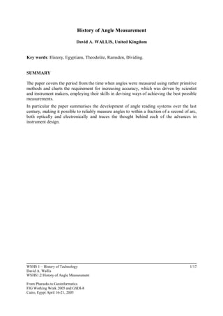
7. CODED CIRCLES
Today the leading companies in the forefront of surveying instrument design and manufacture
are focussing on evermore-sophisticated electronic recording instruments, which read the
angles using binary coded circles. Otto Fennel of Kassel produced the first, rather bulky
electronic Theodolite in Germany. These recorded the encoded readings on film, which when
developed had to be passed through a reader, similar to the early Kine Theodolites produced
by Askania Werk and used for aircraft and missile tracking. Later but equally cumbersome
instruments were produced like the Zeiss REGALTA Electronic Tacheometer, which
recorded distance as well as the angle readings via a punched paper tape.
Binary Coded Circle System
16. WSHS 1 – History of Technology
David A. Wallis
WSHS1.2 History of Angle Measurement
From Pharaohs to Geoinformatics
FIG Working Week 2005 and GSDI-8
Cairo, Egypt April 16-21, 2005
16/17
The Wild T2000 the Kern E1 & E2 and the Zeiss Elta were among the first electronic reading
Theodolite to become popular due to the fact that they were not much large or heavier than a
standard analogue instrument, although they did require rather heavy power supply batteries.
As electronics have become smaller thereby requiring much less power consumption, it has
been possible to integrate the power supply within the body of the instrument. Also the new
generation of electronic Theodolite now incorporates as standard a high degree of computing
power, enabling the user to make on the spot calculations and to store site design information
that speeds the setting out process.
Trimble 3603 Total Station
The emerging developments included automatic target tracking and point "cloud" data capture
speeding up the surveying operation and processing of the data.
REFERENCES
John F. Brock, Pyramids to Pythagoras
James E. Morrison. The Astrolabe
J.J.O'Connor and E.F. Robertson, Pythagoras's theorem in Babylonian Mathematics Science
Museum, London.
James R. Smith ARICS, FRGS. From the Plane to Spheroid 1986
E. Wilfred Taylor, Theodolite Design and Construction 1955.
A.H. Ward FRICS and O. Trutmann, The Theodolite and its Application.1967
17. WSHS 1 – History of Technology
David A. Wallis
WSHS1.2 History of Angle Measurement
From Pharaohs to Geoinformatics
FIG Working Week 2005 and GSDI-8
Cairo, Egypt April 16-21, 2005
17/17
BIOGRAPHICAL NOTE
David A. Wallis Hon.RICS. FBCS. FRSPSoc. FCIM.
He has now retired from the commercial world of surveying instrumentation, having been the
founder of Survey & General Instrument Co. Ltd the general agent for the Kern Company of
Aarau for the United Kingdom.
He has held many offices in learned societies in the fields of surveying and cartography,
including President of the British Photogrammetric Society.
He is a Past Master of the Worshipful Company of Scientific Instrument Makers of the City
of London also a Liveryman of the Spectacle Makers Company.
CONTACT
David A. Wallis
161 Cooden Drive
Bexhill-on-Sea
East Sussex
TN39 3AQ
United Kingdom
Tel. (44) 0 1424 842591
e-mail: davidawallis@alo.com