VIP Call Girls Service Hitech City Hyderabad Call +91-8250192130
Combinational logic
1. ECE 241
Logic Circuit Lab
Lab #4; Page 1/11
Spring 2007
Implementing Combinational Circuits
While Multiplexers are primarily thought of as “data selectors” because they select one of several
inputs to be logically connected to the output, they can also be used to implement Boolean functions.
Similarly, while n-bit Decoders are primarily thought of as n-bit binary to 1 of 2n code converters or as
Demultiplexers, they can also be used to implement Boolean functions of n variables.
1 Multiplexers Used in Boolean Functions
Consider the following truth table that describes a function of 4 Boolean variables.
A B C D F
0 0 0 0 0
0 0 0 1 0
0 0 1 0 1
0 0 1 1 1
0 1 0 0 0
0 1 0 1 1
0 1 1 0 0
0 1 1 1 1
1 0 0 0 0
1 0 0 1 0
1 0 1 0 1
1 0 1 1 1
1 1 0 0 0
1 1 0 1 0
1 1 1 0 0
1 1 1 1 1
MUX 16:1
0
1
2
3
0
1
2
3
4
5
6
7
8
9
10
11
12
13
14
15
G
0
15
F
Vcc D
C
B
A
}
Figure 1: A 16 to 1 Multiplexer Implementation
A 16 to 1 Multiplexer with A, B, C, and D applied to its S3, S2, S1, and S0 inputs respectively would
select one of its 16 inputs for each of the 16 possible combinations of A, B, C, and D. We can implement
the function described by the truth table by connecting a voltage source for logic level 1 or ground for
a logic level 0 to each of the Multiplexer inputs corresponding to the required value of the function
associated with the combination of A, B, C, and D that selected the input. Therefore, the inputs to the
Multiplexer will be the same as the F entries in the truth table provided A, B, C, and D are connected to
the Multiplexer select inputs in the right order.
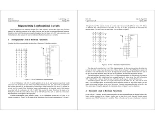
Consider what happens when, instead of using a 16 to 1 Multiplexer, we use an 8 to 1 Mux. If we
choose to connect A, B, and C to the inputs of the Multiplexer, then for each combination of A, B and C,
ECE 241
Logic Circuit Lab
Lab #4; Page 2/11
Spring 2007
although only one Mux input is selected, we need to realize two potentially different values of F. If they
are different, they will be functions of D (either D or D). To see this, we partition the truth table into
sections where A, B and C have the same value. This is shown in Figure 2.
A B C D F
0 0 0 0 0 0
0 0 0 1 0
0 0 1 0 1 1
0 0 1 1 1
0 1 0 0 0 D
0 1 0 1 1
0 1 1 0 0 D
0 1 1 1 1
1 0 0 0 0 0
1 0 0 1 0
1 0 1 0 1 1
1 0 1 1 1
1 1 0 0 0 0
1 1 0 1 0
1 1 1 0 0 D
1 1 1 1 1
Vcc
D
A
B
C
F
MUX 8:1
0
1
2
0
1
2
3
4
5
6
7
G0
7}
Figure 2: An 8 to 1 Multiplexer Implementation
This idea can be extended to a 4 to 1 Mux implementation. In this case we partition the table into
sections for which A and B have the same value. This is shown in Figure 3. Now Multiplexer inputs will
be either 1, 0 or some function of C and D. K-maps may be used to simplify the functions of C and D
for each of the table partitions, but in the case of two variables, the functions are usually obvious.
The final possibility, shown in Figure 4, is a 2 to 1 Mux implementation. In this case only A is used as
a select input and the table is partitioned into two parts based on A. Inputs to the Mux will be functions
of B, C and D. Here it is more likely that you will need to use K-maps to simplify the functions.
It should be apparent that there is no explicit importance to the order of A, B, C and D in the truth
table. If we rearranged them, we would have chosen different variables as Mux select inputs, and we
might end up using less logic in the rest of the circuit. Consider rearranging the table so that B is the
Mux select input. Using this approach, the realization shown in Figure 5 uses less hardware.
2 Decoders Used in Boolean Functions
For an n-bit to 2n Decoder, the only output asserted is the one corresponding to the decimal value of the
binary number presented to the n inputs. Another way to state this is to say that each Decoder output
represents one of the 2n minterms of n variables. Thus, a Decoder can be used to implement a function
2. ECE 241
Logic Circuit Lab
Lab #4; Page 3/11
Spring 2007
A B C D F
0 0 0 0 0
0 0 0 1 0 C
0 0 1 0 1
0 0 1 1 1
0 1 0 0 0
0 1 0 1 1 D
0 1 1 0 0
0 1 1 1 1
1 0 0 0 0
1 0 0 1 0 C
1 0 1 0 1
1 0 1 1 1
1 1 0 0 0
1 1 0 1 0 CD
1 1 1 0 0
1 1 1 1 1
0
1
0
1
2
3
G
0
3
MUX 4:1
F
A
B
C
D
C
C
D
}
Figure 3: A 4 to 1 Multiplexer Implementation
of n variables simply by connecting the outputs of the Decoder that correspond to the minterms of a
function to a multi-input OR gate. Consider the Decoder circuit shown in Figure 6 which implements
two separate functions of three variables. Notice that we have used a 74138 3-to-8 Decoder. As in most
Decoders, the outputs are asserted low. This allows us to use NAND gates to implement the minterm
sums.
We can see that, unlike Multiplexers, Decoders can be used to implement more than one Boolean
function at a time. On the other hand, a Multiplexer implementation may not require any external cir-
cuitry, while a Decoder circuit always needs external gates.
3 Seven-Segment Displays
A Seven-Segment display consists of seven LEDs arranged in a “figure 8,” as shown in Figure 7. Lighting
combinations of the LEDs allows one to display various symbols. To display the symbol 0, we light
segments A, B, C, D, E and F. Lighting segments B and C produces the symbol 1. Because it is a
common anode display, to select a Seven-Segment display a high voltage is applied to the corresponding
anode (A1-A4 on the Digilab Board). Individual LED segments are lit by taking the inputs (the cathodes
CA-CG, DP) associated with the segment low.
Important Note - The seven segment LED’s are active low, meaning you will have to drive the seg-
ment low on the CA - CG, DP pins low in order to light up the LED segments. Example - if CA = 0, then
segment A will light up.
ECE 241
Logic Circuit Lab
Lab #4; Page 4/11
Spring 2007
A B C D F
0 0 0 0 0
0 0 0 1 0
0 0 1 0 1 BC +BD
0 0 1 1 1
0 1 0 0 0
0 1 0 1 1
0 1 1 0 0
0 1 1 1 1
1 0 0 0 0
1 0 0 1 0
1 0 1 0 1 BC +CD
1 0 1 1 1
1 1 0 0 0
1 1 0 1 0
1 1 1 0 0
1 1 1 1 1
F
MUX 2:1
A 0}G
0
1B
D
B
C
C
D
0
1
Figure 4: A 2 to 1 Multiplexer Implementation
Also, in order to select the particular 7 segment group, the common Anodes A1 - A4 must be driven
by Vcc, meaning you will have to connect the A1 - A4 pins to the FPGA and pull them up internally
through an IO Buffer in your schematic entry.
4 Preliminary Exercise (5)
Design a binary to 7-segment code converter for use in displaying a hexadecimal representation of a 4-bit
binary number. (Use lowercase for ‘b’ and ‘d’.) You may use multiplexers and decoders in your design,
as you feel appropriate, as well as primitive gates (e.g., nand gates). Turn in a copy of your complete
design, with necessary documentation, at the start of your lab session. (Written neatly by hand is fine.)
5 Experiment (10)
1. Implement the code converter you designed. Feel free to use components from the Xilinx library.
2. Perform a pre- or post-synthesis simulation of your design.
3. Assign pins to connect your design to switches and displays as needed, by creating a UCF file.
Download your design into the FPGA and demonstrate the functionality to the instructor or TA.
Obtain a signature for your report cover page or the design summary page.
3. ECE 241
Logic Circuit Lab
Lab #4; Page 5/11
Spring 2007
B C D A F
0 0 0 0 0
0 0 0 1 0
0 0 1 0 0 C
0 0 1 1 0
0 1 0 0 1
0 1 0 1 1
0 1 1 0 1
0 1 1 1 1
1 0 0 0 0
1 0 0 1 0
1 0 1 0 1 D(A+C)
1 0 1 1 0
1 1 0 0 0
1 1 0 1 0
1 1 1 0 1
1 1 1 1 1
F
MUX 2:1
0}G
0
1
0
1
B
C
C
A
D
Figure 5: Another 2 to 1 Multiplexer Implementation
6 Report (5)
Turn in a brief, professional report summarizing your experience. Include your design schematics, any
simulations that you performed, and the design summary page.
0
1
2
3
4
5
6
7
1
2
4A
B
C
BIN/OCT
F2
F1
F1(ABC) = ∑m(1,5,7), F2(ABC) = ∑m(0,3,4)
Figure 6: A Decoder Circuit
ECE 241
Logic Circuit Lab
Lab #4; Page 6/11
Spring 2007
DP
A
E
F
DP
B
G
D
C CA
A1
CB CC CD CE CF CG
Figure 7: Seven Segment Display