Manual Segmentation and semantic-based hierarchical tagginf od 3d models

Today 3D objects have become widely available in different application domains, thus it is becoming fundamental to use, integrate and develop techniques for extracting and maintaining their implicit knowledge. These techniques should be encapsulated in intelligent systems able to semantically annotate the 3D models, thus improving their usability and indexing, especially in innovative web cooperative environments. In our work, we are moving in this direction, by defining and developing data structures, methods and interfaces for structuring and semantically annotating 3D complex models (and scenes), even changing over time, according to ontology-driven metadata. In this paper, we focus on tools and methods for manually segmenting manifold 3D models and on the underline structural representation that we build and manipulate. We present also an interface from which the user can inspect and browse the segmentation, describing also the first prototype of an annotation tool which allows a hierarchical semantic-driven tagging of the segmented model.
![OUTLINE ,[object Object],[object Object],[object Object],[object Object],[object Object],[object Object],[object Object],[object Object],November, 2009 EGIT2010 - Laura Papaleo](data:image/gif;base64,R0lGODlhAQABAIAAAAAAAP///yH5BAEAAAAALAAAAAABAAEAAAIBRAA7)
Recommandé
Recommandé
Contenu connexe
En vedette
En vedette (20)
Similaire à Manual Segmentation and semantic-based hierarchical tagginf od 3d models
Similaire à Manual Segmentation and semantic-based hierarchical tagginf od 3d models (20)
Manual Segmentation and semantic-based hierarchical tagginf od 3d models
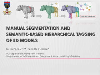
- 1. MANUAL SEGMENTATION AND SEMANTIC-BASED HIERARCHICAL TAGGING OF 3D MODELS Laura Papaleo*^, Leila De Floriani^ * ICT Department, Province of Genova ^Department of Information and Computer Science University of Genova
Notes de l'éditeur
- In this presentation I’m going to present the results in the development of a semantic web system for 3D shape understanding and annotation. The system can be located in a more wide framework of research that research group I belong to has established with the RPI Department of Cognitive Science leaded by Prof J. Hendler. this slide is just to remind that the activity we are working on in this paper is related to digital representations of 3D object and 3D objects are becoming widely available on the net and used in many disciplines. There is so a general need of organizing these representations in an intelligent way. One of the first project in this sense was a NSF project in 2002 which concentrated mainly on medical 3D objects and the way in which this objects can be analyzed and organized… to be searched well. In any case the key in this framework is to extract knowledge from digital representations and maintain that in order also to efficiently search and retrieve and eventually reason on them.
- Semantic Web proposes annotating document content using semantic information. The result is multimedia content with machine interpretable mark-up that provide the source material with which agents and SemanticWeb services operate, thus creating annotations with well-defined semantics.
- Qui diciamo che tutto il ragionamento relativo all’oggetto (o alla scena) viene fatto basandosi su una rappresentazione a grafo Il grafo si chiama segmentation graph ed è un two-level segmentation graph. Il primo livello (attivo nel caso di modelli non-manifold) etc Il secondo livello si chiama manifodl segmentation graph Le informazioni semantiche verranno associate ai nodi del grafo (o eventualmente, se necessario anche agli archi) e quindi alle porzioni di oggetto…
- In our case, since X3D allows to define shapes using vertices and not edges, the use of an implementation of the original approach would have been computationally expensive. Every time the user would draw the stroke, the system should compute the intersection between a circle of radius r and all the edges present in the scene and projected on the viewplane.We decided to apply the algorithm on the vertices of the model. This change does not modify the general methodology, but it allows us to reduce the number of operations to be performed.With our choice, in fact, we do not have to compute intersections (solving linear systems) but only euclidean distances. Additionally, we have been able to extend the procedure to surface meshes which are not represented only by triangles, using in this way all the faces types defined by the X3D standard. Furthermore, we extended the method to special cases: we can treat the case in which, given a stroke (as a set of circles) there is no vertex inside it connecting the initial and final vertex of the stroke: each time we cannot find a connection inside the stroke, we search for the nearest point in the surface model and we let the path passing from it. This procedure solves also the case in which, given the stroke, the system cannot find an initial and/or final vertex. For automatic computation of the cut in the not visible part of the model, we improved the original method restricting the search of the connections to a subset of vertices. For doing this we compute the visibility of each vertex before performing the cut.
- In our case, since X3D allows to define shapes using vertices and not edges, the use of an implementation of the original approach would have been computationally expensive. Every time the user would draw the stroke, the system should compute the intersection between a circle of radius r and all the edges present in the scene and projected on the viewplane.We decided to apply the algorithm on the vertices of the model. This change does not modify the general methodology, but it allows us to reduce the number of operations to be performed.With our choice, in fact, we do not have to compute intersections (solving linear systems) but only euclidean distances. Additionally, we have been able to extend the procedure to surface meshes which are not represented only by triangles, using in this way all the faces types defined by the X3D standard. Furthermore, we extended the method to special cases: we can treat the case in which, given a stroke (as a set of circles) there is no vertex inside it connecting the initial and final vertex of the stroke: each time we cannot find a connection inside the stroke, we search for the nearest point in the surface model and we let the path passing from it. This procedure solves also the case in which, given the stroke, the system cannot find an initial and/or final vertex. For automatic computation of the cut in the not visible part of the model, we improved the original method restricting the search of the connections to a subset of vertices. For doing this we compute the visibility of each vertex before performing the cut.
- In our case, since X3D allows to define shapes using vertices and not edges, the use of an implementation of the original approach would have been computationally expensive. Every time the user would draw the stroke, the system should compute the intersection between a circle of radius r and all the edges present in the scene and projected on the viewplane.We decided to apply the algorithm on the vertices of the model. This change does not modify the general methodology, but it allows us to reduce the number of operations to be performed.With our choice, in fact, we do not have to compute intersections (solving linear systems) but only euclidean distances. Additionally, we have been able to extend the procedure to surface meshes which are not represented only by triangles, using in this way all the faces types defined by the X3D standard. Furthermore, we extended the method to special cases: we can treat the case in which, given a stroke (as a set of circles) there is no vertex inside it connecting the initial and final vertex of the stroke: each time we cannot find a connection inside the stroke, we search for the nearest point in the surface model and we let the path passing from it. This procedure solves also the case in which, given the stroke, the system cannot find an initial and/or final vertex. For automatic computation of the cut in the not visible part of the model, we improved the original method restricting the search of the connections to a subset of vertices. For doing this we compute the visibility of each vertex before performing the cut.
- Some notes: using our tags - organized hierarchically - we are able to re-merge the segmented regions simply by checking the names of the regions and by merging their faces and vertices. looking at the name of a given region C we can access immediately to its history.
- one tab collects the geometrical information, automatically extracted (geometry); another tab (adjacency) describes the adjacency information, again automatically extracted. The last working tab (semantic) is, instead, devoted to the userdefined semantic annotation.
- La visualizzazione del grafo per adesso è per modelli manifold