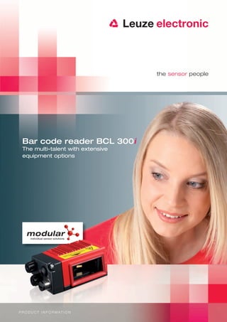
1. Bar code reader BCL 300i
The multi-talent with extensive
equipment options
modular
individual sensor solutions
P R O D U C T I N F O R M AT I O N
2. You decide
what your bar code reader can do.
The bar code readers of the BCL 300i series
set new standards in equipment options.
What makes our new BCL 300i series special is its modularity. For the first
time, you can select from a large number of equipment options to individually
configure a device optimally for your application. You thereby obtain a bar code
reader perfectly tailored to your needs with regard to function, connection,
mounting, and operation and one that stands for reliability and system
availability.
Top performance and practical innovation in all areas
The BCL 300i convinces not only with its proven performance characteristics
such as the high-performance code reconstruction technology, the integrated
fieldbus connectivity and the—in this performance class—unrivalled optical data
at long operating range and wide opening angle.
With the unique hood with integrated connectors, the device can also be quickly
connected to your fieldbus environment without complicated plug mounting.
In addition, the compact scanner can be used as an Ethernet switch in the
network and can be configured either via the browser-based webConfig tool
conveniently and directly via Ethernet or directly in the PROFIBUS / PROFINET
environment.
3. Compromises are a thing of the past –
today the word is modular.
modular
ind ivi du al se ns
or so lut io ns
With the new BCL 300i, select between freely combinable equipment variants.
We call this flexible type of product configuration modular.
Optics / read fields
Display elements High Density (N)
Medium Density (M)
Graphical display
Low Density (F)
LED display
Ultra Low Density (L)
Scanner
Oscillating mirror
Deflection mirror
Front scanner
Line scanner
Raster scanner
Options
Heating
Mounting systems
Interfaces
Connection technology PROFIBUS
PROFINET
Modular connector hood
Ethernet TCP/IP
Modular terminal hood
multiNet
Modular connection box
RS 232 / 422 / 485
Connection cable
4. Convincing performance characteristics:
The advantages of the BCL 300i at a glance.
modular
individual sensor solutions
Modularity Full CRT (code reconstruc- High-quality optics
tion technology)
First bar code reader with freely The most powerful code reconstruction The used optics facilitate a large depth
combinable equipment for optimum technology on the market; also reliably of field and wide opening angle for
adaptation to your application. detects heavily damaged or soiled reliable detection, even with wide
codes. conveyor lines.
Integrated fieldbus webConfig Ethernet switch
connectivity = i
A range of available fieldbus interfaces Operating-system independent, The device can function as an Ethernet
enables direct integration and configura- browser-based configuration tool. switch to create a linearly structured
tion of the system without additional network.
software.
Flexible electrical Small construction
connection
For the BCL 300i, you can select from Compact housing design for problem-
four different connection options. free placement directly at the conveyor
line.
5. Configuration made simple.
The fast track to custom configuration
of your bar code reader.
The Leuze electronic BCL 300i webConfig.
With the integrated webConfig tool,
an operating-system independent,
web-technology based, multi-language
user interface is available for configuri-
ng the device. The individual parame-
ters are presented in an easy-to-un-
derstand, graphic form.
The BCL 300i in the PROFIBUS /PROFINET world.
With the integrated PROFIBUS or the
integrated PROFINET, it is possible
to configure the BCL 300i via the
module structure contained in the
GSD / GSDML file directly via the
HW Config. In doing so, the parame-
ters that are set are stored in the
control and, should a device need to
be replaced, automatically transferred
to the new device.
6. Diverse application possibilities
Pallet ID Container identification
Container identification Container identification
with variable heights from the side
Container identification
Tray identification
with autoReflAct
7. Reading field curves High Density (N) Reading field curves Medium Density (M)
BCL 3xxi S/R1 N 102 – line scanner w/o deflection mirror BCL 3xxi S/R1 M 102 – line scanner w/o deflection mirror
100 150
75 m = 0.127 m = 0.2
Reading field width [mm]
Reading field width [mm]
100
50
m = 0.15 m = 0.3
50
25
m = 0.127
m = 0.15
0 m = 0.2
m = 0.2
m = 0.3
m = 0.5
m = 0.2 0 m = 0.5
-25
-50
-50
-100
-75
-100 -150
0 25 50 75 100 125 150 175 200 225 250 275 300 0 50 100 150 200 250 300 350 400 450
Read distance [mm] Read distance [mm]
BCL 3xxi S/R1 N 100 – line scanner w/ deflection mirror BCL 3xxi S/R1 M 100 – line scanner w/ deflection mirror
100 150
75 m = 0.127 m = 0.2
Reading field width [mm]
Reading field width [mm]
100
50
m = 0.15 m = 0.3
50
25
m = 0.127
m = 0.15
m = 0.2
0
m = 0.2
m = 0.3
m = 0.5
m = 0.2 0 m = 0.5
-25
-50
-50
-100
-75
-100 -150
0 25 50 75 100 125 150 175 200 225 250 275 300 0 50 100 150 200 250 300 350 400 450
Read distance [mm] Read distance [mm]
BCL 3xxi ON 100 – for oscillating-mirror scanner BCL 3xxi OM 100 – for oscillating-mirror scanner
100 150
75 m = 0.127 m = 0.2
Reading field width [mm]
Reading field width [mm]
100
50
m = 0.15 m = 0.3
50
25
m = 0.127
m = 0.15
m = 0.2
0
m = 0.5
m = 0.2
m = 0.3
m = 0.2 0 m = 0.5
-25
-50
-50
-100
-75
-100 -150
0 25 50 75 100 125 150 175 200 225 250 275 300 0 50 100 150 200 250 300 350 400 450
Read distance [mm] Read distance [mm]
BCL 3xxi ON 100 – lat. oscillating-mirror scanner BCL 3xxi OM 100 – lat. oscillating-mirror scanner
100 150
80 125
m = 0.127 m = 0.2
Reading field width [mm]
Reading field width [mm]
100
60
75
40 m = 0.15 m = 0.3
50
20
m = 0.127
25
m = 0.15
m = 0.2
m = 0.2
m = 0.3
m = 0.5
0 m = 0.2 0 m = 0.5
-22 25
50
-40
75
-60
100
-80 125
-100 150
0 25 50 75 100 125 150 175 200 225 250 275 300 0 50 100 150 200 250 300 350 400 450
Read distance [mm] Read distance [mm]
8. Reading field curves Low Density (F) Reading field curves Ultra Low Density (L)
BCL 3xxi S/R1 F 102 – line scanner w/o deflection mirror BCL 3xxi S/R1 L 102 – line scanner w/o deflection mirror
200 300
250
150 m = 0.3 m = 0.35
Reading field width [mm]
Reading field width [mm]
200
100 150
m = 0.35 m = 0.5
100
50
m = 0.35 50
m = 0.35
m = 0.5
m = 0.5
m = 0.8
m = 0.3
0 m = 0.5 0 m = 0.8
-50
-50
-100
-100 -150
-200
-150
-250
-200 -300
0 50 100 150 200 250 300 350 400 450 500 550 600 0 50 100 150 200 250 300 350 400 450 500 550 600 650 700 750
Read distance [mm] Read distance [mm]
BCL 3xxi S/R1 F 100 – line scanner w/ deflection mirror BCL 3xxi S/R1 L 100 – line scanner w/ deflection mirror
200 300
250
150 m = 0.3 m = 0.35
Reading field width [mm]
Reading field width [mm]
200
100 150
m = 0.35 m = 0.5
100
50
50
m = 0.35
m = 0.35
m = 0.5
m = 0.5
m = 0.8
m = 0.3
0 m = 0.5 0 m = 0.8
-50
-50
-100
-100 -150
-200
-150
-250
-200 -300
0 50 100 150 200 250 300 350 400 450 500 550 600 0 50 100 150 200 250 300 350 400 450 500 550 600 650 700 750
Read distance [mm] Read distance [mm]
BCL 3xxi OF 100 – for oscillating-mirror scanner BCL 3xxi OL 100 – for oscillating-mirror scanner
200 300
250
150 m = 0.3 m = 0.35
Reading field width [mm]
Reading field width [mm]
200
100 150
m = 0.35 m = 0.5
100
50
50
m = 0.35
m = 0.35
m = 0.5
m = 0.3
m = 0.5
m = 0.8
0 m = 0.5 0 m = 0.8
-50
-50
-100
-100 -150
-200
-150
-250
-200 -300
0 50 100 150 200 250 300 350 400 450 500 550 600 0 50 100 150 200 250 300 350 400 450 500 550 600 650 700 750
Read distance [mm] Read distance [mm]
BCL 3xxi OF 100 – lat. oscillating-mirror scanner BCL 3xxi OL 100 – lat. oscillating-mirror scanner
200 300
250
150 m = 0.3 m = 0.35
Reading field width [mm]
Reading field width [mm]
200
100 150
m = 0.35 m = 0.5
100
50
50
m = 0.35
m = 0.35
m = 0.5
m = 0.3
m = 0.5
m = 0.8
0 m = 0.5 0 m = 0.8
-50
-50
-100
-100 -150
-200
-150
-250
-200 -300
0 50 100 150 200 250 300 350 400 450 500 550 600 0 50 100 150 200 250 300 350 400 450 500 550 600 650 700 750
Read distance [mm] Read distance [mm]
9. BCL 300i BCL 301i BCL 304i BCL 308i BCL 348i
Line scanner Specifications of the line scanners without heating
Type
Line scanner without heating* Standalone multiNet Plus Slave PROFIBUS DP Ethernet PROFINET
Optical data
Light source Laser diode = 655 nm
Beam exit At the front
Scanning rate 1,000 scans/s
Useful opening angle Max. 60°
Optics models / resolution High density (N): 0.127 – 0.2 mm; medium density (M): 0.2 – 0.5 mm; low density (F): 0.3 – 0.8 mm; ultra low density (L): 0.35 – 0.8 mm
Read distance See reading field curves
Laser safety class 2 acc. to EN 60825-1, CDRH (U.S. 21 CFR 1040.10)
Bar code data
Code types 2/5 Interleaved, Code 39, Code 128, EAN / UPC, Codabar, Code 93, RSS 14
Number of bar codes per scan 6
Electrical data
External connection box (MA 100) External connection box (MA 100)
M12 via MS 304 M12 via MS 308 M12 via MS 348
Interface type M12 via MS 300 M12 via MS 301
Terminals via MK 304 Terminals via MK 308 Terminals via MK 348
Terminals via MK 300 Terminals via MK 301
Leuze standard,
Leuze standard, PROFINET / RT,
Protocols ACK/NAK, 3964 (R), RK 512, PROFIBUS DP Ethernet, TCP / IP / UDP
Leuze multiNet plus TCP / IP, UDP
Xon/Xoff
Baud rate 4,800 ... 115,400 Baud 4,800 ... 115,400 Baud 9.6 Kbaud –12 MBaud 10 / 100 MBaud 10 / 100 MBaud
Data bits: 7,8 / Stop bits: 1,2 Data bits: 7,8 / Stop bits: 1,2
Data formats Slave DPV1 – –
Parity: None, Even, Odd Parity: None, Even, Odd
Service interface USB 2.0 Mini-B type socket
Operating voltage 18 ... 30 V DC (SK III, class 2)
Power consumption Approx. 4 W
Operating and display elements
Display (optional) Monochromatic graphical display, 128 × 32 pixel, background lighting (optional)
Keyboard (optional) 2 buttons
LEDs 2 LEDs for power (PWR) and bus state (BUS), two-colored (red/green)
Mechanical data
Protection class only with MS / MK / KB
IP 65
connection hoods
Weight 270 g
Dimensions (W × H × D) 44 × 95 × 68 mm
Housing Diecast aluminum
Environmental data
Operating temperature range 0 °C – +40 °C
Storage temperature range -20 °C – +70 °C
Air humidity Air humidity max. 90 % rel. humidity, non-condensing
Vibration IEC 60068-2-6, test FC
Shock IEC 60068-2-27, test Ea
Continuous shock IEC 60068-2-29, test Eb
Electromag. compatibility EN 55022, EN 61326-1; IEC 61000-6-2 (includes IEC 61000-4-2, -3, -4, -5 and -6)
Line scanner with oscillating mirror Technical data same as for line scanner without heating, however with the following differences:
Type
Line scanner with oscillating mirror w/o heating* Standalone multiNet Plus Slave PROFIBUS DP Ethernet PROFINET / RT, TCP / IP
Optical data
Beam exit Lateral zero position at an angle of 90°
Oscillation frequency 0-10 Hz (adjustable, max. frequency is dependent on set swivel angle)
Max. swivel angle +/- 20° (adjustable)
Electrical data
Power consumption Approx. 10 W
Mechanical data
Weight 580 g
Dimensions (W × H × D) 58 × 125 × 110 mm
Line scanner with deflection mirror Technical data same as for line scanner without heating, however with the following differences:
Type
Line scanner with deflection mirror w/o heating* Standalone multiNet Plus Slave PROFIBUS DP Ethernet PROFINET / RT, TCP / IP
Optical data
Beam exit Optical data - beam exit with lateral zero position at an angle of 105°
Electrical data
Power consumption Approx. 4 W
Mechanical data
Weight 350 g
Dimensions (W× H × D) 44 × 103 × 96 mm
10. Optoelectronic Sensors
Cubic series
Cylindrical Sensors, Mini Sensors, Fiber Optic Amplifiers
Measuring Sensors
Special Sensors
Light Curtains
Forked Sensors
Double Sheet Monitoring, Splice Detection
Inductive Switches
Accessories
Identification Systems
Data Transmission Systems
Distance Measurement
Bar Code Readers
RF-IDent-Systems
Modular Interfacing Units
Industrial Image Processing Systems
Optical Data Transmission Systems
Optical Distance Measurement/Positioning
Mobile Code Readers
Safety Sensors
Safety Systems
Safety Services
Safety Laser Scanner
Safety Light Curtains
Transceivers and Multiple Light Beam Safety Devices
Single Light Beam Safety Devices
AS-i-Safety Product Range
Safety Sensor Technology for PROFIBUS DP
Safety Switches, Safety Locking Devices, Safety Command Devices
Safety Relays
Sensor Accessories and Signal Devices
Safety Engineering Software
Machine Safety Services
Leuze electronic GmbH + Co. KG
en 01-2011/09 50116993
In der Braike 1
D-73277 Owen/Germany
Phone +49 (0) 7021 / 573-0
Fax +49 (0) 7021 / 573-199
info@leuze.de
www.leuze.com