1. ABOVE COUNTER INSTALLATION (100662)
AB OV E C OUNTER INS TALLATION AT TAC H IN G T H E D IV ER T ER
The eSpring Water Purifier sits on the countertop with the Diverter and tubing 1. Unscrew to remove the aerator Fig. 2
attached directly to your faucet. Both the diverter and tubing should be replaced (wire screen) and washer from the
every two years. end of your faucet (Fig. 2).
NOTE: Attach the Diverter to a faucet that will supply COLD, POTABLE WATER to the
Water Purifier. DO NOT RUN HOT WATER THROUGH THE WATER PURIFIER.
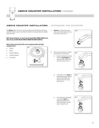
Check to make sure you have all the correct components before you begin
installation (Fig 1).
Fig. 1
a. Diverter
b. Tubing
a
2. There are three options for attach-
c. 3 faucet adapters Fig. 3
ing the Diverter to the faucet.
b
d. 2 tubing supports
a) Position the Diverter onto the
e. 2 tie straps faucet and hand tighten the
textured collar counterclock-
c d
wise until secure (Fig. 3).
e
b) If that does not fit, attach the Fig. 4
appropriate textured adapter
with internal threads and
washer to the end of your
faucet (Fig. 4).
c) If the threads on your faucet Fig. 5
are internal, attach the
appropriate adapter with
external threads to the end
of your faucet (Fig. 5).
1
2. AT TA C H ING T H E T U B I N G AT TAC H IN G T U B IN G T O WATER
TO THE D IV E R T E R P U RIF IER AN D C H EC KIN G FOR
L EAK S
Fig. 6
1. Unscrew to remove the textured
nuts (Fig. 6).
**MAKE SURE THE UNIT IS NOT PLUGGED INTO AN ELECTRICAL OUTLET.
1. Position the eSpringTM Fig. 11
Water Purifier in a
desired location where
the tubing from the fau-
cet reaches the Water
Purifier and the Power
Adapter reaches an
Fig. 7 outlet with continuous
2. With the threads facing out, push power (Fig. 11).
the large nut on the large tube and
the small nut on the small tube
(Fig. 7).
2. Remove the Top Shroud (Fig. 12). Fig. 12
3. Firmly push the large tube onto the Fig. 8
large barb and the small tube onto
the small barb (Fig. 8).
Fig. 13
3. Remove the Electronic Module
(Fig. 13).
4. Screw the nuts onto the barbs and Fig. 9
hand tighten (Fig. 9).
4. If the tubing is too long, use a
Fig. 14
sharp knife to cut the tubes at the
same length where they are NOT
BONDED TOGETHER. Make sure to
make a straight cut to form a flat
end on the tubes (Fig. 14).
5. Use the tie straps to secure the Fig. 10
tubing to the faucet (Fig. 10).
2
3. AT TA C H ING T U B I N G T O WAT ER P U RIF IER AN D C H EC KIN G F O R L EAKS
5. Lay the large tube on top of Fig. 15 8. The Diverter controls the flow of
⁄ "(
34 ) Fig. 19
the diagram and the small water according to the position of
tube on the bottom of the the pin.
diagram and use a pen to
a) Pin pulled out - Treated water
mark a line across each tube
(Fig. 19).
at the arrows (Fig. 15).
b) Pin pushed in - Untreated
water (Fig. 20).
9. Turn on cold water faucet and pull
out the Diverter pin.
58⁄ "( ) NOTE: It will take a short time for water
to saturate the Cartridge and flow from
the Diverter. Flush for 5 minutes to
6. Push tubing supports into their Fig. 16 remove air pockets and carbon dust. It
respective tubes (Fig. 16). may take 5-15 minutes to clear.
Fig. 20
7. Insert each tube into the proper Fig. 17
locations on the Bracket until you
meet the marks or the marks
disappear (Fig. 17 & 18).
NOTE: You will feel resistance before the
tube is fully installed.
10. Check for any signs
Fig. 21
of leakage at the
Diverter and at all
tubing connections (Fig.
21). If there is leaking
or bubbling, refer to
Troubleshooting in the
manual (p. 12).
Fig. 18
11. Push in the pin and turn
off the water after each
use.
3
4. COM P LETING T H E I N S TA L L AT IO N
1. Insert Power Adapter into Fig. 22 4. Store the removal tool for future Fig. 25
Electronic Module (Fig. 22). use (Fig. 25).
Fig. 23
2. Replace the Electronic Module 5. Place the Top Shroud onto Base Fig. 26
(Fig. 23). Housing (Fig. 26).
Fig. 24
3. Push cord strain relief into notch
on Base Housing (Fig. 24).
NOTE: Make sure the tubes are in the
notches on the back of the Base Housing. 6. Plug the Power Adapter into wall Fig. 27
outlet (Fig. 27).
7. Wait for monitor to signal with a
beep. This may take 30 seconds.
8. Turn on cold water faucet and pull
out the Diverter pin to run water
through the Water Purifier. Make
sure the display has a blue cup
(p. 11). If not, refer to Trouble-
shooting in the manual, Auditory
Warnings (p.13).
4
5. I N S TALLATIO N S UR LE COMPTOIR (100662)
I N S TA LLAT IO N S UR LE B RAN C H EM EN T D E
C O M PT OI R L A D ÉR IVAT IO N
1. Dévissez et enlevez le brise-jet Schéma 2
Le Purificateur d’Eau eSpring est posé sur le comptoir, la dérivation et le tubage (tamis) et la rondelle se trouvant à
étant directement attachés au robinet. L’autre la dérivation et le tubage devrait l’extrémité du robinet (Schéma 2).
être remplacé tous les deux ans.
REMARQUE: Attacher la dérivation au robinet qui fournit l’EAU FROIDE ET POTABLE
au Purificateur d’Eau. NE PAS FAIRE COULER L’EAU CHAUDE DANS LE PURIFICATEUR
D’EAU.
Avant d’entreprendre l’installation, Schéma 1
vérifiez que vous avez bien toutes les
pièces nécessaires (Schéma 1).
a 2. Vous disposez de trois options Schéma 3
a) Dérivation pour connecter la dérivation au
b) Tubage b robinet.
c) 3 adaptateurs pour robinet a) Positionnez la dérivation sur
le robinet et serrez à la main
d) 2 supports pour tuyau d le collet texturé dans le sens
c
e) 2 attaches contraire des aiguilles d’une
e montre jusqu’à ce qu’il soit
sécurisé (Schéma 3).
b) Si cela ne marche pas, con- Schéma 4
nectez l’adaptateur texturé
approprié aux filetages in-
ternes et le brise-jet au bout
du robinet (Schéma 4).
Schéma 5
c) Si le filetage du robinet
est interne, connectez
l’adaptateur approprié au
filetage externe au bout du
robinet (Schéma 5).
1
6. BRA NCHEM E N T D U T U B A G E C O N N EC T IO N D U T U B AG E A U
À LA D ÉR IVAT I ON P U RIF IC AT EU R D ’ EAU
ET V ÉR IF IC AT IO N AN T I- F U ITE
Schéma 6
1. Dévissez les écrous texturés pour
les enlever (Schéma 6).
**S’ASSURER QUE L’APPAREIL N’EST PAS BRANCHÉ À UNE PRISE ÉLECTRIQUE.
1. Placez le Purificateur Schéma 11
d’Eau eSpringTM à
l’endroit désiré où
le tubage du robinet
puisse arriver jusqu’au
Purificateur d’Eau et où
l’adaptateur de courant
2. Le filetage faisant face à vous, puisse atteindre la
poussez le gros écrou sur le gros Schéma 7
prise électrique à
tuyau et le petit écrou sur le petit puissance continue
tuyau (Schéma 7). (Schéma 11).
Schéma 12
2. Enlevez le boîtier supérieur
(Schéma 12).
3. Poussez fermement le gros tuyau Schéma 8
dans la grosse barbelure et le
petit tuyau dans la petite barbelure
(Schéma 8).
3. Enlevez le module électronique
Schéma 13
(Schéma 13).
4. Vissez les écrous aux barbelures et
serrez à la main (Schéma 9). Schéma 9
4. Si le tubage est trop long, utilisez Schéma 14
un couteau affûté pour couper les
tubes à la même longueur là où ils
NE SONT PAS JOINTS ENSEMBLE.
Veillez à couper bien droit pour
former une extrémité plate au bout
5. Utilisez les attaches pour sécuriser des tubes (Schéma 14).
Schéma 10
le tubage au robinet (Schéma 10).
2
7. CONNECTIO N DU T U B A G E A U P U RIF IC AT EU R D ’ EAU
ET V É R IFIC AT I ON A N T I -F U I T E
5. Posez le gros tube dessus le Schéma 15 8. La dérivation contrôle le débit Schéma 19
diagramme et le petit tube au d’eau en fonction de la position
bas du diagramme, et utilisez de l’ergot.
un stylo pour tracer un trait a) Ergot tiré – Eau traitée
sur chaque tube au niveau des (Schéma 19).
flèches (Schéma 15).
b) Ergot poussé – Eau non
traitée (Schéma 20).
9. Ouvrez le robinet d’eau froide et
tirez l’ergot de la dérivation.
REMARQUE: Il faut un peu de temps pour
que l’eau sature la cartouche et com-
mence à couler de la dérivation. Laissez
6. Poussez les supports de tuyau Schéma 16
couler l’eau pendant 5 minutes afin
dans les tubes appropriés d’éliminer les poches d’air et la pous-
(Schéma 16). sière de carbone. Il faut compter entre
5 et 15 minutes pour les dégager.
Schéma 20
7. Insérez chaque tube aux endroits Schéma 17
appropriés sur le support de
fixation jusqu’à ce que vous ar-
riviez aux traits ou que les traits
disparaissent (Schémas 17 et 18).
REMARQUE: Vous sentirez une résis-
tance avant que le tube soit entièrement 10. Vérifiez qu’il n’y a pas de Schéma 21
installé. fuite au niveau de la dériva-
tion et à tous les raccords
de tubes (Schéma 21). S’il
y a des fuites ou des bulles
d’eau, consultez la section
Dépannage dans le manuel
Schéma 18 (p. 12).
11. Poussez l’ergot et arrêtez
l’eau après chaque utilisation.
3
8. TER M INER L’ I N S TA L L AT I ON
1. Insérez l’adaptateur de courant Schéma 22 4. Rangez l’outil d’extraction pour une Schéma 25
dans le module électronique utilisation ultérieure (Schéma 25).
(Schéma 22).
2. Replacez le module électronique Schéma 23
5. Mettez le boîtier supérieur sur le Schéma 26
(Schéma 23).
socle (Schéma 26).
3. Poussez la bride de cordon dans Schéma 24
l’encoche du socle (Schéma 24).
REMARQUE: Veillez à ce que les tubes 6. Branchez l’adaptateur de courant à Schéma 27
soient dans les encoches au dos du socle. la prise électrique (Schéma 27).
7. Attendez que le dispositif de con-
trôle émette un signal sonore. Ceci
peut prendre 30 secondes.
8. Ouvrez le robinet d’eau froide et
tirez l’ergot de la dérivation pour
faire passer l’eau à travers le
Purificateur d’Eau. Vérifiez qu’il y
a une tasse bleue sur l’affichage
(page 11). Si ce n’est pas le cas,
consultez la section Dépannage
dans le manuel, Avertissements
Sonores (p. 13).
4
9. I N STALACIÓ N S O BRE LA SUPERFICIE
DEL MO S TR AD O R (100662)
I N S TA LA C I Ó N S O BR E LA IN STAL AC IÓ N D EL D ES V IADOR
SU P ER F I C I E D EL MO S TR AD OR
El Purificador de agua eSpring se acomoda en la superficie del mostrador con el 1. Destornille para quitar el aerador Fig. 2
desviador y la tubería montados directamente al grifo. El desviador y la tubería (rejilla metálica) y la arandela del
se debe cambiar cada dos años. extremo del grifo (Fig. 2).
NOTA: Instale el desviador a un grifo con suministro de AGUA FRÍA Y POTABLE al
Purificador de agua. NO DEJE PASAR AGUA CALIENTE POR EL PURIFICADOR
DE AGUA.
Fig. 1
Asegúrese de tener todos los compo-
nentes correctos antes de iniciar la
instalación (Fig. 1). a
a. Desviador b 2. Hay tres opciones para instalar el Fig. 3
b. Tubería Desviador al grifo.
c. 3 adaptadores de grifo a) Acomode el Desviador en el
c d grifo y apriete a mano el co-
d. 2 soportes de la tubería
llarín texturizado en sentido
e. 2 correas de amarre e contrario a las manecillas
del reloj hasta que quede fijo
(Fig. 3).
b) Si no se adapta bien, monte Fig. 4
el adaptador texturizado ad-
ecuado con roscas internas
y la arandela al extremo del
grifo (Fig. 4).
c) Si las roscas del grifo son Fig. 5
internas, monte el adaptador
adecuado con las roscas
externas al extremo del grifo
(Fig. 5).
1
10. MONTA JE DE L A T U B E R Í A M O N TAJ E D E L A T U B ER ÍA AL
AL D E S V IAD O R P U RIF IC AD O R D E
AG U A Y REV IS IÓ N D E F U G A S
Fig. 6
1. Destornille para quitar las tuercas
texturizadas (Fig. 6).
**ASEGÚRESE DE QUE LA UNIDAD NO ESTÉ CONECTADA A UNA SALIDA ELÉCTRICA.
1. Acomode el Purificador Fig. 11
de agua eSpring™ en
un sitio deseado donde
la tubería del grifo
alcance el Purificador
de agua y el Adaptador
de energía alcance una
2. Con las roscas hacia fuera, empuje salida eléctrica con
la tuerca grande sobre el tubo Fig. 7 corriente continua
grande y la tuerca pequeña sobre (Fig. 11).
el tubo pequeño (Fig. 7).
2. Quite el Recubrimiento superior Fig. 12
(Fig. 12).
3. Oprima firmemente el tubo grande Fig. 8
sobre la púa grande y el tubo
pequeño sobre la púa pequeña
(Fig. 8).
3. Quite el Módulo electrónico Fig. 13
(Fig. 13).
4. Atornille las tuercas en las púas y
apriete a mano (Fig. 9). Fig. 9
4. Si la tubería es demasiado larga, Fig. 14
use un cuchillo afilado para cortar
los tubos a la misma longitud de
manera que NO SE ENREDEN.
Asegúrese de hacer un corte recto
para formar un extremo plano en
5. Use las correas de amarre para los tubos (Fig. 14).
Fig. 10
asegurar la tubería al grifo
(Fig. 10).
2
11. Fig. 15 8. El Desviador controla el flujo Fig. 19
5. Coloque el tubo largo en la parte ⁄ pulg. (
34 ) de agua según la posición de
superior del diagrama y el tubo la clavija.
pequeño en la parte inferior del
diagrama y use una pluma para a) Clavija sacada – Agua purifi-
marcar una línea a través de cada (Fig. 19).
cada tubo en las flechas b) Clavija metida – Agua no
(Fig. 15). purificada (Fig. 20).
9. Abra el grifo del agua fría y tire de
la clavija del desviador.
NOTA: Transcurrirá un período corto para
⁄ pulg. (
58 ) que el agua sature el Cartucho y fluya del
Desviador. Deje pasar el agua 5 minutos
para eliminar bolsas de aire y polvo de
Fig. 16 carbono. Puede tardar de 5 a 15 minutos
6. Empuje los soportes de la tubería a
para despejarse.
sus respectivos tubos (Fig. 16).
Fig. 20
Fig. 17
7. Introduzca cada tubo en los
sitios correspondientes del
soporte hasta que coincida con
las marcas o éstas desaparezcan
(Figuras 17 y 18).
Fig. 21
NOTA: Sentirá resistencia antes de que el 10. Revise si hay señales
tubo esté completamente instalado. de fuga al Desviador
y a las conexiones de
la tubería (Fig. 21). Si
hay fugas o burbujas,
consulte la sección de
Reparación de averías
Fig. 18 en el manual (pág. 12).
11. Empuje la clavija y
cierre el agua después
de cada uso.
3
12. FINA LIZA R L A I N S TA L A C I ÓN
1. Introduzca el Adaptador de energía Fig. 22 4. Guarde la herramienta de remoción Fig. 25
al Módulo electrónico (Fig. 22). para uso futuro (Fig. 25).
Fig. 23
2. Coloque nuevamente el Módulo 5. Coloque el Recubrimiento superior Fig. 26
electrónico (Fig. 23). en el Armazón de la base (Fig. 26).
Fig. 24
3. Oprima la liberación del cable en
la muesca del Armazón de la base
(Fig. 24) Fig. 27
6. Enchufe el Adaptador de energía
NOTA: Asegúrese de que los tubos estén
a la salida eléctrica de la pared
en las muescas en la parte posterior del
(Fig. 27).
Armazón de la base.
7. Espere a que el monitor dé una
señal con un sonido. Esto puede
tardar 30 segundos.
8. Abra el grifo de agua fría y estire
la clavija del desviador para que el
agua corra por el Purificador de
agua. Asegúrese de que la pan-
talla tenga un vaso azul (pág. 11).
Si no tiene, consulte la sección de
Reparación de averías en el manual,
Advertencias Audibles (pág. 13).
4