Formate matters-issue-5
•
0 j'aime•524 vues

The document discusses eco-efficiency analysis conducted by BASF to compare the eco-efficiency of formate brines and bromide brines. The analysis found that formate brines were significantly more eco-efficient than bromide brines. Formate brines scored better on costs, lower toxicity potential, and lower emissions. In particular, bromide brines produced large amounts of toxic waste that required special treatment. While formate brines required more salt overall, they offered a more sustainable solution for the scenario of completing a well in the North Sea. BASF concluded that formate brines were the most eco-efficient option based on both environmental and economic factors.

Recommandé
Recommandé
Contenu connexe
Tendances
Tendances (20)
Similaire à Formate matters-issue-5
Similaire à Formate matters-issue-5 (20)
Plus de John Downs
Plus de John Downs (20)
Dernier
Dernier (20)
Formate matters-issue-5
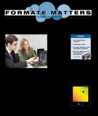
- 1. In a world of diminishing resources how to do more with less? Whether in business or in our privatelivesthisisalwaysanimportantquestion. In a nutshell, this is what eco-efficiency is all about: identifying those products and manufacturing processes that most closely align with the tenets of sustainable develop- ment. The term ‘eco-efficiency’ was first coined in 1992 by the World Business Council for Sustainable Development and is based on the concept of fulfilling the economic, environmental and social requirements of today’s society without adversely affecting the development potential of future generations. Critical aspects of eco-efficiency are: • Reduction in use of material and energy • Reduction in dispersion of toxic materials • Increased product durability • Increased service intensity of goods and services • Minimisation of life cycle costs Economics and ecology One of the first and possibly most well-known methodologies for quantifying sustainability is BASF’s Eco-Efficiency Analysis. Since 1996, this methodology has been used in more than 400 studies for the likes of Bosch Siemens Hausgeräte, Unido, Wella, Bündnis 90/Die Grünen (German Green Party), Environmental Ministry Rhineland-Palatinate and BASF itself. These organisations use the results as a basis for strategic decision-making and/or marketing. The Eco-Efficiency Analysis developed by BASF compares the life cycles of products or manufacturing processes by analysing ecological and economic data. The ecological analysis is based on a life-cycle assessment, which records all relevant emissions, material and energy flows through the product’s life cycle from cradle to grave, including a CO2 balance (carbon footprint). Environmental impact categories taken into account during the full ecological analysis are energy use, raw material consumption, land use, air and water emissions, solid waste levels, toxicity potential and risk potential. The ecological factors comprise one side of the equation. On the other side are the economics. BASF uses a life cycle costing calculation, which goes further than cost of purchase to include costs attached to product use, such as energy, maintenance and disposal costs. When the full study is complete the products’ or processes’ eco-efficiency can be clearly judged against one another. Comparing heavy brines Dr. Xavier Sava, Product Development Manager at BASF, commissioned the brine study on behalf of his company: “An eco-efficiency analysis is always begun by defining a customer benefit. In this case, it was ‘the completion of an average HPHT gas well in the North Sea’. From the data we gathered this brought us to a brine density of 1.85 s.g. (15.44 ppg), which gave us two clear-brine alternatives – formates and bromides, or specifically, blends of cesium/potassium formate and zinc/calcium bromide,” he says. The study itself was conducted by BASF’s Eco-Efficiency unit. Dr. Anahí Grosse-Sommer is responsible for the work. “We took into account all upstream and downstream environmental factors and costs, including production and use of brines and additives, emissions and end-of-life treatment within the stringent regulatory regime of the North Sea”, she explains. “The results show that formate brines are significantly more eco- efficient than bromide brines with both cost and environmental-impact factors in their favour. Formate brines score well on system costs, lower toxicity potential and critical emission levels. The waste category is particularly problematic for bromide brines. Large amounts of zinc bromide-contaminated solids and well water have to be shipped to shore, treated and landfilled as toxic waste,” says Grosse-Sommer. “Formate brines clearly offer the most sustainable solution,” says Sava. “Although we do need to recognise that to achieve a 1.85 s.g. brine you need to use somewhat more formate salt than bromide salt, so over- all material consumption is higher with formates”, he states. The conclusions from this study are clear, but it doesn’t stop there. Further work is planned for this year when clear completion brines will come under the eco-efficiency spotlight again, but this time for other scenarios involving different geographic areas and fluid densities. BASF shines the spotlight on the eco-efficiency of formate brines BASF, the world’s largest chemical company, announces conclusions from a detailed investigation into the eco- efficiency of high-density completion brines. The two products put under the spotlight by BASF were formate brine and bromide brine. 2 The revolutionary ‘Colonel’ 2 Outwardly mobile 3 Formate designer fluids strengthen wellbores 4 Spot the difference and win a SkyScout Planetarium INSIDE F O R M A T E M A T T E R S Issue no. 5 – February/March 2010 News and opinion from Cabot Specialty Fluids www.formatebrines.com LowHighEnvironmentalimpact(norm.) LowHigh Costs (norm.) High eco-efficiency Low eco-efficiency Formate brineBromide brine In the set scenario formate brine is more eco-efficient than bromide brine Dr. Xavier Sava (left) and Dr. Anahí Grosse- Sommer of BASF review the study’s results 5 to win!
- 2. 2 FORMATE MATTERS Issue no. 5 – February/March 2010 Cabot Specialty Fluids improves its ability to re-densify cesium formate in remote locations with its newly commissioned mobile evaporator. The mobile evaporator is currently on location in Kazakhstan where Cabot is contracted to supply cesium formate brine for HPHT wells in the vast Kashagan oil field. Delivering and maintaining correct density is essential for any completion operation using any brine. As water contamination often dilutes the brine, density adjustments must be made regularly when the brine is used in multiple wells. Increases are achieved by adding cesium formate powder or high-density ‘spike’, or through water evaporation. Often, the scale of operation and degree of contamination dictate the optimum process. In North Sea offshore operations, brine is normally shipped back to one of Cabot’s reclamation centres for treatment. In Kazakhstan , the brine can now be redensified on site with the mobile evaporator – a principle that can be applied to most remote offshore or onshore fields to increase operational effectiveness. The unit’s strong metal frame, similar in size to a 20-foot ISO container and certified to DNV CN2.7-1, means the mobile evaporator is easily lifted and transported to its next assignment. Malcolm Cook, Regional Manager, explains how the mobile evaporator works: “The unit operates under a partial vacuum, which both drives the process and reduces the boiling temperature of cesium formate. Dilute cesium formate is sucked into the evaporator and passed through a heat exchanger, where it exchanges heat with the refined cesium formate leaving the system. It then enters a continuous circulating loop where an immersion heater further raises the diluted brine’s temperature until the boiling point is reached and water ‘flashes off’ as vapour into a separator pot. The water vapour is pulled by the vacuum through air blast condensers and pumped out of the system. This process continues until the cesium formate reaches its designated weight and is also pumped out. When this happens more dilute brine is drawn in and the process continues automatically.” Outwardly mobile Dick Wyer New SH&E Manager Dick Wyer (44) is appointed SH&E/QMS Manager at Cabot Specialty Fluids’s Head Office in Aberdeen. Dick comes from Weatherford UK where, as a QHSSE Advisor, he held responsibility for the Wireline, Rental and Pressure Control Business units. Prior to this, he worked as senior instructor on construction plant, material handling, lifting equipment and general HSE issues for eleven years after leaving the British Army. Dick is married to Anne and enjoys camping, canoeing, mountain biking and DIY in his spare time. He also participates in the BT National Swimathon every year when time permits. Jason Littleworth Jason joins Cabot team Jason Littleworth (36) joins Cabot Specialty Fluids as a Senior Fluids & Completions Engineer. Jason has over 18 years’ experience in the oil and gas industry, training first with Halliburton as a Fluids Engineer and later gaining valuable experience from onshore and offshore projects worldwide. For the last eight years, he has worked as an independent consultant specialising in field testing of new products and training of local manpower. When not working he enjoys sailing, skiing, diving and eventing on his Dutch warm- blood sport horse Eskobar. Jason lives in Suffolk, England with his partner Sarah. PEOPLE “The mobile evaporator increases Cabot Specialty Fluids’s recycling capability”, says Malcolm Cook, Regional Manager at Cabot Specialty Fluids, shown here with the unit before shipment to Kazakhstan Just last year we saw the 150th anniversary of the first modern oil well drilled on US soil by Edwin ‘Colonel’ Drake. The story goes that Drake – who wasn’t a colonel at all, but an ex railway conductor – was employed by Seneca Oil to investigate oil seeps on its land in Titusville, Pennsylvania. Prospectors in search of water had drilled here before, but had been hampered by oil that flowed into their wells instead. Drake first began work on his groundbreaking well in 1858, but soon ran into difficulties. At five metres (16 ft.) the hole started to collapse. Undeterred, Drake devised a jointed cast iron pipe that was driven into the ground until it struck bedrock. Steam- powered drilling tools inserted in the drive pipe did the rest. At the end of the day on the 27th August 1859 the bit hit a crevice. When the driller returned to work the next day he was met by the sight of crude oil rising in the hole. Despite his critics (the locals had named his well ‘Drake’s Folly’) and Seneca withdrawing support, Drake won the day. His pioneering method of employing a drive pipe to protect the drilling process was revolutionary and is still used to this day. The revolutionary ‘Colonel’ DID YOU KNOW? Drake’s well drilled in 1858/59 was the first with a drive pipe. The ‘Colonel’ is on the right Photo:©BettmanN/Corbis
- 3. Issue no. 5 – February/March 2010 FORMATE MATTERS 3 Early production of hydrocarbons from HPHT reservoirs while still drilling development wells has the undesirable effect of lowering reservoir pressure. This in turn creates a convergence between pore pressure and fracture pressure in the reservoir and reduces fracture gradient. In such an environment it is easy for overbalanced drilling fluids to fracture weaker elements of the formation, leading to massive mud losses and loss of well control. This was the situation faced by Statoil ASA after drilling nine wells in the Kvitebjørn HPHT gas condensate field, offshore Norway. On the last conventionally drilled well, 34/11-A-2, 140–170 bar of depletion was encountered and massive fluid losses were experienced. The problem was so serious that production operations had to be temporarily shut down in order to avoid further pressure depletion of the reservoir. At this time, there were six further development wells left to drill. The operator solved this problem by intro- ducing two new technologies for drilling depleted reservoirs1 : 1. Managed Pressure Drilling (MPD) MPD is a technique that uses a reduced mud weight and surface controlled back- pressure to manipulate the down-hole pressure profile to keep within the narrow ‘drilling window’. 2. Fracture Gradient Enhancement (FGE) or Stress Caging FGE is achieved by use of a drilling fluid that strengthens the pressure depleted (weakened) sand formations by creating stabilised short fractures that increase the hoop stresses around the wellbore. The fractures are made stable by packing them with special-sized particles and sealing off the mouth of the fracture with an impermeable filter cake2 . Such fluids are commonly referred to as ‘designer fluids’. Designer fluid in Kvitebjørn Kvitebjørn development wells 34/11 – A-13 T2 and 34/11 – A-12 were successfully drilled in 2007 using the enhanced MPD system, including a formate designer fluid. The fluid was based on 1.81 s.g. / 15.11 ppg cesium formate brine containing a blend of calcium carbonate, graphite and nut plug1 . The fluid was designed to contain the optimum particle blends and size distributions to plug the fractures and formation pores. In order to maintain the formation strengthening effect, the particle size distribution (PSD) of the designed blend had to be monitored and maintained during drilling and fluid circulation. This required a reliable method of monitoring PSD during drilling. In Kvitebjørn, Statoil has used an on-line particle size monitoring system with Focused Beam Reflectance Measurement (FBRM) for remote real-time PSD monitoring3 . The improved system measures not only size distribution like most methods, but also particle concentration. The solids-free nature of formate brines can benefit FBRM by helping to ensure accurate measurement and control of particle size distribution and concentration. Since these first field trials in 2007 a further two HPHT wells (A-03 and A-09 T2) have successfully been drilled in Kvitebjørn using MPD and designer formate fluids. This type of FGE ‘designer fluid’ based on brine would be useful for strengthening well bores in deepwater fields where low fracture gradients are prevalent and lost circulation incidents are commonplace4 . References 1. Syltøy, S., et al: “Highly Advanced Multitechnical MPD Concept Extends Achievable HPHT Targets in the North Sea”, SPE/IADC 114484, 26–29 January 2008. 2. Aston, M.S., et al: “Drilling Fluids for Well- bore Strengthening”, SPE/IADC 87130, 2–4 March 2004. 3. Ronaes, E., et al: “Remote Real Time Monitoring of Particle Size Distribution in Drilling Fluids During Drilling of a Depleted HTHP Reservoir”, SPE 125708, 26–28 October 2009. 4. Van Oort, E., et al: “Avoiding Losses in Depleted and Weak Zones by Constantly Strengthening Wellbores”, SPE 125093, 4–7 October 2009. The particle blend and size distribution of the designer fluid were optimised to plug fractures and formation pores Increasing hoop stresses around the well bore by creating short stabilised fractures Formate designer fluids strengthen wellbores Formate technical Manual 8–10 June SPE International Oil & Gas Conference and Exhibition (IOGCEC), Beijing, China Building knowledge It just keeps on coming. Two new chapters have been added to the Formate Technical Manual since our last announcement in July. This time the manual’s author, Siv Howard, has focused on hydrate inhibition (Section B13) and fluid testing and property maintenance (Section C2). In addition there are updates to several sections, so it pays to visit the web- site regularly at www.formatebrines.com/ manual or mail a request to formatemanual@ cabot-corp.com. New technologies help Statoil drill into a depleted reservoir in a challenging North Sea HPHT field. Section B13 Hydrate Inhibition B13.1 Introduction .......................................................................................... 2 B13.2 Hydrate inhibition by formate brines .................................................... 2 B13.3 HET measurements in formate brines ................................................ 3 13.3.1 HET measurements with GoM gas ................................................... 3 13.3.2 HET measurements with Marnock North Sea gas ........................... 4 13.3.3 HET measurements with methane gas ............................................ 5 B13.4 Recommendations ............................................................................... 5 References ...................................................................................................... 5 The Formate Technical Manual is continually updated. To check if a newer version of this section exists please visit www.formatebrines.com/manual COMPATIBILITIES AND INTERACTIONS Section C2Fluid Testing and Property MaintenanceC2.1 Fluid testing procedures...........................................................................2 C2.1.1 Introduction.........................................................................................2 C2.1.2 pH.......................................................................................................2 C2.1.3 Density ...............................................................................................2 C2.1.4 Solids analysis of formate fluids .........................................................4 C2.1.5 Total hardness (Ca + Mg ) ..............................................................4 C2.1.6 Calcium (Ca ) ....................................................................................5 C2.1.7 Dissolved carbonate and bicarbonate (pH buffer) content................5 C2.2 Property maintenance and adjustment...................................................7 C2.2.1 Introduction ........................................................................................ 7 C2.2.2 Density............................................................................................... 7 C2.2.3 Contamination ...................................................................................8 C2.2.4 pH maintenance................................................................................9 C2.2.5 Carbonate / bicarbonate (buffer) maintenance ................................9 C2.2.6 Calcium carbonate maintenance ......................................................9 C2.2.7 Polymer maintenance.......................................................................10 C2.3 Performance enhancement and problem solving................................. 10 C2.3.1 ROP enhancement............................................................................10 C2.3.2 Hole cleaning and hydraulics............................................................ 11 C2.3.3 Fluid loss, rheology, and gelling problems........................................ 11 C2.3.4 Foaming............................................................................................ 11 C2.3.5 Erratic gas readings ......................................................................... 11 References ......................................................................................................11 The Formate Technical Manual is continually updated. To check if a newer version of this section exists please visit www.formatebrines.com/manual FORMATE FIELD PROCEDURES AND APPLICATIONS MEET US AT
- 4. 4 FORMATE MATTERS Issue no. 5 – February/March 2010 Formate brines are traditionally buffered with a mixture of water-soluble carbonate and bicarbonate salts. The ratio of carbonate to bicarbonate salt concentration determines the pH at which the brine is buffered, while the carbonate concentration determines the brine’s ‘buffer capacity’. This buffer system helps to maintain brine pH at the desired working level and controls corrosion in the event of an influx of acid gases into the well bore while the brine is not in circulation. The buffer system also provides some important secondary benefits, including protection of polymers, reduction in formate decomposition rates and the absorption of influxes of toxic H2 S gas. Given the importance of a competent carbonate/bicarbonate buffer to the proper functioning of formate brines it is essential that users have access to a simple field method for monitoring the brines’ buffering capability. Such a method has to provide measurements of the concentrations of soluble carbonate and bicarbonate in formate brines, regardless of the brine density and composition. And it has to be simple enough to use in the field laboratory where sophisticated analytical equipment is generally unavailable. Unfortunately the standard API RP 13B-1 (1997) method for measuring alkalinity in drilling fluids does not work in formate brines as it requires a titration to pH = 3.1. Formate brines have inherent pH buffer capabilities that make it impossible to titrate the brine down to such a low pH value. The renowned Garret Gas Train (GGT) method is little better, being unable to differentiate between carbonate and bicarbonate. Faced with this problem, researchers in Cabot Specialty Fluids have developed a novel method for measuring buffer levels in formate brines. The methodology only requires an accurate determination of the formate brine pH with a pH probe, combined with standard phenolphthalein titration to pH = 8.2. It exploits the relationship between pH and carbonate/bicarbonate ratio in the brine (see graph), which is independent of absolute concentrations of carbonate and bicarbonate and does not depend on type or concentration of formate brine. The method has already been thoroughly tested in the laboratory and is currently being validated in the field. For details of the new method please consult section C2 of the Formate Technical Manual available at www.formatebrines.com/manual. Ref.: Howard, S. and Downs, J.D.: “Formate Brines for HPHT Well Control – New Insight into the Role and Importance of the Carbonate/ Bicarbonate Additive Package,” SPE 121550, April 2009. Technical Forum Spot the difference “ Only two things are infinite, the universe and human stupidity, and I’m not sure about the former.” Albert Einstein, scientist and genius, 1879–1955 AND FINALLY… New field method for monitoring buffer concen- trations in formate brines Sign up for your free subscription! If you would like to receive Formate Matters please send an email to formatematters@cabot-corp.com or call (44) 1224 897229. For further information please contact Cabot Specialty Fluids Ltd., Cabot House, Hareness Circle, Altens Industrial Estate, Aberdeen. AB12 3LY. UK. T: (44) 1224 897229. E: formatematters@cabot-corp.com NOTICE AND DISCLAIMER. This newsletter is designed to provide information of a general nature and is not intended as a substitute for professional consultation and advice in a particular matter. The opinions and interpretations expressed within are those of the author only and may not reflect those of other identified parties. Cabot Specialty Fluids Ltd. does not warrant the accuracy and completeness of this newsletter, nor endorse or make any representations about its content. In no event will Cabot Specialty Fluids Ltd., Cabot Corporation or any of their subsidiaries, affiliates, officers, directors or employees be liable for any damages whatsoever arising out of the use of or reliance on the contents of this newsletter. © 2010 Cabot Corporation, M.A.-U.S.A. All rights reserved. CABOT is a registered trademark of Cabot Corporation. Win a SkyScout Planetarium Do you have an eye for detail? Let’s see shall we? Although the two cartoons pictured above look the same, there are five differences between them. Once you think you’ve found the differences, either scan the marked-up cartoon or write them down and send us your answer. The first five with the correct answers taken randomly from the entrants list win a hand held SkyScout Planetarium from Celestron, which identifies over 6,000 celestial objects at the touch of a button when aimed at any section of the night sky. Best of luck! Please send your entry to formatematters@ cabot-corp.com or fax (44) 1224 870089 by 1 May 2010. Congratulations to all those who solved the anagrams in the last issue of Formate Matters. The lucky winners are: John Kozicz (Transocean), John P. Parker (Q’Max America), Paul Francis (Shell), Jeremy Rhodes (Nexen) and Kevin Meads (Scomi Oiltools). Answers are below. I SAFE COMMUTER = CESIUM FORMATE PUSH RIGS HERE = HIGH PRESSURE HUGER HEAT PERMIT = HIGH TEMPERATURE I FIND DULL GIRL = DRILLING FLUID BIONIC PETROL MEN = COMPLETION BRINE INVENTED FRUIT LION = INTERVENTION FLUID Printed on recycled paper 18 16 14 12 10 8 6 4 2 0 8.5 9.0 9.5 10.0 10.5 11.0 R=[CO3 2- ]/[HCO3 - ] pH Water NaFo KFo At the sports day, cesium formate brines handlers had a natural advantage over their zinc bromide rivals Relationship between the carbonate-to-bicarbonate ratio and pH in buffered deionized water and sodium and potassium formate brines