1. BEND TOOLING INC.: Rotary-Draw Tube-Bending Tools ~ Die Sets ~ Mandrels ~ Wipers ~ Mandrel-
Bending Tools
L-N
Home | Technical Information | Intro
A-B | C-D | E-K | L-N | O-Q | R-S | T-Z
laminated tubing — See double-wall tubing.
length -- The horizontal dimension of a rotary-draw bending clamp die or pressure die parallel to the
cavity of the die block; the dimension of such a block from its leading face to its trailing face; the
dimension of a such a block lying in the plane of bend and perpendicular to block's reach corresponding
to the Y-axis of the tube-bending machine. Usually the cavity length of clamp die or a pressure die is
the same as the block length, but they can differ in the case of a notched die with a block length greater
than the cavity length. For example, most models of rotary-draw tube-bender have a minimum block
length for mounting purpose, but the cavity length must be shorter than that minimum length to
accommodate the restrictions of the part to be bent (typically a multi-bend part with a short mid-
tangent). So attention must be paid to specifying the length of clamp dies and pressure dies in these
situations. See height and reach.
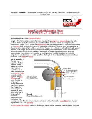
line of tangency —
The line that
separates the bent
from the unbent
portion of the tube;
more properly
understood as a
plane perpendicular
to the plane of bend
which divides the
arc from the back
tangent of the
tube. The line of
tangency is
distinguished from
the point of bend in
that the point of
bend is region of
material on both
sides of the line of
tangency that
becomes
plasticized under
the force of the
bending process. The line of tangency is geometrical entity, whereas the point of bend is a physical
region of the tube. See geometry.
In rotary-draw tube-bending the line of tangency is fixed in space; the tubing material passes through it
2. as it is bent. In compression bending, the line of tangency sweeps along the radius of the bend die as
the pressure die presses the tubing material into the cavity of the bend die. In press bending, two lines
of tangency sweep away from a central starting point as the ram die pushes the tubing material through
a pair of wing dies.
Therefore, the key to the superiority of the rotary-draw method of tube-bending is that a fixed line of
tangency allows for the fixturing of tools both inside and outside and all around the point of bend to
control the flow of material.
[CLICK HERE FOR THE ROLE OF THE LINE OF TANGENCY IN THE 4-STEP SET-UP PROCEDURE]
link — A joint-like component of a mandrel assembly which attaches balls to each other and to the
nose of the mandrel shank. The link originates from a segmented tool patented in the 1890's to form
the spouts of tea kettles and underwent considerable refinement until the late 1950's with the
introduction of the universally flexing H-style link. The H-style link remains the predominant style today
with the only major improvement being the development of the single-piece poppet variety in the late
1980's.
An alternative to link construction of a mandrel assembly is cable construction. The mandrel (or insert)
link, center link, and end link are replaced by a cable which strings a series of balls together. One end
of the cable is anchored inside the mandrel shank and the other is capped with a small ball or plug. A
spring mounted over the anchor usually provides the tension that prevents the cable from drooping
under the weight of the balls. Although cable construction overcomes the inherent weaknesses of the
H-style link design at the extreme ends of its range of performance, cables lack the durability, easy
replacement of components, and reliability in high production of links. See mandrel link, center link,
and end link.
[CLICK HERE FOR A TECHNICAL ARTICLE ON THE ADVANTAGES OF POPPET LINKS]
[CLICK HERE FOR LINK PRODUCT INFORMATION]
lip — The extension of the bend die cavity past the vertical centerline of the tube which is the defining
feature of the captive-lip cavity design. The typical length of this lip is 6% of the tube diameter. The no-
lip cavity design is actually a negative lip; the mating face of the cavity is relieved from the vertical
centerline of the tube usually by
1% of the tube diameter. See
cavity.
mandrel — 1. Short for mandrel
assembly, this tool is a part of the
rotary-draw tube-bending
process. It controls the flow of
plasticizing material at the point of
bend in order to maintain the
shape of tube as it sets into the arc
of the bend. If the tube wall is
thick enough relative to the overall
size of the tube or if the
specifications are not too severe
(e.g., shallow depth of bend or a
large "D" bend radius), then a
mandrel may not be necessary,
because the force of the bend is
not sufficient to buckle or collapse the tube wall at the point of bend. However, if the wall factor of a
tube exceeds 20, a mandrel is needed in most instances.
The key to effective use of the mandrel is to set its nose so that it supports as much of the point of bend
as possible. This ensures that the vertical cross-section of the arc of the tube bend, while it is in a
plastic state, will take the shape of the nose as the tubing material is drawn over it. This plastic region
3. of the tube bend extends both behind and ahead of the line of the tangency, therefore, the mandrel
nose must be set forward of the line of tangency into the arc of the tube bend in almost all cases. (See
entry under "line of tangency" for further information on how a mandrel performs in the rotary-draw
process.)
The limiting factor of this forward placement is the point where the outboard line of the mandrel
intersects with the tube wall of the outside radius; in other words, the point where the mandrel nose
would literally stick out past the bend. The location of this point can be determined by formula
developed from the Pythagorean thereom. Generally it is advisable to locate the nose (excluding the
nose radius) about the two-thirds of the distance between this point and the line of tangency. This will
allow for slight flattening of the tube's cross-section at the outside radius, which unavoidably occurs
because of the tension of the draw, without intersecting the mandrel nose.
2. The mandrel body or shank, particularly in reference to a non-inserted mandrel assembly.
3. A plug, i.e., a mandrel that does not require a ball assembly.
[CLICK HERE FOR MANDREL SET-UP INFORMATION]
[CLICK HERE FOR MANDREL PRODUCT INFORMATION]
mandrel assembly — Often referred to loosely as the mandrel, which see, a complete mandrel
assembly consists of: [1] a mandrel body, [2] a mandrel nose insert, [3] a mandrel link or insert link, [4]
a mandrel screw, and, if necessary, [5] a ball sub-assembly. A non-inserted mandrel assembly,
sometimes called an "aircraft type" or "aircraft quality" mandrel assembly, does not include the second
component, the nose insert.
mandrel ball, mandrel (ball) segment — A component of a mandrel assembly. See ball.
mandrel body — The section of the mandrel assembly which connects the mandrel sub-assembly to
the mandrel rod of a tube-bending machine. In an inserted mandrel assembly, the mandrel body does
not include a nose, which is a separate detachable component held to the body by means of the insert
link and the mandrel screw. Therefore, the mandrel body in this case is a relatively long-lived
4. component that needs to be replaced only after extreme wear.
The mandrel body of a non-inserted mandrel assembly has an integrated nose to control the flow of
material at the point of bend. Thus, such a mandrel body wears out when the nose does and is
relatively short-lived compared to that of an inserted assembly. Because a mandrel body cannot be
reconditioned for re-use in the same tube-bending application (it is occasionally possible to re-machine
it for another application), it must be discarded after its nose wears out. This is its primary
disadvantage. However, a non-inserted mandrel body remains the tool of choice for those applications
with a high rigidity factor (for example, non-round tubing or compression-resistant materials like Inconel)
because its strength is a more important consideration than tool life.
Technically a mandrel body is not a plug. A plug is a complete, fully-functioning mandrel assembly,
whereas, a mandrel body is a component of a mandrel assembly (although in the case of a non-
inserted plug, the mandrel body is the only component of that assembly).
mandrel flats — The wrench flats milled onto a mandrel body which facilitate screwing the mandrel
assembly onto the mandrel rod of the tube-bending machine. These flats are typically on the end of the
mandrel body opposite of the nose, although they occasionally appear in the middle of the body. The
specification for wrench flats usually varies with the threading of the mandrel body to ensure that the
cross-section between a flat and the major diameter of the thread is as thick as possible.
mandrel insert — Same as mandrel nose insert, which see.
mandrel link — 1. The link connecting a ball sub-assembly to a non-inserted mandrel body. Because
there is no mandrel nose insert, a mandrel link lacks the shoulder that is characteristic of the insert
link. Sometimes called a "shank link".
2. An insert link.
mandrel nose — Either the nose insert of an inserted mandrel body or the nose portion of a non-
inserted mandrel body, both function in the same manner as the "working" end of the mandrel body. It
is positioned at the point of bend to control the flow of material and so takes the brunt of the wear in a
mandrel assembly.
mandrel nose insert — The replaceable nose section of an
inserted mandrel body. It is designed as a relatively inexpensive
component of a mandrel assembly to be detached from the mandrel
body when it is worn out and disposed of. Another feature is that a
mandrel nose insert of one material can be swapped with one of
another material so that the same mandrel body can be used for
different tubing materials.
[CLICK HERE FOR MANDREL NOSE INSERT PRODUCT INFORMATION]
mandrel overall length — The overall length of the shank of a mandrel assembly — i.e., the length of
a non-inserted mandrel body or the combined length of a mandrel nose insert and mandrel body. This
specification does not include the ball assembly and typically varies according to set standards relative
to tube diameter. However, overall length may be increased and decreased from the standard to
accommodate special considerations involving the reach of the mandrel rod or the collet of a tube-
bending machine.
mandrel shank — Similar to the term "mandrel body", which
see. Refers to both a non-inserted mandrel body or the combination
of a mandrel nose insert and mandrel body.
mandrel sub-assembly — A ball sub-assembly, which see, plus a
mandrel nose insert. A one-ball mandrel sub-assembly includes the
following components: [1] mandrel nose insert, [2] insert link, [3]
mandrel ball, and [4] end link. Multiple-ball mandrel sub-assemblies
include a mandrel and a center link for each additional ball of the
5. assembly.
mandrel thread — All mandrel bodies have internal threads at the end opposite of the nose in order to
attach the mandrel assembly to the mandrel rod. The mandrel thread specification typically varies with
tube diameter. Although there is no official standard, some common relationships have developed over
time for non-metric tube-bending machines. For tube diameters around 1", 1/2"-13 UNC threads are
typical, from about 1.25" to 1.375" 5/8-11 UNC, and from about 1.5" to 3" 1"-8 UNC.
mechanical tubing — Tubing specified for structural or mechanical purposes as opposed to the
containment of liquids and gasses. Most commonly mechanical tubing is steel. Compare pressure
tubing.
mid-tangent — A tangent located between two bends made on the same section of tubing. Compare
end tangent; also see tangent. The mid-tangent becomes an important consideration in tool design and
machine process if its length is shorter than the recommended clamp length for the tube-bending
application. In those instances when a short mid-tangent compromises the optimal clamp design, a
conflict arises between ease-of-bending and bend quality that often is not resolved unless compound
clamps are used. See the entries under clamp die and compound clamp for a full treatment of this
issue.
mild steel — Low carbon unalloyed steel used for tubing that is relatively easy to form compared to
alloy steels, high-carbon steels, and stainless steels. Aluminum-bronze mandrel and wiper tooling is
usually recommended for working with mild steel tubing. Hard-chromed mandrel and untreated steel
wiper tooling is sometimes preferred because of longer tool-life; however, extended tool-life with these
materials is dependent upon continuous and heavy lubrication of the tubing material and tooling
surfaces. See steel.
minimum wall thickness — A post-bend specification controlling wall thinning which sets the minimum
wall thickness allowed for the finished part. In rotary-draw tube-bending wall thinning is unavoidable in
the extrados, which see, but it can be mitigated by proper placement of the mandrel nose relative to the
line of tangency, using the least direct pressure the application requires, and using assist pressure to
feed material from the trailing tangent into the extrados. See wall thinning.
mounting bracket — Same as hanger bracket, which see.
mounting pattern — The specification of the number of screw holes, center-to-center location of those
holes, location of the overall pattern, and threading of the mounting holes of a wiper die. Certain
patterns are quite common, such as two 3/8"-16 mounting holes on 1.5" centers for smaller wiper dies
(under 3" tube diameter) and two 1/2"-13 mounting holes on 2" centers for larger wiper dies (over 3"
tube diameter).
mounting pin — The pin attached to the clamp slide of a tube-bending machine upon which a clamp
die hanger bracket is located. This pin-type of clamp die mounting is standard on older models of Pines
bending machines. The T-key type of mounting is most common today.
neutral axis — The line separating the regions of compression (intrados) and elongation (extrados) of
the tube wall during the bending process. Because the intrados and extrados extend into the leading
and trailing tangents of a bend, so does the neutral axis which widens into an inactive zone at these
extremes. Contrary to common misconception, the neutral axis is not the centerline radius, which is a
geometric entity. The neutral axis lies inboard of the centerline radius. See geometry for illustration.
nitriding — A type of case-hardening for alloy and tool steels in which a surface is hardened by an
infusion of nitrogen. One advantage nitriding had over carburizing, which adds carbon to a steel
surface, is that quenching is not need to complete the hardening process, thus eliminating one source
for dimensional distortion. However, the nitriding process is an excellent treatment for alloy steels
which have good shock-resistant qualities.
no-lip — A common type of cavity design for tube-bending dies which is true to the size and shape of
the tube to be bent (with minor allowances) and a bend die lip extending over the centerline of the
![as it is bent. In compression bending, the line of tangency sweeps along the radius of the bend die as
the pressure die presses the tubing material into the cavity of the bend die. In press bending, two lines
of tangency sweep away from a central starting point as the ram die pushes the tubing material through
a pair of wing dies.
Therefore, the key to the superiority of the rotary-draw method of tube-bending is that a fixed line of
tangency allows for the fixturing of tools both inside and outside and all around the point of bend to
control the flow of material.
[CLICK HERE FOR THE ROLE OF THE LINE OF TANGENCY IN THE 4-STEP SET-UP PROCEDURE]
link — A joint-like component of a mandrel assembly which attaches balls to each other and to the
nose of the mandrel shank. The link originates from a segmented tool patented in the 1890's to form
the spouts of tea kettles and underwent considerable refinement until the late 1950's with the
introduction of the universally flexing H-style link. The H-style link remains the predominant style today
with the only major improvement being the development of the single-piece poppet variety in the late
1980's.
An alternative to link construction of a mandrel assembly is cable construction. The mandrel (or insert)
link, center link, and end link are replaced by a cable which strings a series of balls together. One end
of the cable is anchored inside the mandrel shank and the other is capped with a small ball or plug. A
spring mounted over the anchor usually provides the tension that prevents the cable from drooping
under the weight of the balls. Although cable construction overcomes the inherent weaknesses of the
H-style link design at the extreme ends of its range of performance, cables lack the durability, easy
replacement of components, and reliability in high production of links. See mandrel link, center link,
and end link.
[CLICK HERE FOR A TECHNICAL ARTICLE ON THE ADVANTAGES OF POPPET LINKS]
[CLICK HERE FOR LINK PRODUCT INFORMATION]
lip — The extension of the bend die cavity past the vertical centerline of the tube which is the defining
feature of the captive-lip cavity design. The typical length of this lip is 6% of the tube diameter. The no-
lip cavity design is actually a negative lip; the mating face of the cavity is relieved from the vertical
centerline of the tube usually by
1% of the tube diameter. See
cavity.
mandrel — 1. Short for mandrel
assembly, this tool is a part of the
rotary-draw tube-bending
process. It controls the flow of
plasticizing material at the point of
bend in order to maintain the
shape of tube as it sets into the arc
of the bend. If the tube wall is
thick enough relative to the overall
size of the tube or if the
specifications are not too severe
(e.g., shallow depth of bend or a
large "D" bend radius), then a
mandrel may not be necessary,
because the force of the bend is
not sufficient to buckle or collapse the tube wall at the point of bend. However, if the wall factor of a
tube exceeds 20, a mandrel is needed in most instances.
The key to effective use of the mandrel is to set its nose so that it supports as much of the point of bend
as possible. This ensures that the vertical cross-section of the arc of the tube bend, while it is in a
plastic state, will take the shape of the nose as the tubing material is drawn over it. This plastic region](data:image/gif;base64,R0lGODlhAQABAIAAAAAAAP///yH5BAEAAAAALAAAAAABAAEAAAIBRAA7)