SlideShare une entreprise Scribd logo
1  sur  9
Télécharger pour lire hors ligne
Everyone has heard of it, everyone has seen or experienced it. So why is there so much mystery
surrounding equipment “stall”. Stall can most easily be defined as a condition in which heat transfer
equipment is unable to drain condensate and becomes flooded due to insufficient system pressure.
What causes stall?
Stall occurs primarily in heat transfer equipment where the steam pressure is modulated to obtain a
desired output (i.e. product temperature). The pressure range of any such equipment ( coils, shell & tube,
etc.…) can be segmented into two (2) distinct operational modes: Operating and Stall
Operating: In the upper section of the pressure range the operating pressure (OP) of the equipment is
greater than the back pressure (BP) present at the discharge of the steam trap. Therefore a positive
pressure differential across the trap exists allowing for condensate to flow from the equipment to the
condensate return line.
Stall: In the lower section of the pressure range the operating pressure (OP) of the equipment is less than
or equal to the back pressure (BP) present at the discharge of the steam trap. Therefore a negative or no
pressure differential exists, this does not allow condensate to be discharged to the return line and the
condensate begins to collect and flood the equipment.
In Figure 2 we can see how this concept applies to a real world application. Assume the following
operating conditions:
DP
Operating
Stall
BP
0 psig
Vacuum
Figure 1
OperatingPressureRangeofEquipment
DP=100 psig
Draining
Stall
BP=15 psig
0 psig
Vacuum
Figure 2
Armstrong Fluid Handling
Understanding and Solving Equipment Stall
AFH-217
2
It is clear that any time the air heating coil
in Figure 3 modulates below 15 psig the
system will fall into a “stall” condition. This
condition is most likely to occur when there
is a light heating load, causing the coil to
operate at a fraction of its capacity and a
fraction of the design pressure
Effects of “stall”
In a stall condition condensate accumulates within the equipment. When equipment becomes flooded by
stalled condensate a variety of problems ranging from minor to catastrophic failure will occur.
Problems associated with stall:
n Inadequate condensate drainage
n Waterhammer (Thermal shock)
n Frozen coils
n Corrosion due to cool condensate and the formation of Carbonic acid
n Poor temperature control
n Short equipment life
n Control valve hunting (system cycling)
n Reduction in heat transfer capacity
Factors contributing to “stall”
Stall happens for a variety of reasons, but it always comes back the fact that there is not always enough
system pressure to return the condensate. The lack of sufficient pressure in the equipment may be caused
by anyone of the following:
n Oversized equipment (excessive surface area)
n Overly conservative fouling factors
n Back pressure at equipment discharge due to elevation or pressure in the line
n Modulating control
n Equipment operating at lower pressures due to light load demands
n Vacuum
Table 1
Design Pressure (DP) = 100 psig
Back Pressure (BP) = 15 psig
Incoming Air Temperature (T1) = -10°F
Exit Air Temperature (T2) = 70°F
Design Condensate Load (DL) = 3,000 lb/hr
Figure 3
3
Many types of heat transfer equipment are susceptible to stall because they are designed with excessive
safety factors built into the design. In attempting to provide an extremely robust heat exchanger,
equipment manufactures and engineers often “over design” equipment which often lends itself to a stall
scenario.
Solutions?
The problems of equipment stall are well known and well documented. Over the years there has been a
variety of so called “solutions” that would all alleviate the stall scenario.
Installation of a vacuum breaker:
Objective:
To relieve a vacuum within equipment allowing for condensate drainage.
Shortcoming:
1. This practice will only help if the condensate is gravity drain to atmosphere, any pressure present at the
discharge of the trap will not allow condensate drainage.
2. Allows undesirable air into the system.
3. Vacuum breakers often fail due to a poorly chosen location downstream of the equipment causing a
build-up of scale/sediment impeding the operation. Such a location may also allow the hydrostatic
pressure of a vertical water column to keep the vacuum breaker closed in a small vacuum.
4. Loss of valuable flash steam
Installation of a safety drain:
Objective:
The use of a second steam trap located above the primary trap which discharges condensate to drain
when the system goes into a stall condition.
Shortcoming:
A significant amount of condensate/flash steam and valuable BTU’s are lost down the drain when the
system is in stall. Stall load may as high as 90% or more of the design load, therefore 90% of the
condensate coming from the equipment goes down the drain
Installation of a positive pressure system:
Objective:
The use of air or other gas to maintain set pressure to ensure a positive pressure differential across the
trap allowing for condensate drainage.
Shortcomings:
Injects a significant amount of undesirable air into the equipment. This large amount of air may cause
multiple problems:
1. Air acts as an insulator thereby decreasing the heat transfer capacity of the equipment.
2. A heavy dependence on air vents to evacuate the air from the equipment.
3. Air vents may be open a significant amount of time allowing for loss of valuable BTU’s.
The Solution
The application of a “closed” system pump trap on your modulating steam equipment can provide the
following benefits:
n Continuous condensate drainage, even in a vacuum
n Eliminates the need for vacuum breakers
n Saves valuable flash steam from escaping into the atmosphere
4
n No need to run expensive vent lines
n Size pump traps on stall load, resulting in smaller pumps and less cost
n No rotating seals, cavitation, or NPSH requirements
n Negligible operating cost
n Longer equipment life
n Reduced corrosion
n Better temperature control
n Reduced maintenance…….and more
The Closed Loop Concept
The closed loop application of a pump trap is based around one basic concept:
To equalize the pressure in the heat exchange equipment and the pump trap thereby allowing condensate
to drain by gravity to the pump trap.
The equalization of pressure is accomplished by:
1. Connecting the vent of the pump trap to the inlet steam side of the equipment or to a condensate
receiver upstream of the pump trap.
2. Placing the steam trap on the outlet side of the pump trap or eliminating the steam trap altogether
(if DP<BP)
Figure 4 shows the appropriate piping configurations for a closed loop pump trap application. Connecting
the vent line of the pump trap to the inlet steam side to the equipment is the preferred method of pressure
equalization if the pressure drop across the heat exchange equipment is ½ psig or less.
If the pressure drop is greater, the vent line of the pump trap should be connected to the condensate
receiver upstream of the pump trap. The vent line must be connected into a vapor space, not into liquid.
(Note: Piping from the equipment should be increased one pipe size and be pitched towards the receiver
to avoid water seal)
In either configuration the vent line should be increased one pipe size if the length is to exceed 6 feet.
Figure 4
5
Equipment Sizing:
The main components to be sized in a closed loop pump trap application are the pump trap and the steam
trap (if necessary).
Pump trap sizing:
One major benefit of using a pump trap in a closed loop system is the ability to size the pump based on the
stall load as opposed to the design load. This will almost always result in a smaller required pump capacity
since the stall load is generally some fraction of the design load. The pump trap can be sized based on the
stall load because:
When the equipment operating pressure (OP) is above the back pressure (BP) the condensate is
discharged into the return line by the positive pressure differential (draining mode). In this mode the pump
trap is inactive, the condensate simply flows through the pump as if it were a piece of pipe.
When the equipment operating pressure (OP) is less than or equal to the back pressure (BP), condensate
is unable to be discharged into the return line due to insufficient pressure and the system goes into stall.
Usually the condensate would accumulate in the equipment, but in a closed loop system the condensate
collects in the pump trap. Once the pump trap is filled to the appropriate level the pump trap is activated
and pumps the stalled condensate through the steam trap and into the return line. Hence the pump trap
only pumps when the system is in “stall” and thereby allowing the pump trap to be sized based on the stall
load as opposed to the design load.
Sizing the steam trap in a closed loop system:
The recommended steam trap for modulating service is generally a Float and Thermostatic (F&T) trap.
The F&T trap is chosen for its continuous drainage, air venting capabilities, and the ability to handle the
high instantaneous loads when used in conjunction with a pump trap in closed loop system.
The steam trap in a closed loop system must be able to handle the demands of the heat exchange
equipment and the instantaneous pumped loads of the pump trap. Therefore the steam trap must be sized
twice, once for the equipment and once for the pump trap.
Sizing the steam trap based on modulating heat exchange equipment.
Sizing the steam trap based on the pump trap
The larger trap from either method is the correct trap to be used in a closed loop system in conjunction with
a pump trap.
Determining Stall Load
Operating parameters of the equipment and system can be graphed on a stall chart to determine two very
critical points:
1. The minimum allowable flow rate before the equipment goes into a stall condition. The stall load is
expressed as a percentage of the design load (assuming T1 is constant).
2. The maximum incoming temperature (T1) before the equipment goes into a stall condition (assuming
flow rate is constant).
Table 2
Operating Pressure Safety Factor
0 - 15 psig 2:1 @ 1/2 psi differential
16 - 30 psig 2:1 @ 2 psi differential
> 30 psig 3:1 @ 1/2 max. pressure differential
Table 3
Operating Pressure Safety Factor
Must handle maximum pressure of
heat exchange equipment
Stall load @ 1/4 psi differential
6
To use the stall chart the following information must is required:
n Design Pressure (DP)
n Back Pressure (BP)
n Incoming Temperature (T1)
n Exiting Temperature (T2)
Using the parameters from Table 1, the stall chart is plotted using the following steps:
1. Plot T1 = -10°F on the vertical axis on the left, then plot T2 = 70°F on the vertical axis on the right and
draw a line to connect the points.
2. Determine the Mean Temperature (MT)= (T1+T2)/2 = (-10+70)/2 = 30°F. Plot MT=30°F on the vertical
axis on the right. Plot the Design Pressure (DP) =100 psig on the vertical axis on the left. Draw a line
to connect points MT and DP.
3. Plot the Back Pressure (BP) = 15 psig on the vertical axis on the left. Draw a horizontal line at BP
across the chart.
4. At the intersection of line BP and line MT/DP drop a vertical line to determine that the stall load
percentage (SL) = 73%
5. At the intersection line T1/T2 and vertical line SL, draw a horizontal line to the left to determine that the
stall temperature (ST) = 13°F
7
Figure 5
8
With the information from the stall chart to critical points can be identified:
1. The Stall Load percentage (SL) indicates the coil is in a stall condition anytime the load drops below
73% of the Design Load (DL). Therefore the maximum amount of condensate being produced when
the coil is in stall is SL x DL = .73 x 3000 lb/hr = 2190 lb/hr. In a closed loop system the pump trap can
be sized on the stall load of 2190 lb/hr instead of the design load of 3000 lb/hr, resulting in a smaller,
less expensive pump trap.
2. The Stall Temperature (ST) = 13°F indicates the coil is in a stall condition anytime T1 is greater than
13°F. Anytime incoming air is warmer than 13°F the coil will not drain condensate with out assistance.
How many days a year is the outside temperature greater than 13°F, almost everyday!!
Knowing the stall load, the pump trap and steam trap for our example in Figure 1 can be
determined.
Pump trap sizing example:
*Assuming 12” fill head and 50 psig steam motive
In an open system the pump trap would be sized for the design load of 3000 lb/hr resulting in the use of a larger
PT-206 pump trap.
Steam trap sizing example:
Based on Pump trap
Based on heat exchange equipment
Both methods selected a 125-J8 steam trap, however if there were a difference the larger trap would be
chosen.
Conclusion
Applications for applying pump traps in closed systems to eliminate problems with stall exist at almost
every facility.
The benefits of using a pump trap in a closed system to solve the problem of “stall” can provide multiple
benefits that reduce maintenance, improve performance, increase equipment life, and provide significant
cost savings in installation and operation.
Table 4
Required Load Motive Pressure Available Back Pressure Pump Trap Model
2,190 lb/hr 100 psig steam 15 psig PT-204*
Table 5
Stall Load Safety Factor Steam Trap Model
2,190 lb/hr
Stall load @ 1/4 psi differential
2,190 @ 1/4 psi differential
F&T 125-J8
Stall Load Safety Factor Steam Trap Model
3,000 lb/hr
3:1 @ 1/2 max. differential
9,000 @ 50 psi differential
F&T 125-J8
9
Figure 6
Armstrong Fluid Handling, Inc., 221 Armstrong Blvd., P.O. Box 408, Three Rivers, Michigan 49093 - USA Ph: (616) 279-3601 Fax: (616) 279-3150
www.armstrong-intl.comAFH- 217 6/00 Printed in U.S.A.

Contenu connexe

Tendances

Ai Ch E Overpressure Protection Training
Ai Ch E Overpressure Protection TrainingAi Ch E Overpressure Protection Training
Ai Ch E Overpressure Protection Training
ernestvictor
 
Multistage-steam-jet-vacuum-ejectors
Multistage-steam-jet-vacuum-ejectorsMultistage-steam-jet-vacuum-ejectors
Multistage-steam-jet-vacuum-ejectors
Tomas Eriksson
 

Tendances (20)

Pressure relief system_design
Pressure relief system_designPressure relief system_design
Pressure relief system_design
 
Relief systems
Relief systemsRelief systems
Relief systems
 
High pressure system- Anaesthesia Machine
High pressure system- Anaesthesia MachineHigh pressure system- Anaesthesia Machine
High pressure system- Anaesthesia Machine
 
How toselecta fanorblower
How toselecta fanorblowerHow toselecta fanorblower
How toselecta fanorblower
 
Pressure Relief Valve Sizing for Single Phase Flow
Pressure Relief Valve Sizing for Single Phase FlowPressure Relief Valve Sizing for Single Phase Flow
Pressure Relief Valve Sizing for Single Phase Flow
 
Steam Condensate Return Stations
Steam Condensate Return StationsSteam Condensate Return Stations
Steam Condensate Return Stations
 
Ai Ch E Overpressure Protection Training
Ai Ch E Overpressure Protection TrainingAi Ch E Overpressure Protection Training
Ai Ch E Overpressure Protection Training
 
Control valves
Control  valvesControl  valves
Control valves
 
Multistage-steam-jet-vacuum-ejectors
Multistage-steam-jet-vacuum-ejectorsMultistage-steam-jet-vacuum-ejectors
Multistage-steam-jet-vacuum-ejectors
 
Rupture Disks for Process Engineers
Rupture Disks for Process EngineersRupture Disks for Process Engineers
Rupture Disks for Process Engineers
 
Cavitation Reduction in Industrial Process Control Valves
Cavitation Reduction in Industrial Process Control ValvesCavitation Reduction in Industrial Process Control Valves
Cavitation Reduction in Industrial Process Control Valves
 
Design and analysis of control valve with a multi stage anti cavitation trim
Design and analysis of control valve with a multi stage anti cavitation trimDesign and analysis of control valve with a multi stage anti cavitation trim
Design and analysis of control valve with a multi stage anti cavitation trim
 
Control Valve Types
Control Valve TypesControl Valve Types
Control Valve Types
 
Steam Thermocompressor Technical Information
Steam Thermocompressor Technical InformationSteam Thermocompressor Technical Information
Steam Thermocompressor Technical Information
 
Psv scenario-and-calculation
Psv scenario-and-calculationPsv scenario-and-calculation
Psv scenario-and-calculation
 
Designer and operator manual dorot
Designer and operator manual dorotDesigner and operator manual dorot
Designer and operator manual dorot
 
Control Valves (THINKTANK®️)
Control Valves (THINKTANK®️)Control Valves (THINKTANK®️)
Control Valves (THINKTANK®️)
 
Cylinders
CylindersCylinders
Cylinders
 
Thermocompressors us
Thermocompressors usThermocompressors us
Thermocompressors us
 
Safety valve in process industry1
Safety valve in process industry1Safety valve in process industry1
Safety valve in process industry1
 

Similaire à Understanding & Solving Heat Transfer Equipment Stall

Condenser in thermal power plants
Condenser in thermal power plantsCondenser in thermal power plants
Condenser in thermal power plants
SHIVAJI CHOUDHURY
 
Boiler doc 08 control application
Boiler doc 08   control applicationBoiler doc 08   control application
Boiler doc 08 control application
Mars Tsani
 
HVAC Preventive maintenance Presentation EVRaju
HVAC Preventive maintenance  Presentation EVRajuHVAC Preventive maintenance  Presentation EVRaju
HVAC Preventive maintenance Presentation EVRaju
Venkata Raju Edarapalli
 
Ca expansion tanks
Ca expansion tanksCa expansion tanks
Ca expansion tanks
trhieufans
 

Similaire à Understanding & Solving Heat Transfer Equipment Stall (20)

Condenser in thermal power plants
Condenser in thermal power plantsCondenser in thermal power plants
Condenser in thermal power plants
 
Barometric condensor
Barometric condensorBarometric condensor
Barometric condensor
 
hvac refragration Pipes size and table
hvac refragration Pipes size and tablehvac refragration Pipes size and table
hvac refragration Pipes size and table
 
Steam distribution system by Varun Pratap Singh
Steam distribution system by Varun Pratap SinghSteam distribution system by Varun Pratap Singh
Steam distribution system by Varun Pratap Singh
 
Review paper on study and implementation of steam traps
Review paper on study and implementation of steam trapsReview paper on study and implementation of steam traps
Review paper on study and implementation of steam traps
 
Steam Blow
Steam BlowSteam Blow
Steam Blow
 
Model 8.1-pressure control
Model 8.1-pressure controlModel 8.1-pressure control
Model 8.1-pressure control
 
Boiler doc 08 control application
Boiler doc 08   control applicationBoiler doc 08   control application
Boiler doc 08 control application
 
Multi Stage Steam Jet Vacuum Systems
Multi Stage Steam Jet Vacuum SystemsMulti Stage Steam Jet Vacuum Systems
Multi Stage Steam Jet Vacuum Systems
 
STEFFO REPORT
STEFFO REPORTSTEFFO REPORT
STEFFO REPORT
 
air evacuation system and lrpv (liquid ring vacuum pump)
air evacuation system and lrpv (liquid ring vacuum pump) air evacuation system and lrpv (liquid ring vacuum pump)
air evacuation system and lrpv (liquid ring vacuum pump)
 
HVAC Preventive maintenance Presentation EVRaju
HVAC Preventive maintenance  Presentation EVRajuHVAC Preventive maintenance  Presentation EVRaju
HVAC Preventive maintenance Presentation EVRaju
 
Understanding Condensate Pumps on a Steam Distribution System
Understanding Condensate Pumps on a Steam Distribution SystemUnderstanding Condensate Pumps on a Steam Distribution System
Understanding Condensate Pumps on a Steam Distribution System
 
Condensate Pumps for industrial steam systems
Condensate Pumps for industrial steam systemsCondensate Pumps for industrial steam systems
Condensate Pumps for industrial steam systems
 
Industrial fan(ID FD Fans)
Industrial fan(ID FD Fans)Industrial fan(ID FD Fans)
Industrial fan(ID FD Fans)
 
Steam Flow Measurement By Dk Singhal
Steam Flow Measurement By Dk SinghalSteam Flow Measurement By Dk Singhal
Steam Flow Measurement By Dk Singhal
 
Condensate Return Solutions.ppt
Condensate Return Solutions.pptCondensate Return Solutions.ppt
Condensate Return Solutions.ppt
 
Ca expansion tanks
Ca expansion tanksCa expansion tanks
Ca expansion tanks
 
Vacuum system
Vacuum systemVacuum system
Vacuum system
 
“Antisurge Protection in action” for Compressors By Prem Baboo.pdf
“Antisurge Protection in action” for Compressors By Prem Baboo.pdf“Antisurge Protection in action” for Compressors By Prem Baboo.pdf
“Antisurge Protection in action” for Compressors By Prem Baboo.pdf
 

Plus de Mead O'Brien, Inc.

Steam Trapping and Steam Tracing Equipment
Steam Trapping and Steam Tracing EquipmentSteam Trapping and Steam Tracing Equipment
Steam Trapping and Steam Tracing Equipment
Mead O'Brien, Inc.
 

Plus de Mead O'Brien, Inc. (20)

Intrusive vs. Non-Intrusive Electric Actuators: Which option is right for you...
Intrusive vs. Non-Intrusive Electric Actuators: Which option is right for you...Intrusive vs. Non-Intrusive Electric Actuators: Which option is right for you...
Intrusive vs. Non-Intrusive Electric Actuators: Which option is right for you...
 
Industrial Boiler and Burner Limit Control Switches
Industrial Boiler and Burner Limit Control SwitchesIndustrial Boiler and Burner Limit Control Switches
Industrial Boiler and Burner Limit Control Switches
 
Metso Neles Flow Control Solutions: Valves, Actuation, and Automation
Metso Neles Flow Control Solutions: Valves, Actuation, and AutomationMetso Neles Flow Control Solutions: Valves, Actuation, and Automation
Metso Neles Flow Control Solutions: Valves, Actuation, and Automation
 
Ashcroft Corrosion Guide
Ashcroft Corrosion GuideAshcroft Corrosion Guide
Ashcroft Corrosion Guide
 
How Your Steam Trap Selection Affects Your Bottom Line Profits: Inverted Buck...
How Your Steam Trap Selection Affects Your Bottom Line Profits: Inverted Buck...How Your Steam Trap Selection Affects Your Bottom Line Profits: Inverted Buck...
How Your Steam Trap Selection Affects Your Bottom Line Profits: Inverted Buck...
 
Steam Trapping and Steam Tracing Equipment
Steam Trapping and Steam Tracing EquipmentSteam Trapping and Steam Tracing Equipment
Steam Trapping and Steam Tracing Equipment
 
Limitorque WG Series Installation, Operation, and Maintenance
Limitorque WG Series Installation, Operation, and MaintenanceLimitorque WG Series Installation, Operation, and Maintenance
Limitorque WG Series Installation, Operation, and Maintenance
 
Metso Neles T5 Series Top Entry Rotary Ball Valves
Metso Neles T5 Series Top Entry Rotary Ball ValvesMetso Neles T5 Series Top Entry Rotary Ball Valves
Metso Neles T5 Series Top Entry Rotary Ball Valves
 
Foxboro IMT23 Transmitter Operation, Configuration, and Calibration
Foxboro IMT23 Transmitter Operation, Configuration, and CalibrationFoxboro IMT23 Transmitter Operation, Configuration, and Calibration
Foxboro IMT23 Transmitter Operation, Configuration, and Calibration
 
Water Cooled Portable Air Conditioners
Water Cooled Portable Air ConditionersWater Cooled Portable Air Conditioners
Water Cooled Portable Air Conditioners
 
VERIS Accelabar Flow Meter
VERIS Accelabar Flow MeterVERIS Accelabar Flow Meter
VERIS Accelabar Flow Meter
 
Limitorque QX Electronic Actuator User Instructions
Limitorque QX Electronic Actuator User InstructionsLimitorque QX Electronic Actuator User Instructions
Limitorque QX Electronic Actuator User Instructions
 
Steam Conservation Guidelines for Condensate Drainage
Steam Conservation Guidelines for Condensate DrainageSteam Conservation Guidelines for Condensate Drainage
Steam Conservation Guidelines for Condensate Drainage
 
Neles NDX Intelligent Valve Positioner
Neles NDX Intelligent Valve PositionerNeles NDX Intelligent Valve Positioner
Neles NDX Intelligent Valve Positioner
 
Hot Water for Industry
Hot Water for IndustryHot Water for Industry
Hot Water for Industry
 
Neles Triple Eccentric Disc Valve, Metal Seated with Flow Balancing Trim
Neles Triple Eccentric Disc Valve, Metal Seated with Flow Balancing TrimNeles Triple Eccentric Disc Valve, Metal Seated with Flow Balancing Trim
Neles Triple Eccentric Disc Valve, Metal Seated with Flow Balancing Trim
 
BIST (Built-in-Self-Test) Features for Electronic Valve Actuators
BIST (Built-in-Self-Test) Features for Electronic Valve ActuatorsBIST (Built-in-Self-Test) Features for Electronic Valve Actuators
BIST (Built-in-Self-Test) Features for Electronic Valve Actuators
 
Automation in Industry: The People Make the Difference!
Automation in Industry: The People Make the Difference! Automation in Industry: The People Make the Difference!
Automation in Industry: The People Make the Difference!
 
A Guide to Instrumentation for Ethanol Fuel Production
A Guide to Instrumentation for Ethanol Fuel ProductionA Guide to Instrumentation for Ethanol Fuel Production
A Guide to Instrumentation for Ethanol Fuel Production
 
Wireless Steam Trap Monitor: Theory of Operation
Wireless Steam Trap Monitor: Theory of OperationWireless Steam Trap Monitor: Theory of Operation
Wireless Steam Trap Monitor: Theory of Operation
 

Dernier

VIP Call Girls Ankleshwar 7001035870 Whatsapp Number, 24/07 Booking
VIP Call Girls Ankleshwar 7001035870 Whatsapp Number, 24/07 BookingVIP Call Girls Ankleshwar 7001035870 Whatsapp Number, 24/07 Booking
VIP Call Girls Ankleshwar 7001035870 Whatsapp Number, 24/07 Booking
dharasingh5698
 
Call for Papers - African Journal of Biological Sciences, E-ISSN: 2663-2187, ...
Call for Papers - African Journal of Biological Sciences, E-ISSN: 2663-2187, ...Call for Papers - African Journal of Biological Sciences, E-ISSN: 2663-2187, ...
Call for Papers - African Journal of Biological Sciences, E-ISSN: 2663-2187, ...
Christo Ananth
 
AKTU Computer Networks notes --- Unit 3.pdf
AKTU Computer Networks notes ---  Unit 3.pdfAKTU Computer Networks notes ---  Unit 3.pdf
AKTU Computer Networks notes --- Unit 3.pdf
ankushspencer015
 

Dernier (20)

Double rodded leveling 1 pdf activity 01
Double rodded leveling 1 pdf activity 01Double rodded leveling 1 pdf activity 01
Double rodded leveling 1 pdf activity 01
 
Coefficient of Thermal Expansion and their Importance.pptx
Coefficient of Thermal Expansion and their Importance.pptxCoefficient of Thermal Expansion and their Importance.pptx
Coefficient of Thermal Expansion and their Importance.pptx
 
Thermal Engineering-R & A / C - unit - V
Thermal Engineering-R & A / C - unit - VThermal Engineering-R & A / C - unit - V
Thermal Engineering-R & A / C - unit - V
 
University management System project report..pdf
University management System project report..pdfUniversity management System project report..pdf
University management System project report..pdf
 
Intze Overhead Water Tank Design by Working Stress - IS Method.pdf
Intze Overhead Water Tank  Design by Working Stress - IS Method.pdfIntze Overhead Water Tank  Design by Working Stress - IS Method.pdf
Intze Overhead Water Tank Design by Working Stress - IS Method.pdf
 
Thermal Engineering Unit - I & II . ppt
Thermal Engineering  Unit - I & II . pptThermal Engineering  Unit - I & II . ppt
Thermal Engineering Unit - I & II . ppt
 
The Most Attractive Pune Call Girls Manchar 8250192130 Will You Miss This Cha...
The Most Attractive Pune Call Girls Manchar 8250192130 Will You Miss This Cha...The Most Attractive Pune Call Girls Manchar 8250192130 Will You Miss This Cha...
The Most Attractive Pune Call Girls Manchar 8250192130 Will You Miss This Cha...
 
UNIT - IV - Air Compressors and its Performance
UNIT - IV - Air Compressors and its PerformanceUNIT - IV - Air Compressors and its Performance
UNIT - IV - Air Compressors and its Performance
 
(INDIRA) Call Girl Meerut Call Now 8617697112 Meerut Escorts 24x7
(INDIRA) Call Girl Meerut Call Now 8617697112 Meerut Escorts 24x7(INDIRA) Call Girl Meerut Call Now 8617697112 Meerut Escorts 24x7
(INDIRA) Call Girl Meerut Call Now 8617697112 Meerut Escorts 24x7
 
VIP Call Girls Ankleshwar 7001035870 Whatsapp Number, 24/07 Booking
VIP Call Girls Ankleshwar 7001035870 Whatsapp Number, 24/07 BookingVIP Call Girls Ankleshwar 7001035870 Whatsapp Number, 24/07 Booking
VIP Call Girls Ankleshwar 7001035870 Whatsapp Number, 24/07 Booking
 
Call for Papers - African Journal of Biological Sciences, E-ISSN: 2663-2187, ...
Call for Papers - African Journal of Biological Sciences, E-ISSN: 2663-2187, ...Call for Papers - African Journal of Biological Sciences, E-ISSN: 2663-2187, ...
Call for Papers - African Journal of Biological Sciences, E-ISSN: 2663-2187, ...
 
Online banking management system project.pdf
Online banking management system project.pdfOnline banking management system project.pdf
Online banking management system project.pdf
 
chapter 5.pptx: drainage and irrigation engineering
chapter 5.pptx: drainage and irrigation engineeringchapter 5.pptx: drainage and irrigation engineering
chapter 5.pptx: drainage and irrigation engineering
 
UNIT-III FMM. DIMENSIONAL ANALYSIS
UNIT-III FMM.        DIMENSIONAL ANALYSISUNIT-III FMM.        DIMENSIONAL ANALYSIS
UNIT-III FMM. DIMENSIONAL ANALYSIS
 
Call for Papers - International Journal of Intelligent Systems and Applicatio...
Call for Papers - International Journal of Intelligent Systems and Applicatio...Call for Papers - International Journal of Intelligent Systems and Applicatio...
Call for Papers - International Journal of Intelligent Systems and Applicatio...
 
AKTU Computer Networks notes --- Unit 3.pdf
AKTU Computer Networks notes ---  Unit 3.pdfAKTU Computer Networks notes ---  Unit 3.pdf
AKTU Computer Networks notes --- Unit 3.pdf
 
Java Programming :Event Handling(Types of Events)
Java Programming :Event Handling(Types of Events)Java Programming :Event Handling(Types of Events)
Java Programming :Event Handling(Types of Events)
 
Call Girls Pimpri Chinchwad Call Me 7737669865 Budget Friendly No Advance Boo...
Call Girls Pimpri Chinchwad Call Me 7737669865 Budget Friendly No Advance Boo...Call Girls Pimpri Chinchwad Call Me 7737669865 Budget Friendly No Advance Boo...
Call Girls Pimpri Chinchwad Call Me 7737669865 Budget Friendly No Advance Boo...
 
NFPA 5000 2024 standard .
NFPA 5000 2024 standard                                  .NFPA 5000 2024 standard                                  .
NFPA 5000 2024 standard .
 
UNIT-II FMM-Flow Through Circular Conduits
UNIT-II FMM-Flow Through Circular ConduitsUNIT-II FMM-Flow Through Circular Conduits
UNIT-II FMM-Flow Through Circular Conduits
 

Understanding & Solving Heat Transfer Equipment Stall

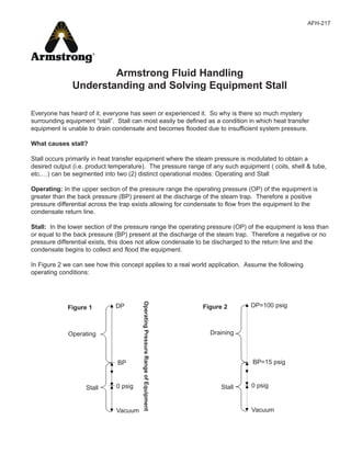
  • 1. Everyone has heard of it, everyone has seen or experienced it. So why is there so much mystery surrounding equipment “stall”. Stall can most easily be defined as a condition in which heat transfer equipment is unable to drain condensate and becomes flooded due to insufficient system pressure. What causes stall? Stall occurs primarily in heat transfer equipment where the steam pressure is modulated to obtain a desired output (i.e. product temperature). The pressure range of any such equipment ( coils, shell & tube, etc.…) can be segmented into two (2) distinct operational modes: Operating and Stall Operating: In the upper section of the pressure range the operating pressure (OP) of the equipment is greater than the back pressure (BP) present at the discharge of the steam trap. Therefore a positive pressure differential across the trap exists allowing for condensate to flow from the equipment to the condensate return line. Stall: In the lower section of the pressure range the operating pressure (OP) of the equipment is less than or equal to the back pressure (BP) present at the discharge of the steam trap. Therefore a negative or no pressure differential exists, this does not allow condensate to be discharged to the return line and the condensate begins to collect and flood the equipment. In Figure 2 we can see how this concept applies to a real world application. Assume the following operating conditions: DP Operating Stall BP 0 psig Vacuum Figure 1 OperatingPressureRangeofEquipment DP=100 psig Draining Stall BP=15 psig 0 psig Vacuum Figure 2 Armstrong Fluid Handling Understanding and Solving Equipment Stall AFH-217
  • 2. 2 It is clear that any time the air heating coil in Figure 3 modulates below 15 psig the system will fall into a “stall” condition. This condition is most likely to occur when there is a light heating load, causing the coil to operate at a fraction of its capacity and a fraction of the design pressure Effects of “stall” In a stall condition condensate accumulates within the equipment. When equipment becomes flooded by stalled condensate a variety of problems ranging from minor to catastrophic failure will occur. Problems associated with stall: n Inadequate condensate drainage n Waterhammer (Thermal shock) n Frozen coils n Corrosion due to cool condensate and the formation of Carbonic acid n Poor temperature control n Short equipment life n Control valve hunting (system cycling) n Reduction in heat transfer capacity Factors contributing to “stall” Stall happens for a variety of reasons, but it always comes back the fact that there is not always enough system pressure to return the condensate. The lack of sufficient pressure in the equipment may be caused by anyone of the following: n Oversized equipment (excessive surface area) n Overly conservative fouling factors n Back pressure at equipment discharge due to elevation or pressure in the line n Modulating control n Equipment operating at lower pressures due to light load demands n Vacuum Table 1 Design Pressure (DP) = 100 psig Back Pressure (BP) = 15 psig Incoming Air Temperature (T1) = -10°F Exit Air Temperature (T2) = 70°F Design Condensate Load (DL) = 3,000 lb/hr Figure 3
  • 3. 3 Many types of heat transfer equipment are susceptible to stall because they are designed with excessive safety factors built into the design. In attempting to provide an extremely robust heat exchanger, equipment manufactures and engineers often “over design” equipment which often lends itself to a stall scenario. Solutions? The problems of equipment stall are well known and well documented. Over the years there has been a variety of so called “solutions” that would all alleviate the stall scenario. Installation of a vacuum breaker: Objective: To relieve a vacuum within equipment allowing for condensate drainage. Shortcoming: 1. This practice will only help if the condensate is gravity drain to atmosphere, any pressure present at the discharge of the trap will not allow condensate drainage. 2. Allows undesirable air into the system. 3. Vacuum breakers often fail due to a poorly chosen location downstream of the equipment causing a build-up of scale/sediment impeding the operation. Such a location may also allow the hydrostatic pressure of a vertical water column to keep the vacuum breaker closed in a small vacuum. 4. Loss of valuable flash steam Installation of a safety drain: Objective: The use of a second steam trap located above the primary trap which discharges condensate to drain when the system goes into a stall condition. Shortcoming: A significant amount of condensate/flash steam and valuable BTU’s are lost down the drain when the system is in stall. Stall load may as high as 90% or more of the design load, therefore 90% of the condensate coming from the equipment goes down the drain Installation of a positive pressure system: Objective: The use of air or other gas to maintain set pressure to ensure a positive pressure differential across the trap allowing for condensate drainage. Shortcomings: Injects a significant amount of undesirable air into the equipment. This large amount of air may cause multiple problems: 1. Air acts as an insulator thereby decreasing the heat transfer capacity of the equipment. 2. A heavy dependence on air vents to evacuate the air from the equipment. 3. Air vents may be open a significant amount of time allowing for loss of valuable BTU’s. The Solution The application of a “closed” system pump trap on your modulating steam equipment can provide the following benefits: n Continuous condensate drainage, even in a vacuum n Eliminates the need for vacuum breakers n Saves valuable flash steam from escaping into the atmosphere
  • 4. 4 n No need to run expensive vent lines n Size pump traps on stall load, resulting in smaller pumps and less cost n No rotating seals, cavitation, or NPSH requirements n Negligible operating cost n Longer equipment life n Reduced corrosion n Better temperature control n Reduced maintenance…….and more The Closed Loop Concept The closed loop application of a pump trap is based around one basic concept: To equalize the pressure in the heat exchange equipment and the pump trap thereby allowing condensate to drain by gravity to the pump trap. The equalization of pressure is accomplished by: 1. Connecting the vent of the pump trap to the inlet steam side of the equipment or to a condensate receiver upstream of the pump trap. 2. Placing the steam trap on the outlet side of the pump trap or eliminating the steam trap altogether (if DP<BP) Figure 4 shows the appropriate piping configurations for a closed loop pump trap application. Connecting the vent line of the pump trap to the inlet steam side to the equipment is the preferred method of pressure equalization if the pressure drop across the heat exchange equipment is ½ psig or less. If the pressure drop is greater, the vent line of the pump trap should be connected to the condensate receiver upstream of the pump trap. The vent line must be connected into a vapor space, not into liquid. (Note: Piping from the equipment should be increased one pipe size and be pitched towards the receiver to avoid water seal) In either configuration the vent line should be increased one pipe size if the length is to exceed 6 feet. Figure 4
  • 5. 5 Equipment Sizing: The main components to be sized in a closed loop pump trap application are the pump trap and the steam trap (if necessary). Pump trap sizing: One major benefit of using a pump trap in a closed loop system is the ability to size the pump based on the stall load as opposed to the design load. This will almost always result in a smaller required pump capacity since the stall load is generally some fraction of the design load. The pump trap can be sized based on the stall load because: When the equipment operating pressure (OP) is above the back pressure (BP) the condensate is discharged into the return line by the positive pressure differential (draining mode). In this mode the pump trap is inactive, the condensate simply flows through the pump as if it were a piece of pipe. When the equipment operating pressure (OP) is less than or equal to the back pressure (BP), condensate is unable to be discharged into the return line due to insufficient pressure and the system goes into stall. Usually the condensate would accumulate in the equipment, but in a closed loop system the condensate collects in the pump trap. Once the pump trap is filled to the appropriate level the pump trap is activated and pumps the stalled condensate through the steam trap and into the return line. Hence the pump trap only pumps when the system is in “stall” and thereby allowing the pump trap to be sized based on the stall load as opposed to the design load. Sizing the steam trap in a closed loop system: The recommended steam trap for modulating service is generally a Float and Thermostatic (F&T) trap. The F&T trap is chosen for its continuous drainage, air venting capabilities, and the ability to handle the high instantaneous loads when used in conjunction with a pump trap in closed loop system. The steam trap in a closed loop system must be able to handle the demands of the heat exchange equipment and the instantaneous pumped loads of the pump trap. Therefore the steam trap must be sized twice, once for the equipment and once for the pump trap. Sizing the steam trap based on modulating heat exchange equipment. Sizing the steam trap based on the pump trap The larger trap from either method is the correct trap to be used in a closed loop system in conjunction with a pump trap. Determining Stall Load Operating parameters of the equipment and system can be graphed on a stall chart to determine two very critical points: 1. The minimum allowable flow rate before the equipment goes into a stall condition. The stall load is expressed as a percentage of the design load (assuming T1 is constant). 2. The maximum incoming temperature (T1) before the equipment goes into a stall condition (assuming flow rate is constant). Table 2 Operating Pressure Safety Factor 0 - 15 psig 2:1 @ 1/2 psi differential 16 - 30 psig 2:1 @ 2 psi differential > 30 psig 3:1 @ 1/2 max. pressure differential Table 3 Operating Pressure Safety Factor Must handle maximum pressure of heat exchange equipment Stall load @ 1/4 psi differential
  • 6. 6 To use the stall chart the following information must is required: n Design Pressure (DP) n Back Pressure (BP) n Incoming Temperature (T1) n Exiting Temperature (T2) Using the parameters from Table 1, the stall chart is plotted using the following steps: 1. Plot T1 = -10°F on the vertical axis on the left, then plot T2 = 70°F on the vertical axis on the right and draw a line to connect the points. 2. Determine the Mean Temperature (MT)= (T1+T2)/2 = (-10+70)/2 = 30°F. Plot MT=30°F on the vertical axis on the right. Plot the Design Pressure (DP) =100 psig on the vertical axis on the left. Draw a line to connect points MT and DP. 3. Plot the Back Pressure (BP) = 15 psig on the vertical axis on the left. Draw a horizontal line at BP across the chart. 4. At the intersection of line BP and line MT/DP drop a vertical line to determine that the stall load percentage (SL) = 73% 5. At the intersection line T1/T2 and vertical line SL, draw a horizontal line to the left to determine that the stall temperature (ST) = 13°F
  • 8. 8 With the information from the stall chart to critical points can be identified: 1. The Stall Load percentage (SL) indicates the coil is in a stall condition anytime the load drops below 73% of the Design Load (DL). Therefore the maximum amount of condensate being produced when the coil is in stall is SL x DL = .73 x 3000 lb/hr = 2190 lb/hr. In a closed loop system the pump trap can be sized on the stall load of 2190 lb/hr instead of the design load of 3000 lb/hr, resulting in a smaller, less expensive pump trap. 2. The Stall Temperature (ST) = 13°F indicates the coil is in a stall condition anytime T1 is greater than 13°F. Anytime incoming air is warmer than 13°F the coil will not drain condensate with out assistance. How many days a year is the outside temperature greater than 13°F, almost everyday!! Knowing the stall load, the pump trap and steam trap for our example in Figure 1 can be determined. Pump trap sizing example: *Assuming 12” fill head and 50 psig steam motive In an open system the pump trap would be sized for the design load of 3000 lb/hr resulting in the use of a larger PT-206 pump trap. Steam trap sizing example: Based on Pump trap Based on heat exchange equipment Both methods selected a 125-J8 steam trap, however if there were a difference the larger trap would be chosen. Conclusion Applications for applying pump traps in closed systems to eliminate problems with stall exist at almost every facility. The benefits of using a pump trap in a closed system to solve the problem of “stall” can provide multiple benefits that reduce maintenance, improve performance, increase equipment life, and provide significant cost savings in installation and operation. Table 4 Required Load Motive Pressure Available Back Pressure Pump Trap Model 2,190 lb/hr 100 psig steam 15 psig PT-204* Table 5 Stall Load Safety Factor Steam Trap Model 2,190 lb/hr Stall load @ 1/4 psi differential 2,190 @ 1/4 psi differential F&T 125-J8 Stall Load Safety Factor Steam Trap Model 3,000 lb/hr 3:1 @ 1/2 max. differential 9,000 @ 50 psi differential F&T 125-J8
  • 9. 9 Figure 6 Armstrong Fluid Handling, Inc., 221 Armstrong Blvd., P.O. Box 408, Three Rivers, Michigan 49093 - USA Ph: (616) 279-3601 Fax: (616) 279-3150 www.armstrong-intl.comAFH- 217 6/00 Printed in U.S.A.