Surge Protective Device -Meba
•
2 j'aime•1,153 vues

Surge Arrestor/SPD DC surge protective devices for PV system

Recommandé
Recommandé
Contenu connexe
Tendances
Tendances (20)
Similaire à Surge Protective Device -Meba
Similaire à Surge Protective Device -Meba (20)
Plus de Meba Electric Co.,Ltd
Plus de Meba Electric Co.,Ltd (20)
Dernier
Dernier (19)
Surge Protective Device -Meba
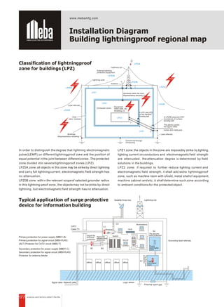
- 1. 177 Installation Diagram Building lightningproof regional map Classification of lightningproof zone for buildings (LPZ) Primary protection for power supply (MBD1-B) Primary protection for signal circuit (MBX-RJ45) (ALT) Protector for CATV circuit (MBD-T) Secondary protection for power supply (MBD1-C) Secondary protection for signal circuit (MBX-RJ45) Protector for antenna feeder In order to distinguish the degree that lightning electromagnetic pulse(LEMP) on different lightningproof zone and the position of equal potential inthe joint between differentzones. The protected zone divided into several lightningproof zones (LPZ). LPZ0A zone:all objects in this zone may be strikeby direct lightning and carry full lightning current, electromagnetic field strength has no attenuation. LPZ0B zone: withi n the relevant scopeof selected grounder radius in this lightning-proof zone, the objects may not be strike by direct lightning, but electromagnetic field strength has no attenuation. LPZ1 zone: the objects in thiszone are impossibly strike by lighting, lighting current on conductors and electromagnetic field strength are attenuated, the attenuation degree is determined by field solutions in the buildings. LPZ2 zone: if required to further reduce lighting current and electromagnetic field strength, it shall add extra lightningproof zone, such as machine room with shield, metal shellof equipment, machine cabinet and etc; it shall determine suchzone according to ambient conditions for the protected object. Typical application of surge protective device for information building LPZ0A LEMP LPZ0A LEMP LEMP LEMP LEMP LPZ0A LPZ0B LPZ0B LPZ1 LPZ2 LPZ3 LPZ1 LPZ0A LPZ0B 1 3 2 Lightning rod External lightning protection equipment Antenna Lead referrals (Computer room) Equipment metal case, etc Shielding (3) Structures within the room (Representative shie lding 2) Buildings (Representative shielding 1) In LPZ1 and LPZ2 on the interface bonding belt Lightning zone In LPZ0B area and LPZ1 boundaries of surface bonding belt Lead referrals The electric power, the signal cable, routes and metal pipe Ground net.through introducing (door, window) Hole CATV B1 B2 C2 C1 HUb A2 A1 Satellite three line Lightning rod Grounding lead referrals Cable TV Signal cable Network cable office office office office office Receiver Server Workstations Signal the first level protection Potential spark gap Total switchgear room Points switchgear room SwitchSignal the second level protection Thefirstlevel protection The second level protection Logic where
- 2. 178 N L3 L2 L1 PE MBD1-B100 MBD1-B80 MBD1-B65 MBD1-B60/3+NPE MBD1-C40/3+NPE L=5-10m L=5-10m MBD1-D10/1+NPE MBD1-D20/1+NPE Up 3.0kV Up 2.0kV Up 1.5kV TT System (1) Total distribution ark Distribution electricity ark Equipment place According to different protection modes, nomenclature and definitions of IEC standard, Low voltage distribution system divided into three kinds on basis of earthing mode of low voltage distribution system. 1. TT power supply network: TT mode is namely the protection system that metal shell of electric consumer directly earthed, calling protective earthing system, or TT system. 2. TN power supply network: this system require metal shell of electric equipment is connected with neutral line, also calling Neutral protection system, indicated by TN. 3. TN-C power supply network: neutral line also used as protective ea rthing wire, calling Neutral Protective earthi ng line, indicated by NPE. 4. TN-S power supply network: neutral line (N) and protective earthing (PE) wire are separated. 5. TN-C-S power supply network: in the temporary power supply for the constructing sit e, if front supply ne twork is TN-C, and TN-S network shall be required on local constructing sites, so PE line can be divided from general distribution box on local site. 6. IT network, I means isolation without earthing, or earthing via high resistance. Every two letters of 'T' means electric consumer of loading side is protective earthed. MBD Surge Protective Device(SPD) Installation diagram Basic network of Power Supply
- 3. N L3 L2 L1 PE MBD1-B60 MBD1-B40 L=5-10m L=5-10m MBD1-D10 MBD1-D20 Up 3.0kV Up 2.0kV Up 1.5kV MBD1-B100 MBD1-B80 MBD1-B65 Total distribution ark Distribution electricity ark Equipment place TT System (2) N L3 L2 L1 PE MBD1-B100 MBD1-B80 MBD1-B65 MBD1-B60 MBD1-C40 L=5-10m L=5-10m MBD1-D10 MBD1-D20 Up 3.0kV Up 2.0kV Up 1.5kV TN-S System PE Total distribution ark Distribution electricity ark Equipment place Installation Diagram Basic network of Power Supply 179
- 4. N L3 L2 L1 PE L=5-10m L=5-10m PE MBD1-B100 MBD1-B80 MBD1-B65 MBD1-B60 MBD1-C40 MBD1-D10 MBD1-D20 Up 3.0kV Up 2.0kV Up 1.5kV Total distribution ark Distribution electricity ark Equipment place L3 L2 L1 PE MBD1-B100 MBD1-B80 MBD1-B65 MBD1-B60 MBD1-C40 L=5-10m L=5-10m Up 2.0kV Up 1.8kV Total distribution ark Distribution electricity ark IT System The Wiring Diagram TN-C-S System Installation Diagram Basic network of Power Supply 180
- 5. MBD1-B100/80 Operation Elements Technical Parameter 108 L L L N 90 45 50 62 35 MBD1-B100 Rec Uc Imax In Up : : : : ~385V 100kA 60kA 3.0kV GB18802.1 IEC61643-1 MBD1-B100 Rec Uc Imax In Up : : : : ~385V 100kA 60kA 3.0kV GB18802.1 IEC61643-1 MBD1-B100 Rec Uc Imax In Up : : : : ~385V 100kA 60kA 3.0kV GB18802.1 IEC61643-1 MBD1-B100 Rec Uc Imax In Up : : : : ~385V 100kA 60kA 3.0kV GB18802.1 IEC61643-1 Installation To be mounted between LPZ0Aor LPZ0B zone and LPZ1 zone, adopts 35mm standard mountin g rail. The cross sectional area of 2 multi-strand soft copper conductor: 6~ 35mm . Generally it shall be mountedin the incoming side of main distribution panel or box. 2 Earthing wire shall be of 10mm dual color conductor, its lengthnotmorethan500mm. In order toeliminate the influence on normal service of power netwo rk due SPD is invalid, it shall add fuse or breaker to be series connected in Lline. (NB: selected according to standard current In) SPD as only one side of terminals, able to prevent from being electric touching, indoor fixedly mounted, limiting voltage. SPD has built-in disconnector, when SPD is invaliddue to overheating or breakdown, the disconnector can automatically separate SPD from the network, meanwhile send an indication signal. The visible window show white color in normal service, if to be separated from network, it will show red color. Maxi discharging current of each wire: up to 100KA. Model and specification MBD1-B60 MBD1-B80 MBD1-B100 Maxi discharging current Nominal discharging current Response time Application Protection grade Remote signal Function Indication of invalidation Remarks 60 80 100 <25 IP20 Primary protection for in line Can also picking Maxi continuous operating voltage Voltage protective level 750 3.5 420 2.2 385 2.0 275 1.6 420 2.5 385 2.3 320 2.0 275 1.8 420 3.0 385 3.0 320 2.5 275 2 30 40 60 Aging invalidation: white: Normal, red: invalidation Other maxi continuous operating voltage Canbe customized MBD1 Series Surge Protective Device Product introduction MBD1 series surge protective device (herei nafte r called SPD) is suitably used in the IT, TT, TN-C, TN-S,TN-C-S and etc power supplysystem ofAC 50/60Hz, rated voltage up to 380V, to protect from direct and indirect lightning impulse and other transient over voltage.As perthe conditions of IEC61643-1:1998-02 standard, Class I surge protective device, it is category B surge protective device. SPD has two protection modes: MC and MD, SPD is in compliance with GB18802.1/IEC61643-1 standards. Model and Signification MB D 1 100 385- - - Number of poles: 1P 2P 3P 4P Maxi continuous operating voltage Uc(V) Maxi discharging current Imax(8/20 s)(kA) Design No Surge Protective Device(SPD) Enterprise code - Remote signal B, C, D level protection Outside Size Fig 181
- 6. MBD1-B60 Installation The SPD need not to be adjusted afte r in-stalled according to requirement. It can automatically protect the power net-work after proper installation. On services it need periodically check if SPD isinvalid ornot,meanwhile checkred indicator of fuse lightingor not, please rep- lace the invalid element on time. Operation Elements Technical Parameter MBD1-B Series Surge Protective Device Product introduction MBD1-B series surge protective device (hereinafter called SPD) is suitably used in the IT, TT,TN-C, TN-S, TN-C-S and etc power supply system ofAC 50/60Hz, rated voltage up to 380V, to pr otect from direct and indirect lightning impulse and other transient overvoltage. As per theconditions of IEC61643-1:1998-02 standard, ClassI surge prote -cti ve device, it is category B surge protective device. SPD has two protectionmodes: MC andMD SPD is in compliance with GB18802.1/ IEC61643-1 standards. In three phases and four wires system, all three phaselines and oneneutral line to earthing line haveSPD to be protected, in normal service,the SPD isat the state of high resistance,when networkproduce surging over-voltage dueto thunder or other reasons, SPD will be conductive within short time (ns), lead surging voltage into ground, consequentlyto protect theelectric appliances ofnetwork. Aftersurging voltage passed by SPD, and disappeared, SPD recover in high resistance. It will nothave influence on thenormal service ofnetwork. Outside Size Fig 91 45 L NL L 72 50 62 35 MBD1-B60 Rec Uc: Imax: In: Up: ~385V 60kA 30kA 2.0kV GB18802.1 IEC61643-1 MBD1-B60 Rec Uc: Imax: In: Up: ~385V 60kA 30kA 2.0kV GB18802.1 IEC61643-1 MBD1-B60 Rec Uc: Imax: In: Up: ~385V 60kA 30kA 2.0kV GB18802.1 IEC61643-1 Rec MBD1-B60 Uc: Imax: In: Up: ~385V 60kA 30kA 2.0kV GB18802.1 IEC61643-1 Model and specification MBD1-B60 MBD1-B80 Maxi discharging current Nominal discharging current Response time Application Protection grade Remote signal Function Indication of invalidation Remarks 60 80 <25 IP20 Primary protection for in line Can also picking Maxi continuous operating voltage Voltage protective level 30 40 Aging invalidation: white: Normal, red: invalidation Other maxi continuous operating voltage Canbe customized 420 2.2 385 2.0 320 1.8 275 1.6 420 2.5 385 2.3 320 2.0 275 1.8 A B C N L L L N 1 2 1 2 1 2 Principle Diagrams Figure 1 380 V network diagram Figure 2 surge protector electrical diagram Note: 1 heat failure from the 2 pressure sensitive resistors 182
- 7. MBD1-C40 Installation To be mountedbetween LPZ0B or LPZ1 zone and LPZ2 zone, adopts 35mm standard mounting rail. The cross sectional area of multi-strand soft copper conductor: 2.5~35 2 mm . Every phase of SPD shall be protected by fuse or mini circuit breaker fromshort circuit when SPD is broken downcaused by surging voltage. It is mounted in distribution boxesof different floors, computer center, telecommunication room, control room of elevator, CATV room, fire fighting center, distribution box of villa and etc. A B C N L L L N 1 2 1 2 1 2 Principle Diagrams Figure 1 380 V network diagram Figure 2 surge protector electrical diagram Note: 1 heat failure from the 2 pressure sensitive resistors 91 45 L NL L 72 50 62 35 MBD1-C40 Rec Uc: Imax: In: Up: ~385V 40kA 20kA 1.8kV GB18802.1 IEC61643-1 MBD1-C40 Rec Uc: Imax: In: Up: ~385V 40kA 20kA 1.8kV GB18802.1 IEC61643-1 MBD1-C40 Rec Uc: Imax: In: Up: ~385V 40kA 20kA 1.8kV GB18802.1 IEC61643-1 MBD1-C40 Rec Uc: Imax: In: Up: ~385V 40kA 20kA 1.8kV GB18802.1 IEC61643-1 MBD1-C Series Surge Protective Device Product introduction Outside Size Fig MBD1-C series surge protective device (hereinafter called SPD) is suitably used in the IT, TT, TN-C, TN-S, TN-C-Sand etc power supplysystem of AC 50/60Hz,rated voltage up to 380V, to protect from dir ect and indirect lightning impulse and other transient over voltage. Asper the conditions of IEC61643-1: 1998-02standard, ClassII surge prote-ctive device, it is category C surge protective device. SPD has two protection modes: MCandMD SPD is in compliance with GB18802.1/ IEC61643-1 standards. Operation Elements SPD as onlyone side ofterminals, able to prevent from being electric touch ing, indoor fixedly mounted, limiting voltage. SPD has built-in disconnector,when SPD is invaliddue to overheatingor breakdown, the disconnector canautomatically separate SPDfrom the network,meanwhile send an indication signal. The visible window show white color in normal service, if to be sepa-rated from network, it will show red color. 1P+N, 2P+N, 3P+N SPD consist of 1P 2P 3P SPD and NPE neutral and earthing protection modules, used in the power supply system of TN-S, TN-C-S and etc. Technical Parameter Other maxi continuous operating voltage Canbe customized Can also picking Secondary protection for in line 20 750 3.0 420 2.0 385 1.8 320 1.6 275 1.5 175 1.3 48 0.6 <25 IP20 40 Aging invalidation: white: Normal, red: invalidation MBD1-C40 Remarks Remote signal Function Application Indication of invalidation Protection grade Model and specification Maxi discharging current Nominal discharging current Response time Voltage protective level Maxi continuous operating voltage 183
- 8. MBD1-D20 Principle Diagrams L/N M1 V t V: high-energy MOV Ft: Large current fusing t : Hot open circuit device M I: Open circuit instructions device Red failure, White normal MBD1-D Series Surge Protective Device Outside Size Fig Product introduction MBD1-D series surge protective device (hereinafter called SPD) is suitably used in the IT,TT,TN-C, TN-S, TN-C-S and etc power supply system of AC50/60Hz, rated voltage up to 380V, to protect from direct and indirect lightning impulse and other transient over voltage. Asperthe conditions of IEC61643-1:1998-02 standard, Class III surge protective device, it is category D surge protective device. SPD hastwo protection modes: MC and MD SPD is in compliance with GB18802.1/ IEC61643-1 standards Installation To be mountedbetween LPZ1 orLPZ2 zone and LPZ3 zone, adopts 35mm standard mounting rail. The cross sectional area of multi-strand soft copper conductor: 2.5~ 35 2 mm . Every pole of MBDshall be protected by fuse or mini circuit breaker. It is mounted in distribution boxes of living house, computer center, communication equipment, electronic equipment and control equipment or nearest socket box. 91 45 L NL L 72 50 62 35 MBD1-D20 Rec Uc: Imax: In: Up: ~385V 20kA 10kA 1.5kV GB18802.1 IEC61643-1 MBD1-D20 Rec Uc: Imax: In: Up: ~385V 20kA 10kA 1.5kV GB18802.1 IEC61643-1 MBD1-D20 Rec Uc: Imax: In: Up: ~385V 20kA 10kA 1.5kV GB18802.1 IEC61643-1 MBD1-D20 Rec Uc: Imax: In: Up: ~385V 20kA 10kA 1.5kV GB18802.1 IEC61643-1 Operation Elements SPD as only one side of terminals, able to prevent from being electrictouching, indoor fixedly mounted, limiting voltage. SPD has built-indisconnector, when SPD isinvalid due to overheating or breakdown, the disconnector can automatically separate SPD from the network, meanwhile send an indicatio n signa l. The visi ble window show white color in normal service, if to be sepa-rated from network, it will show red color. 1P+N, 2P +N, 3P+N SPD consist of 1P 2P 3P SPD and NPE neutral and earthing protection modules, used in the powersupply system of TN-S , TN-C-S and et c. Technical Parameter Model and specification Other maxi continuous operating voltage Canbe customized Can also picking Several protection for in line Aging invalidation: white: Normal, red: invalidation IP20 <25 Remarks Remote signal Function Application Indication of invalidation Protection grade Response time Nominal discharging current Maxi discharging current Voltage protective level Maxi continuous operating voltage 420 1.8 385 1.5 320 1.4 275 1.2 420 1.6 385 1.3 320 1.2 275 1.0 750 2.5 750 2.0 20 10 10 5 MBD1-D20 MBD1-D10 184
- 9. MBD1-RC40 MBD1-R Series Fuse Combination Surge Protective Device MB D 1- R / / / Enterprise code Surge Protective Device(SPD) Design No Maxi discharging current Imax(8/20 s)(kA) Maxi continuous operating voltage Uc(V) Remote signal Fuse Combination Number of poles: 1P, 2P, 3P, 4P 1P+NPE, 3P+NPE Features Technical Parameter Product introduction Model and Signification In order to meet with user demand, we developed new generation MBD1-R series protector with built- in circuit breaking devi ce, to limit surge current,overvoltage, over-current occurred in thepower system due to somereasons, working in the system of AC50Hz, rated voltage380V and bel ow to prevent surge voltage from damaging electric equipment. MBD1-R series protector has integrated short circuit protective function in its SPD module, fuse notneeded again, itcan be mountedon35mm railway, compared with normal combination of fuse+ SPD module, there has following advantages: Residual voltage reduce morethan 50%, for normal combination, fuse bodyandconnected conductor haveinductance,and willresult in residual voltage, but MBD1-R series almos t has noresidualvoltage at this case, therefore it can getbetter result ofprotecting equipment. Easy installation, saving space, saving installation cost in cabinet. Quicker response speed,comprehensive performance being improved. Better N point:no matter which step of circuit, there has shortestdistance for discharging surge current,residualvoltage decrease more. Model and specification MBD1-RB60MBD1-RC40MBD1-RD20MBD1-RD10 AC220V/AC380V AC385V/AC420V 30 60 40 20 20 10 10 5 1.8/2.01.5/1.81.2/1.51.0/1.2 1P 2P 3P 4P 1P+NPE 3P+NPE 25ns Ip20 Rated working voltage Un(AC) Maxin continuous operating voltage Nominal discharging current In Max discharging current Imax Protective level Up (kV) Pole combination Response time tA Outline size mm (Lx H x W) Protective grade Indication of invalidation Remote signaling function Able to provide if required. Aging invalidation: white: Normal, red: invalidation Short circuit invalidation: red LED shining. 135*73*18n Pole number MBD1-RB80 40 80 2.0/2.5 Remark Other maxi continuous working voltage Uc(AC) 175V 275V 320V, can be supplied if required. 185
- 10. MBD1-D20-N-PE 91 45 L N L L 72 50 62 35 MBD1-D20 Rec Uc: Imax: In: Up: ~385V 20kA 10kA 1.5kV GB18802.1 IEC61643-1 MBD1-D20 Rec Uc: Imax: In: Up: ~385V 20kA 10kA 1.5kV GB18802.1 IEC61643-1 MBD1-D20 Rec Uc: Imax: In: Up: ~385V 20kA 10kA 1.5kV GB18802.1 IEC61643-1 N-PE Uc: Imax: Up: ~255V 40kA(8/20) 1.1kV GB18802.1 IEC61643-1 Technical Parameter N-PE Series Surge Protective Device Product introduction Outside Size Fig L1 L2 L3 N PE L N PE Figure 1 Figure 2 Principle Diagrams N-PE surge protective device module (here inaft er called SPD) is suitable for the "3+1" circuitprotected modeTTsystem of AC 50/60Hz, rated voltage up to 380V, used in bet ween equal potential system of neutral and PE line, to protect from direct and indirect lightningimpulse and other transient over voltage. If cooperated with MBD1-C40 series surge protec tive device, it is constructed as 1P+1NPE; 2P+NPE, 3P+NPE combined SPD, this is to improve the surging protective performance. As per the conditions of IEC61643-1:1998-02 standard, Class II surgeprotective device, it is category C surge protective device. N-PE meets withGB18802.1/IEC61643-1 standards. Operation Elements The main operating element of NPE is gas discharging tube or air discharging gap, ge- nerally, it is high resistance between electr- odes, while the surge of direct and indirect lightning impulse and other transient over voltage influence on the power network, the SPD between electrodes will be conductive within short time (ns), and leading surging current into ground, consequently to protect the electric appliances of network. After surging voltage passed by NPE, and disa- ppeared, NPE recovers in high resistance. It will not have influence on the normal service of network. Installation NPE and MBD1-C series surge protective devices forms MBD1-40-1P+N, 2PN, 3+P+N and etcSPD, with MC and MD protection modes. NPE adopt s 35mm standard mounting rail. 2 Neutral line is of 2.5~ 35 mm conductor, eart hing wire shall be dual color multi- 2 strand copper conductor of morethan 4mm , the length not more than 500mm. Maxi continuous operating voltage Model and specification Voltage protective level Remarks Remote signal Function Application Protection grade Response time Maxi discharging current Nominal discharging current Indication of invalidation Other maxi continuous operating voltage Canbe customized Can also picking Aging invalidation: white: Normal, red: invalidation Several protection for in line IP20 25 20 40 MBD1-NPE L-N N-PE L-N N-PE 420 2.0 385 1.8 320 1.6 275 1.5 1.2 255 186
- 11. MBD1A-C With sound and light alarm module appearance and size (mm) Technical Parameter Model and specification Maxi carrying capacity Nomial carrying capacity MBD1S-B MBD1S-C MBD1S-D 80 40 60 30 40 20 20 10 10 5 Technical Parameter Model and specification Maxi carrying capacity Nomial carrying capacity MBD1A-B MBD1A-C MBD1A-D 80 40 60 30 40 20 20 10 10 5 MBD1S-C series remote sign- aling surge protective device MBD1S/A-C Series Remote Signaling/Acoustic-optical Alarm Surge Protective Device Product introduction Model and Signification The acoustic-optical alarm module shall operate with module surge protective device, used in AC 50/60Hz, 220V/385V power supply system,the protectiongrade and number of poles (1P 2P 3P 4P) are determined by user. Once power source module isout of oper- ation, acoustic alarm sounds, red LED flash, meanwhile it will give a command signal to a terminal for alarm against in va li di ty, which has NO, NC contacts, namely NC marked with 1, 2, NO marked with 1, 3; whilealarming, push black button to cancel the alarm soundtemporarily, red LED continue flashing, if fault module is not replaced, the acoustic alarm will sound again, after to replace the fault module, red LED go out,SPD return tonormal operation. Disconnector built in SPD, when SPD is inva lid due to breakdown come from over heating, over-current, the disconnector will cut off the SPD automatically and give indication signal of changed color. When SPD work normally, the visible window of module will show green, once invalid, it will show red, and produce acousticoptical alarm via connecting rod on the base, indi- cating the status of SPD is innormal service, aging, tripped temperature fuse or over- current and etc. Enterprise code Surge Protective Device(SPD) S: Output of remote signal A: Output of acoustic-optical alarm MB D 1 A/S - B/C Protected Category Design No MBD1A-C series acoustic-optical alarm surge protective device Disconnector built in SPD, when SPD is in-valid due to breakdown come from over- heatin g, over-current, the disconnector will cut of f the SPD automatically and give indication signal of c hanged color. When SPD work normally, the visible window of modul e will show g reen, o nce in vali d, it wi ll show r ed, and produce acousticoptical alarm via con- necting rod on the base,indicatingthe status of SPD i s in no rmal se rvice, aging, tripped temperature fuse or over-current and etc. 2 3 2 3 1 1 L L L NL N 90 18 62 5018 90 45 35 Buzzer Power Reset 24 Hour LED Arrester 1 2 3 MBD1-C40 Rec Uc: Imax: In: Up: ~385V 40kA 20kA 1.8kV GB18802.1 IEC61643-1 MBD1-C40 Rec Uc: Imax: In: Up: ~385V 40kA 20kA 1.8kV GB18802.1 IEC61643-1 MBD1-C40 Rec Uc: Imax: In: Up: ~385V 40kA 20kA 1.8kV GB18802.1 IEC61643-1 MBD1-C40 Rec Uc: Imax: In: Up: ~385V 40kA 20kA 1.8kV GB18802.1 IEC61643-1 Normal Failure 187
- 12. MBD2-40 Operation Elements SPD has built-in disconnector, when SPD is invalid due to overheating or breakdown, the disconnector can automaticallyseparate SPD from the network, meanwhile send an indication signal. The visible window show white color in normal service, if to be sepa- rated from network, it will show red color. Installation To be mounted between LPZOB or LPZ1 zone and LPZ2 zone, adopts 35mm st andard mounting rai l. The cross sectional area of multi -strand sof t copper conductor: 2.5~ 2 35 mm . Every pole of SPD shall be protected by fuse or mini circuit breaker. As required,the user can assemble single poleor three poles surge protective device freely. MB D 2 65 385- - - Number of poles: 1P, 2P, 3P, 4P Maxi continuous operating voltage Uc(V) Maxi discharging current Imax(8/20 s)(kA) Design No Surge Protective Device(SPD) Enterprise code Outside Size Fig 65 50 45 35 N L1 L2 L3 72 18 91 57 45 C40 Red: Replace Imax: In: Up: Uc: 40kA 20kA 1.5kV 340V~ MBD2 GB18802.1 C40 Red: Replace Imax: In: Up: Uc: 40kA 20kA 1.5kV 340V~ MBD2 GB18802.1 C40 Red: Replace Imax: In: Up: Uc: 40kA 20kA 1.5kV 340V~ MBD2 GB18802.1 C40 Red: Replace MBD2 GB18802.1 MBD2 Series Surge Protective Device Product introduction Model and Signification MBD2 series surge protector (hereinafter referred to as the SPD) is in absorbing foreign advanced technology research and development on thebasis ofnew replaceable type SPD. SPD is suitable for use in ac 50/60 Hz ac rated voltage 380 V, belowthe power supply system of indirect or direct lightning, the lightning influence or other instantaneous overvoltage protection. SPD has common mode (MC)anddifferential mode (MD) protection way. SPD accord with GB18802.1 / IEC61643-1. Technical Parameter Can also picking Protection for in line Aging invalidation: white: Normal, red: invalidation Model and specification Response time Application Protection grade Remote signal Function Indication of invalidation IP20 <25 Nominal discharging current Maxi discharging current Voltage protective level 420 2.5 MBD2-65 275 2.0 65 30 40 15 15 5 8 2 275 0.8 420 1.2 275 1.0 420 1.5 275 1.2 420 2.0 MBD2-40 MBD2-15 MBD2-8 Maxi continuous operating voltage 188
- 13. MBD3-40/120 Operation Elements Technical Parameter MBD3 Series Surge Protective Device Product introduction Model and Signification MBD3- B series surge protective device (hereinaf ter called SPD) is suitably used in the IT, TT,TN-C, TN-S, TN-C-S and etc power supply system of AC 50/60Hz, rated voltage up to 380V, to protect from direct and indirect lightning impulse and other transient overvoltage.As per theconditions of IEC61643-1:1998-02 standard, Cla ss I surge protective device, it is category B surge protective device. SPD meets with GB18802.1/IEC61643-1 standards. Installation Category B surge protective device (SPD), used in the connection between equal pot- ential electrodes while thunder occur. To be mounted: between LPZ0A or LPZ0B zone and LPZ1 zone, adopts 35mm standard mounting rail. The cross sectional area of 2 multi-strand soft copper conductor: 2.5~35mm. Generally to be installed in low voltagemain incoming distribution panel, overhead incoming. As required, theuser can assemble single pole or three poles surge protective device freely. Generally to be installed in low voltage main incoming distribution panel, earthing wire shall be dual color multi-strand soft copper 2 conductor more than 16 mm MB D 3 120 385- - - Number of poles: 1P, 2P, 3P, 4P Maxi continuous operating voltage Uc(V) Maxi discharging current Imax(8/20 s)(kA) Design No Surge Protective Device(SPD) Enterprise code Single pole structure, single pole or three poles combined SPD available. SPD has built-in disconnector, when SPD is invalid due to overheatingor breakdown, the disconnector can automatically separate SPD from the network, meanwhilesendan indication signal. The visiblewindow show white colorinnormal service, if to be separated fromnetwork, it will show red color. It can adopt Kelvin wiring mode. Large current carrying capacity, fast response time, low residual voltage. Model and specification Voltage protective level <25 IP20 Maxi discharging current Nominal discharging current Response time Application Protection grade Indication of invalidation 420 2.5 275 1.8 420 2.8 275 2.0 420 3.0 275 2.0 Protection for in line Aging invalidation: white: Normal, red: invalidation 420 2.5 275 1.5 420 1.8 275 1.5 80 100 120654515 40 50 6030155 MBD3-80 MBD3-100 MBD3-120MBD3-65MBD3-40MBD3-15 420 1.2 275 1.0 Maxi continuous operating voltage 69 46 35 36 87 57 45 Uc: 385V Imax:120kA(8/20) In: 60kA(8/20) Up : 3.0kV Ref.8144-03-03 Rec Rec Imax:40kA Uc: 420V In : 15kA UP:1.8kV MBD3-40 18 87 58 45 MBD3-40 Outside Size Fig 189
- 14. MBD4-40 Installation L L L N 72 100 90 45 66 51 35 MBD4-C Uc : In : Imax: Up : ~385V 20kA 40kA 1.8kV Surge Protective Device MBD4-C Uc : In : Imax: Up : ~385V 20kA 40kA 1.8kV Surge Protective Device MBD4-C Uc : In : Imax: Up : ~385V 20kA 40kA 1.8kV Surge Protective Device MBD4-C Uc : In : Imax: Up : ~385V 20kA 40kA 1.8kV Surge Protective Device Outside Size Fig Product introduction Model and Signification MBD4 series surge protective device (hereinafter called SPD) is sui-tably used in the IT, TT, TN-C, TN-S, TN-C-S and etc power supply system of AC50/60Hz, rated voltage up to 380V, to protect from direct and indirect lightning impulse and other transient over voltage. SPD meets with GB18802.1/IEC61643-1 standard. MBD4 Series Surge Protective Device Operation Elements SPD as only one side of terminals, able to preventfrom being electric touching, indoor fixedly mounted, limiting voltage. SPD has built-in disconnector, when SPD is invalid due to overheating orbreakdown, the disconnector can automatically separate SPD from the network, meanwhile sendan indication signal. Thevisiblewindow show white colorin normal service, if to be sepa- rated from network, it will show red color. Fast response time, low residual voltage. To be mountedin joint of LPZ1 or LPZ2 zone, adopts 35mm standard mounting rail. The cross sectional area of multi-strand soft 2 copper conductor: 2.5~ 35 mm . Every pole of SPD shall be protected by fuse or mini circuit breaker. The Contact SPD can provide the NOcontact for remote communication, if one or more modules of SPD is invalid, the NO andNC contact will be closed and send fault information. MB D 4 40 385- - Maxi continuous operating voltage Uc(V) Maxi discharging current Imax(8/20 s)(kA) Design No Surge Protective Device(SPD) Enterprise code Technical Parameter Remarks Remote signal Function Application Indication of invalidation Protection grade Response time Nominal discharging current Maxi discharging current Voltage protective level Maxi continuous operating voltage Model and specification Other maxi continuous working voltage Uc (AC) can be supplied if required. <25 IP20 Protection for in line Can also picking Aging invalidation: white: Normal, red: invalidation 20 10 40 20 420 1.8 275 1.2 420 2.0 275 1.5 MBD4-20 MBD4-40 190
- 15. MBD5-120 Outside Size Fig MBD5 Series Surge Protective Device Model and SignificationProduct introduction MBD5 series surge protective device (hereinafter called SPD) is suit-ableforthe IT, TT, TN-C, TN-S, TN-C-S and etcpower supply system ofAC 50/60Hz, rated voltage 380V andbelow, to protect from lightning impulse and other transient over voltage, it is applica ble in class I lightning proof system where there has higher danger of lightning strikes As per the conditions of IEC61643-1:1998-02 standard, Class I surge protective device, it is category B surge protective device. SPD meets with GB18802.1/IEC61643-1 standards. Operation Elements Fast response time: less than 25ns Low limited voltage Large current carrying capacity Normal state: white color, invalid state: red color Kelvin wiring mode available. Installation Category B surge protective device(SPD), used in the connection between equal potential electrodes while thunder occur. Generally to be installed in low voltagemain incoming distribution panel, overhead incoming. To adopt 35mm standard mounting rail for SPD mounting. When to place an order, please indicate the model, specification and quantity of SPD. 2 It shall adopt 10~35mm copperconductor to be connected with SPD, earthing wire shall be dual color multi-strand soft copper 2 conductor more than 16mm . The Contact SPD can provide theNO contact for remote communication, if one or more modules of SPD isinvalid, the NO andNC contact will be closed and send fault information. MB D 5 120 385- - - Number of poles: 1P, 2P, 3P, 4P Maxi continuous operating voltage Uc(V) Maxi discharging current Imax(8/20 s)(kA) Design No Surge Protective Device(SPD) Enterprise code Surge Protective Device MBD5-120 Uc~: In(8/20): Imax(8/20): Up: 385V 60kA 120kA 2.5kV 36 90 RED:TO BE REPLACED L(N) 35 65 Technical Parameter <25 IP20 MBD5-100 50 Model and specification Response time Application Protection grade Remote signal Function Indication of invalidation Remarks Can also picking 420 2.5 385 2.3 275 1.8 420 2.5 385 2.3 MBD5-120 MBD5-150 320 2.0 275 1.8 420 3.5 385 3.2 320 2.5 275 2 60 100 120 150 80 Primary protection for in line Other maxi continuous operating voltage Can be customizedUc175,440,690V Nominal discharging current Maxi discharging current Voltage protective level Maxi continuous operat ing voltage Aging invalidation: white: Normal, red: invalidation 191
- 16. MBD6-40 MB D 6 40 385- - - Number of poles: 1P, 2P, 3P, 4P Maxi continuous operating voltage Uc(V) Maxi discharging current Imax(8/20 s)(kA) Design No Surge Protective Device(SPD) Enterprise code Accessories: X-the contact Installation MBD6-20 is mounted between LPZ1 or LPZ2 zone and LPZ3 zone. The cross sectional area ofmulti-strand soft copper 2 conductor to be connecte d: 2.5~ 35mm . It is used in distribution boxes of living house, computer center, communication equipment, electronic equipment and control equipment ornearest socket box. MBD6-40 is mounted between LPZ0Bor LPZ1 zone and LPZ2 zone. The cross sectional area of multi-strand soft copper 2 conductor to beconnected: 2.5~ 35mm . The Contact Contact for remote communication can be provided for SPD, thecontact has one pair for transferring, 11 as middle position, 12 and 11 opened under SPD acting, 14 and 11 closedunder SPD acting, 11 and 14 as NO contact . If one or more of modules of SPD is invalid, the contact will be closed and send fault signal. Outside Size Fig Technical Parameter Model and specification Voltage protective level Response time Protection grade Application Remote signal Function Indication of invalidation Remarks Other maxi continuous operating voltage Canbe customized Can also picking Protection for in line Aging invalidation: white: Normal, red: invalidation IP20 <25 60 30 40 20 20 10Nominal discharging current Maxi discharging current Maxi continuous operating voltage MBD6-60 420 2.5 385 2.0 MBD6-40 MBD6-20 320 1.8 275 1.6 420 2.0 385 1.8 320 1.6 275 1.3 420 1.8 385 1.5 320 1.3 275 1.2 MBD6 Series Surge Protective Device Model and SignificationProduct introduction MBD6 series surge protective device (hereinafter called SPD) is suitably used in the TT TN-S TN-C IT TN-C-S and etc power supply system of AC 50/60Hz, rated voltage 380V and below, to protect from direct and indirect lightning impulse and other transient over voltage. SPD meets with GB18802.1/IEC61643-1 standard. MBD6-C Uc : ~385V In : 20kA Imax: 40kA Up : 1.8kV N L L L 18 72 90 45 63 49 35 Surge Protective Device MBD6-C Uc : ~385V In : 20kA Imax: 40kA Up : 1.8kV Surge Protective Device MBD6-C Uc : ~385V In : 20kA Imax: 40kA Up : 1.8kV Surge Protective Device MBD6-C Uc : ~385V In : 20kA Imax: 40kA Up : 1.8kV Surge Protective Device 192
- 17. MBX-R/L24 MBX-R/L Series Surge Protective Device MBX-R/ L surge pr otect or prot ect un-earthed dat a (asymmetrica l, suspended) cable that used fordual wire electronicmeasurement and control and the voltage shall not exceed 110V, frequency not more than 2MHz, to preventdata cabl e and relate d equipment from being damaged due to surging over-voltage caused by lightning or traveling wave. It is mounted between LPZ1 LPZ3. MBX-R/L two-stage circuit consists of gas discharging tube, piezore-sistance and clamping diode, with advantages of large discharging capacity, short clamping time and low protection level. MBX-R/L protector can be mounted on 35mm rail of different sta ndard switching box or distribution box. It does not needscrews for connecting with terminal. Function and application 62 50 35 18 91 45 IN OUT 1 PE 2 4 PE 3 MBX-L24 : : : : : 24V 27V 200mA 5kA 80V UN Uc IL In(8/20) Up Technical ParameterOutside Size Fig MBX-R/L 1 3 5V 7V 13V 6V 9V 20V 12V 15V 30V 24V 30V 51V 48V 51V 100V 0.2A 1.0A Arrester 10KA Mounting position 100 H 15 Nominal voltage Max. continuous operating voltage Voltage protective level Rated loading current of category R Rated loading current of category L Nominal discharging current Series connected resistance of each line of category R Series connected inductance of each line of category L Cross sectional area of connected conductor Peel-off length for the wireto be connected Color 2 0.14-2.5mm 6-7mm Grey Material Fire resistant reinforced PC Applicable standard GB18802.2 IEC61643-21 193
- 18. MBX-N MBX-N Series Surge Protective Device Product introduction Model Signification MB X - N / SPD used in signal control line of data transmission. Network Surge Protector Enterprise code Protection Port 8 16 24 Technical Parameter MBX-N 12V 5KA(8/20) <35V <0.2VdB 10ns RJ45 Model and specification Rated voltage Protective level Insertion loss Response time Interface mode Flux Installation This surge protect ive device will be series connected between circuit and protected equipment, outp ut terminal of SPD shall be connected with input of equipment to be protected,the circuit distanceconnected shall beshort as possible, this can get best protection effect. The PE line shall be reliably connected with earthing line of lightning system, this leading wire shall be shortest as possible, to get good protection effect. If this SPDdischarged the surgingmany times andtake on invalidation, please replace it on time, to ensure continuous safety. This product belong to termination protection device, due to uncertainty of lightning and surging, itshall cooperate well with anterior protectionappliance inconsideration of working conditions, in order to get good protection effect . Lightning injury mainly is by the way of the line of power supply orsignal circuits for connected equipment.Cons equen tly it is necessarythat it shallprotect power line or circuits effective ly from being damaged or personnel injury. MBX-N series surge protective device, adopts international latest gas discharging tube, TVS tub e, solid dischargingtube of quickerresponse, good non-linear curve, large flux, as the protective elements, assembled with auxiliary components, via optimized production technology. Which lessen the output residual voltage. When equipment happento over-volt age, this SPD quickly respond leading over- current discharged into ground, limiting the line voltage within permissible value, and finally to protect personnel safety and equipment from being damaged. The product meetswith IEC61643-1 and related standards. Product purpose Surging protection for computer, network station, data exchanging network can avoid the damage due to inductive voltage and surging voltage coming from signal circuit. 194
- 19. MBX-DB9/25MBX-Z Product introduction Product introduction Computer network lightning protector is mainly usedto prevent lightning (overvoltage) from access to equipment via network circuits, widely serving for the network equipments in banking system, communicationsystem, traf fic and transportation system, petrochemical control system and etc. Characteristics High surge current passing by; multi-step protected. Built-in fast semi-conductiveprotective element, quickresponse speed and lower residual voltage. Low inserting loss, ensure circuit working safely. Core element adopted international famous products, with excellent performances. It is to be easy installed, suitable for different standard ports. Operation instruction This product is of series connected mode. Please choosethe right protector withsameport of the equipment to be protected. In the protector, "IN" isinput terminal, "OUT"is output terminal, input terminal connected with exterior wires, output terminal connected to input side of the equipment to be protected. PE line ofprotector must beconnected solidl y to earthing wire of lightning proofsystem, connected wire shall be short, large and straight. During servicing, the protector shall beinspected periodically, if some fault happen, it shall be repaired or replace on time. Earthing resistance not larger than 4Ù. Laypeople do not remove. Monitoring Comprehensive Surge Protector MBX-Z Series Model Signification 220 2MB X - Z / SPD used in signal control line of data transmission. Enterprise code Two in One, Three in One Power supply voltage Monitoring comprehensive surge protector MBX-Z series surge protective device for AC/DC supply monitoring vidicon is multifunction integrated protector (3 in 1), can protect the circuit of power supply, video and audio, Pan- tilt control invidicon from surging, maximumdischarging current up to1000A,to limit voltagedown to 15V, response time:picosecond class. It canfully protect thelatest hi-techmonitoring equipments. Multifunctional surging over-voltage protection -12 Large capacity: 1000A Quick response: (10 s) 3 in 1 designed. Low loss Technical Parameter Model and specification Functions Nominal discharging current Maxi continuous operating voltage Load current Limiting voltage Maxi discharging current Maxi continuous operating voltage Limiting voltage Nominal discharging current Maxi discharging current Max. Transmission rates Maxi continuous operating voltage Limiting voltage Nominaldischarging current MBX-Z Comprehensive surge protector Power protection parameters 8V 15V 5kA PTZ control signal protective parameter (only Threein One type) 10MHz(Insertion loss<0.2dB) 320V 10A 900V 5kA 10kA 40V 5A 75V 5kA 10kA 8V 15V 5kA 10kA Video protection parameters MBX-DB9/25 Series Port Surge Protector 195
- 20. MBX1-RJ11/45 IN OUT 79(105) 25 25 25 40 RJ45 RJ11 Outside Size Fig MBX1-RJ11/45 Series Surge Protective Device Model and SignificationProduct introduction MBX1-RJ11 series signal surge protectiv e device (hereinafter calledSPD)is suitable for the circuit of Modem, DDN special line, facsimile, telephone and etc, to protect communication equipment from being damaged by lightning impulse and other transient over voltage. MBX1-RJ45 series signal surge protective device (hereinafter calledSPD)is suitable for the circuit of Ethernet,localareanetwork (LAN), Tokenring, server, routers,Hub,broad band, the functions of rough prote ction, fine protection, precise protection can meet with differen t requirements for protection zone against surging, to protect RJ45 inter face and communication equipment from being damaged due potential rise up or over-voltage result from circuit induction. Installation To be mounted in the interface between LPZ1 to LPZ3. To be mounted in the interf ace of RJ11, as required, it can form multiple poles or multi circuit lightning proof device, in the joint of PZ2, connected with multi-st rand 2 soft copper conductor of 2.5~35mm . Operation Elements MBX1-RJ11: Small cross sectional area, low inductive voltage drop,dual protection against over-voltage and overloading, outer shell is made of shielded Al. MBX1-RJ45: Input and output by RJ45 male/ femaleconnector, easy tobe connected and assembled, small crosssectional area, low inductive voltagedrop, dual protection against over-voltage and overloading, outer shell is made of shielded Al. Working vol tage: 5-DC5V, 12-DC12V, 24-DC24V, 48-DC48V, 110-DC110V Frequency bandwidth: C-2MHz, D-10MHz, F-100MHz Interface mode: (RJ11/RJ45) Design No SPD used in signal control line of data transmission. Enterprise code MB X - /1 Technical Parameter Model and specification Network service voltage Maxi continuous operating voltage Voltage protective level Attackdischarging current Nominal discharging current Frequency bandwidth Insertion loss Protective circuit Response time Invalid factor MBX1-RJ11 AC110 DC110 DC150 500 2MHz 0.5db 3, 4 Communication circuit Short connected with ground, or communication circuit opened. 1 100MHz 0.3db 1, 2, 3, 6 600 3 DC5 DC6 40 DC12 DC15 60 MBX1-RJ45 DD5 ED5 DD12 ED12 196
- 21. MBD-W MBD-T MBD-W Series Surge Protective Device Product introduction MBD-W series wireless signal surge protective device, designed according to IEC standard, divi ded into interna tional F10 head, ANSI F10 head, BNC head, N mode, L16, SL16, TNC and etc coaxial interface, suitable for satellite ground station of satellite, wireless communication equipment as GSM, CDMA, microwave station and etc system and wireless broadnetwork and etc coaxial communication equipment, it can protect electronic communication equipment from being damaged by over voltage due to lightning strike, inductive over-voltage, and static discharging. Protection against surging over-voltage incommunication circuit. Multiple interfaces for choice, easy to be installed. Good hi-freq characteristics. Low voltage standing wave rate. Large carrying capacity. Micro insertion and cast loss. Technical Parameter MBD-W 1.2 300W 0.1dB BNC/N/TNC/SL16/L16 DC30V/DC68V/AC130V/AC280V 10kA 50/75 Model and specification Interface mode Maxi continuous operating voltage Nominal discharging current Characteristic impedance Power Insertion loss Standing wave rate 24V 30V 10kA 50/75 0.1dB 120V Communication circuit short connected with ground Outer shell earthed MBD-T Series Surge Protective Device Product introduction MBD-T series coaxial communication signal surge protective device, designed according to IEC standard, divided into F10 head, N head,BNC head and etc coaxial interface, suitablefor CATV, monitoring, Video communication equipment. It can provide the protection for cablet and thicknet equipment. Protection against surgingover-voltage incommunicationcircuit. Wide bandwidth, low insertion loss. N/F/BUG bidirectional interface. Free of maintenance. Fast response. Technical Parameter MBD-TModel and specification Interface mode Maxi continuous operating voltage Nominal discharging current Characteristic impedance Insertion loss N/F/BINC/TNC Working voltage Limiting voltage Invalid factor Remarks 197
- 22. MB380-20 Product introduction Technical Parameter MB Series Box Surge Protective Device MB series lightning proof box is designed according to IEC and national standards, it has theindicators of invalidation of lightning proof function, earthing invalidation, the circuit auto-breaking protection device against the invalidation of lightning proof function, the key part of lightning proof box is high efficient lightning proof module, each line of discha-rging capacity is20KA to 80KA, voltageprote-ction level at nominal discharging current less than 2.5KV, response time of lightning dis-charging less than 25ns,it can effectively eliminate thesurging over- volta ge and protect the electronic equipment. MB series lightning proof boxhas excellent lightning proof effects,used in single/three phase power source system, where the equipmentneedhigh lightningproof function. MB series lightning proof box is wall hung mounted, generally usedfor the distribution panel without mounting space. 1. High lightning impulse discharging. 2. Circuit auto breaking protection against the invalidation oflightning proof function. 3. Lamp indicator for the invalidation of lightning proof function. 4. Discharging time very short, nanosecond class. 5. Lamp indicator for earthing invalidation. 6. Low voltage protective level. 7. Counter for lightning strikes (optional). 8. Single or three phases for choice. MB380-20 MB380-40 MB380-60 MB380-80Model and specification SPD interface classifications SPD kinds Maxi discharging current Limiting voltage Protection mode Maxi continuous operating voltage Conductor to be connected Indication for invalidation, Green as Normal state, Red as Invalidation Working temperature Protection grade of shell Product size (L x W x H) Single interface Limiting voltage type L-N-PE 385V 2 10-16mm LED alarm -40/85 Ip50 235*165*70 <1500V <1800V <2000V <2500V >20KA/ Each line >40KA/ Each line >60KA/ Each line >80KA/ Each line Outside Size Fig 165mm 118mm 210mm 235mm 67.5mm 118mm 198
- 23. MBD-S MBD-S Series Explosion Proof Surge Protected Power Source Box Product introduction Classification Classif ied according to system: Single phase, three-phase four-wire,according to applicable site: B type, luxury type. Power supply incoming distribut ion box, downside main auto switch (fuse). C The distribution box that the length of wire connected to user incoming power supply distribution boxis more than 15m, downside main auto switch (fuse). D Downside main auto switch (fuse) of terminal box. Classified according to voltage limiting level: 1-2kV, 2-1.5kV, 3-1kV. Classified according to connection mode: shunt connection, series connection (2- step, 3-step). Classified according to accessory:A, B,C Operation Elements The SPD in lightning proof box has the ind-ication device for invalidation, Green mean normal service, Red means SPD invalidation. The breaker (fuse) in lightningproof box will assure the SPD beingseparated from net-work if PSD is invalid. Alarm is the extra necessary device for sho-wing the invalidSPD. It canproduce sound and optical signals when SPD is invalid, if the fault can't be eliminated in time, it canpush"STOP"button to terminate annunciator sounding. But red indicator still shows thefault state (shining). If the fault is notswept away after 24 hours, the annunciator will sound again. User can choose such device as required. MBD-S series power supply lightning proof device (hereinafter called SPD box) is suitable forAC 50/60Hz,rated voltage 380V power supplysystem, toprotect from direct or indirect lightning impulse or other transient over voltage. SPD boxmeets with GB18802.1,IEC61643- 1 and YD/T1235.1 standards. Model and Signification MB D - S - - Lightningproof modules 1,2,3,4, Lightningproof box Surge protective device Enterprise code Maximum continuous operating voltage Accessories: A: N/A, B: Sound and optical annunciator, C: Fuse, D: Sound & optical annunciator and fuse. Loading capacity: as per main technical specifications. Voltage limiting level: 1-2kV, 2-1.5kV, 3-1kV Mounting category: A: User incoming power supply distribution box, downside main breaker (or fuse). B: The distribution box that the length of wire connected to user incoming power supply distri-bution box is more than 15m, downside main auto switch (fuse). C: Downside main auto switch (fuse) of terminal box. Electric connection: 0-shunt connection, 2-2 step series connection, 3- three-step series connection Technical Parameter Model and specification MBD-S-100 380/220 385 2.02.5 1.8 MBD-S-60 MBD-S-40 60100 40 Network service voltage Maxi continuous operating voltage IP20 25 Voltage protective level Maxi discharging current Counting for lightning strikes Response time Protection grade Application Lowest counting current: 1KA, maxi 99times. Primary protection for power supply Secondary protection for power supply 199
- 24. MBD-C Product introduction MBD-C Series Muiti-functional Power Strip With Surge Protection MBD-C series receptacle type surge protective device (hereina fter called SPD) is suitably used inthe powersupplysystem of AC 50/60Hz, rated voltage up to 220V, as the secondary protective device for equipment, to protect from direct and indirectlightningimpulse and othertransient over voltage, and absorb wireless/radio interference and etc circuit surging, extend the working life of equipment, save the long-term operating cost. SPD meets with GB18802.1, IEC61643- 1-1 standards. Operation Elements Receptacle type SPD cooperated with socket, Built -in over-current protection unit, prevent fire danger caused by accident. Rear bu tterfl y hole, it can be mounted on desk or wall. Wrong earthi ng wire, indication of inverse insertion, assure reliable earthing, avoid incidental electric leakage. Wrong earthing wire, indication of inverse inser tion, prevent inverse insertion between phase and earthing lines. Short circuit indication, dual colorindication for different states, red and green color. Outer shellmaterial: reinforced fire resistant. PBT, incompliance with UL94-5V standard. MB D C- 4 2- - Surge protective device Enterprise code International 2 Pin number International 3 Pin number Lightningproof socket Model and Signification Indicate when placing an order Please indicate the model, specification and quantity of SPD. The following documents and accessories will be delivered together with goods. Certificate of qualification 1 copy (each product) Operation manual 1 copy (each product) Technical Parameter Protection grade Response time Nominal discharging current Maxi discharging current Voltage protective level Maxi continuous operating voltage Power source for network service suitable for power supply systems Model and specification MBD-C TT/TN/IT 220V 330V 1kV 10kA 5kA 25ns IP20 200
- 25. MBD-Z-300 Operation Elements Non-electronic type, long working life, only when lightning happen, the lighting rod will beexcitedby itself, withprospective disch-arging function, forwardly guide the lightning system, after to withstand repeated lightning discharging, it still has such continuity ofelectric performances. NB: The above data is calculated on basis of lightning rod height H = 5m. Calculation formula of protective radius at prospective self-discharging If prospective discharging time: T, then prior lead-up distance L=V* T, according to calculation methods specified in NFC-17-102 standard, protective radius Rp come from the following formula: Representative= h(2D-H)+ L(2D+ L) h 5 D distance of lightning strike, determined by the grade of objects to be protected, for category III object, D equal to 20m, 45m, 60m respectively. H height from pin of lightning rod to the surface of protected object T come from calculation and evaluation (as above sheet) V=106m/s L=V* T MBD-Z-300 Series Pre-discharge Lightning Rod MB D Z 300- -- Lightning passing curr ent Pre-discharge lightning rod Surge protective device Enterprise code Product introduction Model and Signification The strength of electric field between central collection rod and exciter in the lightning rod rise up quickly, and lead to atmosphere ionization in the top end, it will discharging inshorte st time accurately, due a great deal of electricion existing, which weaken the domino offect from natural Corona, produce a prospective discharging passage,it canquickly, safely lead the lighting surging into ground. Lightning passing current Technical Parameter Model and specification Ground resistance requirement Wind resistant strength Height Weight Characteristics Prospective discharging time T MBD-Z-300 400kA 10 40m/s 67cm 8.5kg 52 s Pre-discharge lightning type 5 6 7 8 10 15 20 42 42 43 43 43 44 45 5 7 8 10 15 20 45 57 58 59 60 63 65 70 5 8 10 15 20 45 60 64 67 68 72 75 83 85 MBD-Z-300 Sheet of height from pin of lightning rod to ground versus protective radius (m) Classification Table of cross-refer Height and protect Radii(meter) Category I protective height D=20m Related protective radius (m) Category II protective height D=50m Related protective radius (m) Category III protective height D=60m Related protective radius (m) 201
- 26. Surge Protective Device The appliance used to limit transient over voltage and dis charge the surging current, it includes one of non-linear element at least. Impulse Current It determined by current peak value and electric charge Q, it shall be performed according tothe program for test of acting load. It is used for SPD classification of Class I test. Maximum Discharge Current Forclass Test Passing through SPD, the peak value of current with 8/20 wave, determined by the program for Class II acting load. Imax larger than In. Maximum Continuous Operating Voltage Maximum AC virtual voltage or DC voltage allowed to be applied on SPD continuously, the value equal to rated voltage. Voltage Protection Level It indicates the performance of SPD limiting the voltage between terminals being connected. The value can be selected from the sheet of prior values. This val ue shall be larger than highest limited voltage. Explanation Of SPD Technical Term Voltage Switching Type SPD SPD that it shows high impedance when there has no surging, and becomes low impedance while surging voltage occurs. Voltage switching type SPD generally composed of discharging gap, gas discharging tube, thyratron (silicone controllable rectifier) and three-ending bidirectional silicone switching element. Sometimes it also call "short circuit type SPD" . Voltage Limiting Type SPD SPD that it shows high impedance when there has no surging, but the impedance will decrease gradually while surging current and voltage rise up. Common non-linear element: piezoresistance, and clamping diode. Sometimes it also call "Clamping SPD". Combination SPD SPD constructed of voltage switching and voltage limiting elements. The characteristics curve can take on the characteristics of voltage switching or limiting type, or both. Modes Of Protection Protective element of SPD can be connected between phase line to phase line (L-L), phaseline to earth (L-PE), phase line to neutral line (L-N), neutral line to earthing line (N-PE) or their combination. These connections call protection modes. SPD Disconnector The device that isolates SPD from power supply network (interior and / or outer). Nominal Discharge Current The 8/20 wavecurrent peak that passing by SPD, used for grading SPD under class II test, or prospective treatment of SPD class I, II test. 202