![BUILDING INTRODUCTION BSARR ENGINEERS PROVIDED INFORMATION: ,[object Object]](data:image/gif;base64,R0lGODlhAQABAIAAAAAAAP///yH5BAEAAAAALAAAAAABAAEAAAIBRAA7)
Recommandé
Contenu connexe
Tendances
Tendances (13)
En vedette
En vedette (20)
Similaire à UT Architectural Engineering Integrated Design Course Presentation
Similaire à UT Architectural Engineering Integrated Design Course Presentation (12)
UT Architectural Engineering Integrated Design Course Presentation
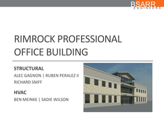
- 1. RIMROCK PROFESSIONAL OFFICE BUILDING BSARR ENGINEERS STRUCTURAL ALEC GAGNON | RUBEN PERALEZ II RICHARD SNIFF HVAC BEN MEINKE | SADIE WILSON
- 3. AUSTIN, TX
- 5. 18,540 TOTAL SQUARE FEET
- 6. 4,500 SQUARE FOOT SURGICAL CENTER
- 8. DESIGN CHALLENGES BSARR ENGINEERS MULTI-STORY ATRIUM GABLE ROOF ATRIUM BALCONY CANTILEVERS GLASS FACADE NARROW PLENUM
- 9. DESIGN CHALLENGES BSARR ENGINEERS LACK OF ARCHITECT PROVIDED CHASES OR FAN ROOMS COMPLEX CODE-REGULATED SURGICAL CENTER ON LOWER LEVEL LEVEL 1 LEVEL 2
- 10. STRUCTURAL DESIGN INTRODUCTION BSARR ENGINEERS
- 11. STRUCTURAL | DESIGN CRITERIA BSARR ENGINEERS Cost Material expense Construction expense Lateral Stability Flexibility Column layouts Durability Constructability Degree of skill Degree of detail
- 12. STRUCTURAL | SYSTEM CONSIDERATIONS BSARR ENGINEERS Reinforced concrete Two-way slab Beams and columns Precast concrete Masonry Masonry exterior walls Reinforced concrete interior Steel Open-web joist
- 13. STRUCTURAL | SYSTEM SELECTION BSARR ENGINEERS Reinforced concrete foundation Typical choice of material Steel superstructure with open-web joists Light, efficient structure Flexible office space Masonry shear walls Durable Easy to construct Solid lateral stability
- 14. STRUCTURAL | SYSTEM SELECTION BSARR ENGINEERS
- 15. STRUCTURAL | CODES AND STANDARDS BSARR ENGINEERS IBC 2009 Live loads Live load reduction provisions Elevator pit live loads ASCE7 Main wind force resisting system procedure Components and cladding procedure AISC 2005 Steel specifications ACI 318-08 Concrete specifications
- 16. STRUCTURAL | LOADING | GROUND FLOOR BSARR ENGINEERS 60 psf 50 psf 50 psf 100 psf 100 psf 100 psf 100 psf 50 psf 50 psf 100 psf 150 psf
- 17. STRUCTURAL | LOADING | SECOND FLOOR BSARR ENGINEERS 50 psf 100 psf 100 psf 50 psf 50 psf
- 18. STRUCTURAL | LOADING | ROOF LEVEL BSARR ENGINEERS 20 psf
- 19. STRUCTURAL | FOUNDATION SYSTEM BSARR ENGINEERS Suspended One-way Slab Piers Grade Beams Interior Exterior Elevator Pit Slab-on-grade Load-bearing walls
- 20. STRUCTURAL | PIERS BSARR ENGINEERS
- 21. STRUCTURAL | PIERS BSARR ENGINEERS
- 22. STRUCTURAL | PIERS BSARR ENGINEERS 22” 26”
- 23. STRUCTURAL | GRADE BEAMS | EXTERIOR BSARR ENGINEERS
- 24. STRUCTURAL | GRADE BEAMS | EXTERIOR BSARR ENGINEERS
- 25. STRUCTURAL | GRADE BEAMS | INTERIOR BSARR ENGINEERS
- 26. STRUCTURAL | GRADE BEAMS | INTERIOR BSARR ENGINEERS
- 27. STRUCTURAL | SLAB SYSTEM BSARR ENGINEERS
- 28. STRUCTURAL | SLAB SYSTEM BSARR ENGINEERS
- 29. STRUCTURAL | ELEVATOR PIT BSARR ENGINEERS
- 30. STRUCTURAL | SUPERSTRUCTURE BSARR ENGINEERS
- 31. STRUCTURAL | COLUMN LAYOUT BSARR ENGINEERS
- 32. STRUCTURAL | LEVEL 2 – DECKING BSARR ENGINEERS
- 33. STRUCTURAL | LEVEL 2 – JOIST SYSTEM BSARR ENGINEERS
- 34. STRUCTURAL | LEVEL 2 – GIRDERS BSARR ENGINEERS
- 35. STRUCTURAL | ROOF LAYOUT BSARR ENGINEERS
- 36. STRUCTURAL | ROOF - DECKING BSARR ENGINEERS
- 37. STRUCTURAL | ROOF – JOIST SYSTEM BSARR ENGINEERS
- 38. STRUCTURAL | ROOF - GIRDERS BSARR ENGINEERS
- 39. STRUCTURAL | LOBBY BALCONY OVERHANG BSARR ENGINEERS
- 40. BSARR ENGINEERS STRUCTURAL | CANTILEVER
- 41. STRUCTURAL | CANTILEVER BSARR ENGINEERS
- 42. STRUCTURAL | GABLE ROOF BSARR ENGINEERS
- 43. STRUCTURAL | GABLE ROOF BSARR ENGINEERS
- 44. STRUCTURAL | GABLE ROOF BSARR ENGINEERS
- 45. STRUCTURAL | GABLE ROOF BSARR ENGINEERS
- 46. STRUCTURAL | GABLE ROOF SUMMARY BSARR ENGINEERS 6 Panel Howe Trusses L4X3X1/4 members Analytical wind load determination SAP modeling C6X8.2 Purlins Lateral stability 1 ½” metal deck L6X6X1/2 Brace frames CMU core
- 47. STRUCTURAL | MWFRS BSARR ENGINEERS
- 48. STRUCTURAL | DIAPHRAGMS BSARR ENGINEERS
- 49. STRUCTURAL | FIRE CORE BSARR ENGINEERS
- 50. STRUCTURAL | FIRE CORE BSARR ENGINEERS
- 51. STRUCTURAL | MWFRS SUMMARY Roof and second floor diaphragms 1 ½” metal deck 3 ½” concrete deck Masonry core 8” CMU walls #4 bars @ 48” Partially grouted 3 hour fire rating BSARR ENGINEERS
- 52. HVAC DESIGN INTRODUCTION BSARR ENGINEERS
- 53. HVAC | CODES & STANDARDS TEXAS ADMINISTRATIVE CODEFOR AMBULATORY SURGICAL CENTERS NFPA 90A, 101 ASHRAE STANDARDS 62.1, 90.1, FUNDAMENTALS, HVAC APPLICATIONS HANDBOOK BSARR ENGINEERS
- 54. BSARR ENGINEERS HVAC | DESIGN PARAMETERS SUMMER DESIGN CONDITIONS: 99°F DRY BULB 74°F WET BULB WINTER DESIGN CONDITIONS: 28°F DRY BULB CITY OF AUSTIN AMMENDMENTS TO THE 2006 IECC
- 55. HVAC | U-VALUES BSARR ENGINEERS GYPSUM BOARD STUD ASSEMBLY WITH R-15 BATT INSULATION DENS GLASS AIR GAP BRICK FACADE CAST STONE EXTERIOR WALL: 0.087 BTUH/FT2 °F GLAZING: 0.470 BTUH/FT2 °F ROOF: 0.048 BTUH/FT2 °F
- 56. HVAC | LEVEL 1 ZONING LAYOUT BSARR ENGINEERS
- 57. HVAC | LEVEL 1 NORTHWEST ZONES BSARR ENGINEERS NORTHWEST ZONES | HP-1 6 TON UNIT
- 58. HVAC | LEVEL 1 SOUTHWEST ZONES BSARR ENGINEERS SOUTHWEST ZONES | HP-3 5 TON UNIT
- 59. HVAC | LEVEL 1 EAST ZONES BSARR ENGINEERS EAST ZONES | HP-4 20 TON UNIT
- 60. HVAC | LEVEL 2 ZONING LAYOUT BSARR ENGINEERS
- 61. HVAC | LEVEL 2 SOUTH ZONES BSARR ENGINEERS SOUTH ZONES | HP-5 7 ½ TON UNIT
- 62. HVAC | LEVEL 2 NORTH ZONE BSARR ENGINEERS NORTH ZONE | HP-2 20 TON UNIT
- 63. HVAC | MECHANICAL EQUIPMENT BSARR ENGINEERS ROOF-TOP HEAT PUMPS BELT DRIVE ADJUSTABLE SPEEDS AIR COOLED CONDENSER LOW INITIAL COST ELECTRIC HEATING COIL SUPPLEMENTS HEAT PUMP FOR EXTREME COLD DAYS
- 64. HVAC | MECHANICAL EQUIPMENT BSARR ENGINEERS TERMINAL UNITS & STEAM HUMIDIFIER VARIABLE AIR VOLUME ELECTRIC REHEAT COIL CONSTANT AIR VOLUME ELECTRIC REHEAT COIL MORE PRECISE HUMIDITY CONTROL IN-DUCT STEAM HUMIDIFIER ADDITIONAL HUMIDITY CONTROL
- 65. HVAC | MECHANICAL EQUIPMENT LAYOUT BSARR ENGINEERS
- 66. HVAC | EXHAUST DUCT LAYOUT BSARR ENGINEERS
- 67. HVAC | SUPPLY DUCT LAYOUT BSARR ENGINEERS
- 68. HVAC | RETURN DUCT LAYOUT BSARR ENGINEERS
- 69. HVAC | COMPLETE DUCT LAYOUT BSARR ENGINEERS
- 70. HVAC | LEVEL 1 NW ZONE BSARR ENGINEERS
- 71. HVAC | LEVEL 1 NW ZONE BSARR ENGINEERS LEVEL 2 PATH TO ROOFTOP UNIT
- 72. HVAC | LEVEL 1 NW ZONE COORDINATION BSARR ENGINEERS
- 73. HVAC | LEVEL 1 SW ZONE BSARR ENGINEERS
- 74. HVAC | LEVEL 1 SW ZONE BSARR ENGINEERS LEVEL 2 PATH TO ROOFTOP UNIT
- 75. HVAC | LEVEL 1 EAST ZONE BSARR ENGINEERS
- 76. HVAC | LEVEL 1 EAST ZONE BSARR ENGINEERS LEVEL 2 PATH TO ROOFTOP UNIT
- 77. HVAC | LEVEL 2 NORTH ZONE BSARR ENGINEERS
- 78. HVAC | LEVEL 2 SOUTH ZONE BSARR ENGINEERS
- 79. HVAC | LEVEL 2 SOUTH ZONE BSARR ENGINEERS
Notes de l'éditeur
- Loads from IBC:Orange: office space, 60 psfBlue:
- Might want to highlight where the 26” piers areAnd where the 22” piers are
- Place a hatch on the two way slabor something to “void” it
- Goal to minimize interior columns and intrusion into rentable space, as well as keep the floor space as flexible as possible for future usesExterior Col:HSS columns used to reduce exposure outside of wallsHSS Sq Columns hidden in exterior wall systemplaced between window openingsLoad bearing shear wall:walls used to frame fire stair. provides required fire break and requires no fire-proofing, like other steel structural members.Masonry workers will be on site for brick veneer work Interior Col:Not obtrusive in rentable spaceHidden in permanent partition wallsCoordination with architect Relocation of doorsOne col had to be offset form gridline to be hidden in wall
- Structural Components:2” LW Concrete on 2 ½” Metal Decking, 22 Gauge, 6 x 6 – W1.4 x W1.4 Welded Wire FabricDeck spans alternate to accommodate for shorter joist spanning
- Open Web Steel Joists:14K6, 16K6No diagonal bridging needed between joists for lateral stabilityDesigned for service requirements of span/240 under unfactored LLConnection:Joists-to-beam, fillet welds to anchor joist to WF beamsJoist-to-CMU, rest on steel bearing PL, fillet welds anchor to PL, embedded in bond beam
- WF BEAMS:W8X10,W12X26, W14X68, W16X100Ranging from 8”-16”Designed for service requirements of Interior: span/360 under unfactored LLExterior: span/240 under unfactored LL (sensistive partitions)Connection:Beam-to-beam: bolted to filet welded anglesBeam-to-CMU: steel beam anchored to bearing PL embedded into mortar, similar to open web JSTBeam-to-COL: WF beam bolted into shear tabs welded to HSS Col
- Structural Components:1 ½” Metal Decking, 18 GaugeRigid insulation on top of deckingActs as a floor diaphragm, which Richard will talk to us about later
- Open Web Steel Joists:8K10, 14K6, 16K6No diagonal bridging needed between joists for lateral stabilityJoist over fire stair supporting deckingBottom chord extensions needed to resist uplift from lateral forcesSame design requirementsConnection: Similar to second floorJoists-to-beam, fillet welds to anchor joist to WF beamsJoist-to-CMU, rest on steel bearing PL, fillet welds anchor to PL, embedded in bond beam
- WF BEAMS:W8X10,W12X26, W14X68Ranging from 8”-14”Same design requirementsConnection:Beam-to-beam: bolted to filet welded anglesBeam-to-CMU: steel beam anchored to bearing PL embedded into mortar, similar to open web JSTBeam-to-COL: WF beam bolted into shear tabs welded to HSS Col
- Structural Components:2” LW Concrete on 2 ½” Metal Decking, 22 Gauge, 6 x 6 – W1.4 x W1.4 Welded Wire FabricDeck spans alternate to accommodate for shorter joist spanning
- Cantilevered to 9’ from girder supportFramed using a W8X35Full moment connection at girder connection, with backspan of 2’Top flange weldSplice plate bolted to top flangesBeam web bolted to welded shear tab on girder webWelded plate bolted to bottom flange of beamW6X25 bolted to cantilever web for lateral torsional stability, Lb=8’
- Cantilevered to 9’ from girder supportFramed using a W8X35Full moment connection at girder connection, with backspan of 2’Top flange weldSplice plate bolted to top flangesBeam web bolted to welded shear tab on girder webWelded plate bolted to bottom flange of beamW6X25 bolted to cantilever web for lateral torsional stability, Lb=8’
- Adjusting speed as a means of controlling a processThe following are process control benefits that might be provided by an adjustable speed drive:Smoother operationAcceleration controlDifferent operating speed for each process recipeCompensate for changing process variablesAllow slow operation for setup purposesAdjust the rate of productionAllow accurate positioningControl torque or tension
- Adjusting speed as a means of controlling a processThe following are process control benefits that might be provided by an adjustable speed drive:Smoother operationAcceleration controlDifferent operating speed for each process recipeCompensate for changing process variablesAllow slow operation for setup purposesAdjust the rate of productionAllow accurate positioningControl torque or tension