Power transmission _distribution_line_trainer_tl_04_26
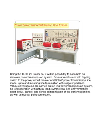
1. Using the TL 04 26 trainer set it will be possibility to assemble an
absolute power transmission system. From a transformer with tapping
switch to the power circuit breaker and 380kV power transmission line
model up to and including line termination with surge impedance.
Various investigation are carried out on this power transmission system,
no load operation with natural load, symmetrical and unsymmetrical
short circuit, parallel and series compensation of the transmission line
as well as neutral-point connection.
2. THREE PHASE TRANSFORMER TL 380 KV 04 26 01 01
Transformer for feeding the transmission line model 380 kV. Scale factor
1:1000 for secondary current and voltage.
Nominal Power : 800 VA
Primary : 3 x 400 V winding with tapping at 230 V, can be switched to star
or delta connection
Delta stabilizing winding can be connected.
Secondary : 3 x 380 V winding with tap-pings at +5%, -5%,
-10%, -15% in star connection, various star Point
connections possible
- Dimension : 420 (W) x 290.70 (H) x 170.80 (D) mm
- Weight : 30 kg
- Unit Type : Panel H3
TRANSMISSION LINE MODEL 380 kV 04 26 01 02
Three-phase model of a 380 kV overhead transmission line For measuring
steadystate operating conditions (no-load, macthing, short-circuit) with the
following specifications : Quad bundle 4 x 240/40, with surge impedance
240W and natural load 600 MW, length 360 km. During symmetrical
operation tappings enable the carrying out of investigations at lengths of
144 km resp. 216 km. Earth return line Re=11W, LE=250 mH for
unsymmetrical load at 360 km line length. Scale factor : 1/1000 for current
and voltage.
Length : 360 km 216 km 144 km
Resistance : 13 Ohm 8 Ohm 5 Ohm
Inductance : 290 mH 174 mH 116 mH
Oper.
Capacity : 5 µF 3 µF 2 µF
- Dimension : 420 (W) x 290.70 (H) x 170.80 (D) mm
- Weight : 23 kg
- Unit Type : Panel H3
TRANSMISSION LINE CAPACITOR TL 380 kV 04 26 01 03
3-phase in star connection , 2.5 µF each, corresponds to 50 % of the
operating capacitance of transmission line model 380 kV
- Dimension : 110 (W) x 290.70 (H) x 130.50 (D) mm
- Weight : 1 kg
- Unit Type : Panel H1
3. POWER CIRCUIT BREAKER MODULE 04 26 01 04
3-phase ON-OFF switch with auxiliary contact (NC) for transmission
line model 380 kV. Can be controlled manually using ON/OFF
pushbutton or externally via switching contact, 4-mm sockets.
Control input for external switch-off command (tripping on faults).
Contact load capacity : 400 V AC , 3 A
Mains connection : 115/230 V, 50 Hz with mains connecting cable and
earthing-pinplug
- Dimension : 110 (W) x 290.70 (H) x 130.50 (D) mm
- Weight : 1.5 kg
- Unit Type : Panel H1
EARTH FAULT COMPENSATION 04 26 01 05
Inductance with 20 tappings for earth fault compensation in the 380 kV
transmission line model (Petersen coil).
Inductance L : 0.005....2 H
Rated voltage : 220 V , 50 Hz
Rated current : 0.5 A
- Dimension : 210 (W) x 290.70 (H) x 130.50 (D) mm
- Weight : 5 kg
- Unit Type : Panel H2
EXCITATION VOLTAGE CONTROLLER 04 26 01 06
DC power supply unit suitable to supply 0-220Vdc, 0-2A adjustable
for excitation voltage in synchronous as generator operation
- Dimension : 210 (W) x 290.70 (H) x 130.50 (D) mm
- Weight : 4 kg
- Unit Type : Panel H2
4. Resistive Load 04 26 02 01
Compose of three resistances with possibility to connect in star/delta or
parallel, controlled by three switches with 7 steps variable per phase
Max Power : 1200 watt
Voltage : 380/220 Volt (Star/Delta)
- Dimension : 440 (W) x 180 (H) x 270 (D) mm
- Weight : 10 kg
- Unit Type : Top Table model
Inductive Load 04 26 02 02
Compose of three inductances with possibility to connect in star/delta or
parallel, controlled by three switches with 7 steps variable per phase
Max Power : 900 VAR
Voltage : 380/220 Volt (Star/Delta)
- Dimension : 440 (W) x 180 (H) x 270 (D) mm
- Weight : 20 kg
- Unit Type : Top Table model
Capacitive Load 04 26 02 03
Compose of three capacitances with possibility to connect in star/delta or
parallel, controlled by three switches with 7 steps variable per phase
Max Power : 900 VAR
Voltage : 380/220 Volt (Star/Delta)
- Dimension : 440 (W) x 180 (H) x 270 (D) mm
- Weight : 5 kg
- Unit Type : Top Table model
5. Three-Phase Synchronous Machine 07 21 03 01
Synchronous machine with three phase winding both stator and rotor for
operation either as motor or as generator
Nominal Power : 1000 VA
Nominal Voltage : 220 / 380 V (Delta/Star)
Nominal Current : 2.6 / 1.3 A (Delta/Star)
Nominal Speed : 3000 rpm.
Excitation : 200V/ 0.59 A
Frequency : 50 Hz
- Dimension : 350 (W) x 270.30 (H) x 260 (D) mm
- Weight : 19 kg
Squirrel Cage Three-Phase Motor 07 21 02 01
Three Phase winding induction motor with squirrel cage rotor.
Nominal Power : 1500 W
Nominal Voltage : 220 / 380 V (Delta/Star)
Nominal Speed : 3000 rpm.
Frequency : 50 Hz
- Dimension : 350 (W) x 270.30 (H) x 260 (D) mm
- Weight : 14 kg
6. Three Phase Power Supply 04 26 03 01
The unit has been designed to provide all fixed and variable AC supplies
which necessary in laboratory to perform the experiment required and
work project. The unit is contained in a metal housing with clear front
panel identification and 4 mm safety sockets that make its easy and safe.
Provided with start stop/stop push bottom emergency mushroom head
push bottom switches and protection
Three Phase AC Adjustable Output : 3x0-380V : 6A
Three Phase AC Fixed Output : 220/380V : 10A
Power Requirement : 220/380V, 50Hz
- Dimension : 540.60 (W) x 320 (H) x 360 (D) mm
- Weight : 29 kg
- Unit Type :
INVERTER UNIT 04 26 03 02
Three phase asynchronous motor speed control by PWM technique.
The Torque and Speed are able to be constant via the unit to easy control
in testing operation during loads change.
Input Voltage : 380V, 50Hz
Output Voltage : 0-380V
Out Frequency : 1-300Hz
Max Power : 1.5 kW
- Dimension : 420 (W) x 290.70 (H) x 170.80 (D) mm
- Weight : 5 kg
- Unit Type : Panel H 3
7. Connecting Safety Leads set SL-04
The set consists of 50 leads in 3 different coded colors and lengths chosen
to allow the realization of all experiment described in the manual. Leads
are capable of 15A current and terminal are 4 mm. safety plugs.
Panel Frame Rack-02
2 Level Aluminum Rack suitable to be supported A4 Panel equipment
Experimental Table 08 21 02 01
Size : 1500x800x800 (mm)
WxHxD
27/19 Mu.5, Talingchan-Suphanburi Rd., Lahan, Bangbuathong, Nonthaburi 11110, Thailand.
Tel : 66 (0)2983 3737 Fax : 66 (0)2983 3738 http://www.kbmeng.com e-mail : kbmeng@asiaaccess.net.th
8. Power Meter HEWa-b
Electrodynamic Power Meter instruments sever to measure direct and/or
alternating current or voltage. Single Phase and Three Phase
Switchable current ranges : AC/DC 1-5-10-20 A
Switchable voltage ranges : AC/DC 12-24-60-120-240-360-480 V
Three-phase AC : 104-208-416 V
Accuracy : 1.0
Power Factor Meter HFQa-b
Ferro dynamic Power Factor Meter instruments are suitable for measuring
power factor in single - or three-phase networks.
Rated current : AC 1-5A
Rated voltage : AC 150-300-450-600 V
Three-phase : AC 150-300-450 V
Accuracy : 1.5
Voltmeter PDV
Moving Coil Movement instruments sever to measure direct and/or
alternating current or voltage.
Switchable voltage ranges
: DC 15-30-100-300 mV 1-3-10-30-100-300-1000V
: AC 1-3-10-30-100-300-1000V
Accuracy : 1.5 (DC)
Accuracy : 2.5 (AC)
Ammeter PDA
Moving Coil Movement instruments sever to measure direct and/or
alternating current or voltage.
Switchable current ranges
: DC 10-50-250mA-1-5-10A
: AC 10-50-250mA-1-5-10A
Accuracy : 1.0 (DC)
Accuracy : 1.5 (AC)
9. 35 MHz Analog Oscilloscope HM303-6
- Maximum signal fidelity with minimum overshoot
2 Channels with deflection coefficients of 1 mV – 20 V/cm, Low Noise
Amplifiers
- Time Base 0.2 s – 100 ns/cm, with X Magnification to 10 ns/cm
- Triggering from 0 to 50 MHz from 5 mm signal level (100 MHz > 8 mm)
- Analog mode provides unexcelled signal presentation at high resolution
and up to 500,000 signal displays/sec.
- Yt,XY and component-test modes
Four Channel Isolating Amplifier 06 21 05 01
4 Channels : can be switches A, AB, ABC, ABCD
Input voltage max. : 4 x 600Vdc/400Vac
Voltage display max. : 4x6Vdc/4Vac
Measuring ranges : 1:1, 1:10, 1:100
Frequency range : 0 … 60 KHz
Input impedance : 10Mohm
Output impedance : 10Kohm
Max read data per ch : 0.5usec
Overscan indication : from 6V
Trigger source : channel A … D
Voltage supply : 220 Vac, 50Hz
Design : Experimental panel system
Dimension in mm : 297 x 210 x 110 ( HxWxD )
Mass : 2.3 kg.
10. Typical Experimental
Three Phase Transformer
- Determination of the winding resistance
- No Load experimental :
Determine the voltage transformation ratio, no-load power factor when fed is carried out from the high voltage
side or from the low voltage side
- Short circuit experimental :
Determine current transformation short circuit voltage and loss (with reduce voltage) short circuit power factor
- Load Measurement :
Inductive, Capacitive, Ohmic determining voltage change and efficiency based on calculation and measurement
value
- Behavior during unsymmetrical load, Influence of the delta compensation winding
- Transformer in economy connection
- Investigations of various switching groups
- Determining the zero-phase-sequence impedance
Transmission Line Model 380 kV
- Behavior of the line at no-load:
Measuring the voltage increases with the line at no-load as well as the charging power for various line lengths
- Behavior of the line during matching:
Measuring and interpreting current and voltage ratios of a line during matching Interpreting the concept of
characteristic impedance, “more than” or “less than” natural load operation, power transmission losses, efficiency
- Interpreting the concept of operation capacitance
- Investigating the operating differences between overhead lines and cables
- Response of the line for various load types:
- Ohmic load
- Mixed ohmic - inductive load
- Mixed ohmic - capacitive load
- Reactive power compensation
- Neutral earthing method
- Fault to earth with isolated neutral earth
- Influence of a Petersen coil
- Unsymmetrical short circuit
- Two-poled short-circuit with / without ground contact
- Single-poled short-circuit
- Determining zero-phase-sequence impedance
11. Generator-fed Power Transmission System with RLC Load
- Measurements on the generator-fed line model under various operating conditions
- Altering the excitation and the influence of this on the voltage
- Influence of the frequency (varying the generator speed)
- Investigating what happens when the generator falls out of synchronization
Parallel and Series Connection of High-voltage Lines
- Measuring the current distribution for two lines connected in parallel and having various lengths
- Investigating the influence of the operating capacitances on voltages and currents
- Measuring the voltages distribution for two lines connected in series and having various lengths
- Determining the relationship between line length and voltage drop